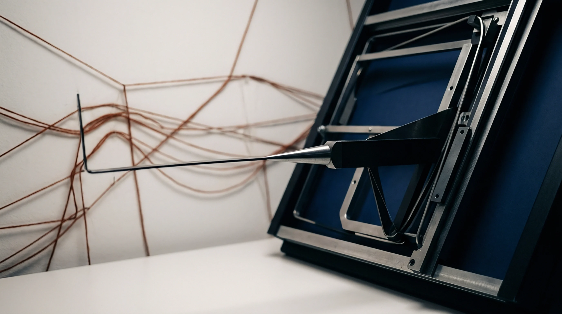
Optical Orientation
Transmission assessment protocols define backlighting geometry as the specific angular relationship between a light source, a translucent textile substrate, and a photoelectric sensor. This physical configuration determines how light rays penetrate fabric voids to reach an internal detector. Precision in this alignment prevents erroneous data acquisition caused by scattered light interference or lens flare.
Standardized calibration of these angles remains necessary for consistent opacity and uniformity testing across diverse fabric weights.
Apparatus Alignment
Verification of equipment performance relies on the exact replication of the defined geometry during each measurement cycle. Any deviation in the distance between the lamp housing and the specimen changes the intensity of the recorded signal. Mechanical stops or fixed mounts restrict movement to keep the light path perpendicular to the sample plane.
High-density fabrics require narrower aperture settings within this geometry to avoid diffraction errors that occur when photons bypass the structure instead of passing through the gaps.
Measurement Sensitivity
Data output from the sensor shows how the spatial arrangement impacts the final transmittance reading for a given sample. Small shifts in the source angle produce disproportionate changes in readings for textured or brushed materials. Laboratories mitigate these discrepancies by enforcing rigid protocols that dictate the source distance and the detector receptive angle.
Controlling these variables ensures that material characteristics like porosity or dye density drive the numerical outcome rather than the setup itself.
Testing Boundary
Technical limitations apply when the chosen geometry interacts with reflective fibers or specialized finishes. Highly conductive or metallic filaments occasionally trigger false signals if the sensor remains too close to the reflective surface within the light path. Testing parameters must exclude setups where the source output exceeds the linear dynamic range of the detector or where ambient light penetrates the measurement enclosure.
Optimal calibration of these mechanical paths maintains the validity of physical properties reported for opaque or semi-opaque textiles.