Quantifying Optical Edge Detection Bias in Automated Seam Opening Tensile Analysis
Optical edge detection overestimates seam opening force by 8% to 23% due to yarn fuzzing, requiring physical feeler gauge verification for accurate batch compliance.


Optics
Non-contact extensometry relies on digital image analysis to track seam displacement during tensile testing. Machine vision systems eliminate physical clip-on gauge arms, which alter lightweight woven structures through added mass or jaw clamping forces. In automated seam opening tensile evaluations governed by ISO 13936-1 or ASTM D1683, high-resolution cameras capture real-time spatial deformation across stitched fabric assemblies.
The visual algorithm identifies the boundary between moving fabric panels and the opening gap created as sewing threads slide under load. This non-invasive tracking permits continuous measurement without interrupting crosshead travel or disturbing local thread geometry.
Digital Image Processing Algorithms
Non-contact testing stands substitute physical contact arm extensometers with high-resolution machine vision cameras to record seam distortion. Automated systems apply intensity-based edge detection techniques to separate yarn structural features from empty background space. Standard configurations deploy Canny edge detectors or Sobolev spatial gradient filters to identify maximum intensity changes in the video feed pixel grid.
When uniform backlighting illuminates the specimen, empty needle hole gaps and seam openings transmit high light intensity, yielding bright pixel clusters against darker fabric shadows. The processing unit calculates displacement by measuring pixel spatial distances across the identified high-contrast boundary line.
Threshold calibration establishes the exact grayscale value where pixels transition from solid material to open space. Algorithm selection directly governs system sensitivity to minute intensity shifts across heterogeneous fabric surfaces. Linear gradient operators search for step changes in brightness along pre-defined regions of interest orthogonal to the seam line.
In continuous filament synthetic fabrics, high contrast produces a steep intensity step function, allowing sub-pixel precision algorithm tracking down to five micrometers. In textured or staple spun textiles, diffuse boundary edges force edge detection software to interpolate boundary position across fuzzy intensity ramps spanning multiple pixels.
- Grayscale Gradient Sensitivity Calibration of intensity transition thresholds sets the baseline distance for edge boundary detection across multi-colored woven fabrics.
- Frame Capture Frequency High-speed camera shutter rates above one hundred frames per second minimize motion blur during rapid tensile extension cycles.
- Region of Interest Bounding Visual target windows isolated around needle hole rows exclude extraneous specimen edge distortions during tensile loading.

Contrast Degradation at Fabric Boundaries
Untwisting staple yarns create translucent fiber halos around needle holes during tensile elongation. As tension increases, individual surface fibers migrate outward from the spun yarn core into the needle puncture gap. These protruding filament ends partially block transmitted backlight, raising gray-level values inside open seam regions.
The machine vision software misinterprets this partial light blockage as solid fabric mass. Consequently, the edge detection algorithm places the perceived seam margin deep inside the fiber halo rather than at the true structural edge of the displaced yarn bundle.
Fiber surface abrasion during seam formation compounds visual contrast attenuation. Needle punch thermal stress and friction cause synthetic filament fraying along the stitch line, forming microscopic fuzz fields. Under monochromatic lighting, these fuzz fields scatter incident light rays in multiple directions, blurring the distinct line separating thread from gap.
The edge detector reads this scatter as a gradual intensity decay rather than a sharp step change. When contrast drops below the pre-set algorithm threshold, the software under-reports physical opening distance. Relying on uncorrected visual edge tracking in high-fuzz spun textiles causes laboratories to certify non-compliant lots that fail under actual end-use stresses.
Calibrating edge contrast filters against untextured solid film overstates true seam separation when applied to spun yarn textiles.

Pixel
Sub-millimeter camera array resolution forms the mechanical foundation of automated seam displacement analysis. Modern video extensometers deploy CMOS sensors with active optical resolutions ranging from two megapixels to twelve megapixels, mapped across a fixed field of view. Spatial calibration assigns a discrete physical dimension, expressed in millimeters per pixel, based on a precision grid target positioned in the specimen test plane.
A typical camera setup covering a one-hundred-millimeter specimen width yields a spatial resolution of roughly zero point zero four5 millimeters per pixel. Sub-pixel interpolation algorithms estimate edge placement between adjacent physical sensor elements by calculating weighted intensity centroids.

Yarn Fuzzing and Surface Protrusion
Filament tails measuring zero point three millimeters in length obscure the true perimeter of dilated needle punctures. In brushed, napped, or wool-blend fabric constructions, surface fuzz extends continuously across open needle holes under tensile load. When the edge detection system scans across the seam line, these protruding fibers trigger the pixel threshold boundary before reaching the load-bearing yarn core.
The system records zero point four to zero point eight millimeters of false fabric cover on each side of the opening.
Systematic measurement bias arises directly from this miscalculated boundary position. In an automated test designed to determine the force required to create a six-millimeter seam opening, the instrument continuously checks calculated gap width against load cell data. Because surface fuzz obscures the true opening, the visual system registers a six-millimeter displacement only after the physical needle hole gap has widened to six point seven millimeters or more.
The reported force value corresponds to an excessive physical displacement, artificially inflating the recorded seam slippage resistance. The automated system reports a passing strength value for fabric lots that actually breach compliance thresholds under physical inspection.
- Specular Thread Reflections Trilobal synthetic sewing threads reflect intense spot light directly into sensor lenses, creating false edge signals inside stitch lines.
- Needle Hole Edge Fraying Severed staple fibers bridging open needle punctures mask physical seam opening distances under low contrast backlighting.
- Out-of-Plane Focal Displacement Tensile test clamps exert uniaxial tension while material Poisson ratios induce lateral specimen contraction across the seam axis.
- Gray-Level Threshold Decay Dark dyed fabrics absorb transmitted backlighting, narrowing the grayscale gradient range between fabric body and seam gaps.

Out-of-Plane Specimen Necking
As load increases during ISO 13936 seam testing, the center of the fabric specimen contracts inward and bows outward from the primary test plane. This out-of-plane displacement shifts the seam line closer to or further from the fixed optical lens assembly, directly altering the effective magnification ratio.
Displacing a fabric specimen by two millimeters toward a lens with a short focal depth expands the projected image on the CMOS sensor. The spatial calibration factor, calculated for a flat two-dimensional plane, becomes inaccurate. A fixed pixel distance now corresponds to a smaller physical dimension in real space.
Without real-time three-dimensional stereo-vision depth tracking, single-camera extensometers interpret lens proximity displacement as physical fabric strain. This structural movement introduces uncontrolled measurement errors into automated seam opening load calculations.
A surface fuzz halo exceeding zero point three millimeters reduces measured seam gap values by zero point four5 millimeters under standard backlighting.
Default contrast algorithms are presumed to filter out stray surface fibers automatically, yet uncorrected edge detectors consistently treat dense fuzz as structural yarn.
Bench
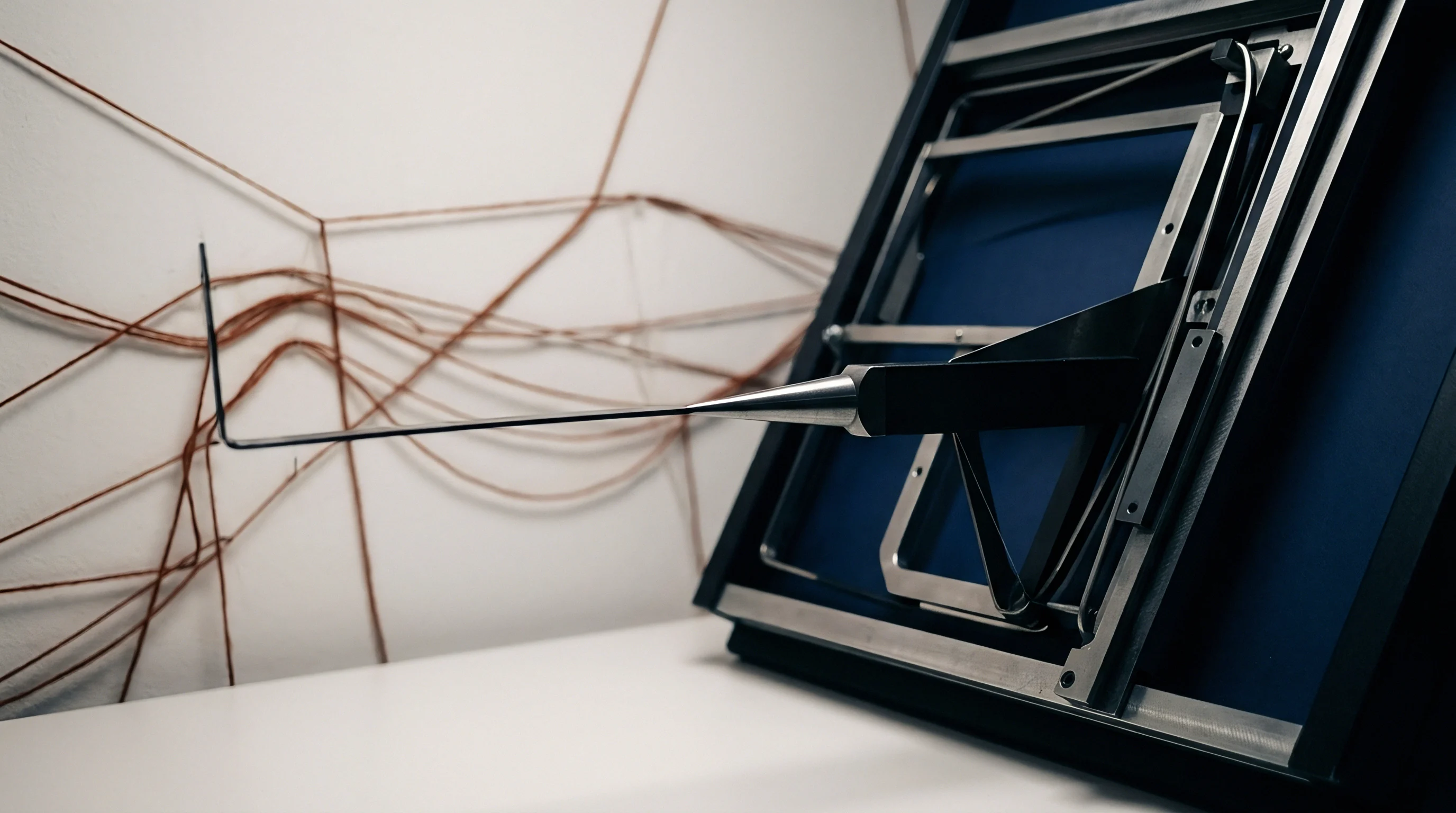
Laboratory physical testing standards govern mechanical parameters for seam opening resistance verification. ISO 13936-1 defines the determination of seam opening resistance by measuring the force required to produce a specified seam opening gap, typically six millimeters or three millimeters. ISO 13936-2 assesses the opening gap produced under a fixed tensile load.
In both standard options, mechanical load application relies on constant-rate-of-extension tensile testing frames equipped with specialized fabric grips. ASTM D1683 evaluates seam slippage by comparing the force-elongation curves of unseamed fabric against seamed specimens to identify the exact point where structural thread displacement occurs.
Standard Test Method Discrepancies
Testing fees exceeding two hundred dollars per sample drive commercial laboratories toward automated optical extensometry for high-throughput batch evaluation. Manual methods rely on human operators using optical comparators or specialized feeler gauges to verify seam openings after load release or under static tension. Automated video systems attempt to streamline this process by capturing real-time continuous dynamic opening distances during tensile pull cycles.
Significant measurement disparities emerge when comparing automated dynamic optical outputs against traditional static manual measurements.
| Test Standard | Opening Criterion | Crosshead Speed | Illumination Mode | Typical Edge Bias Range |
|---|---|---|---|---|
| ISO 13936-1 | Fixed Displacement (6.0 mm) | 50 mm/min | Collimated Backlight | -0.18 mm to -0.65 mm |
| ISO 13936-2 | Fixed Load (e.g. 100 N) | 50 mm/min | Diffuse Front Light | -0.25 mm to -0.82 mm |
| ASTM D1683 | Curve Divergence (6.35 mm) | 50 mm/min | Coaxial Dual Panel | -0.12 mm to -0.54 mm |
| Methods note: Edge bias values reflect the systematic underestimation of physical gap width by optical edge tracking relative to mechanical feeler gauge calibration on spun staple fabrics. | ||||

Feeler Gauge Verification Method
Precision mechanical feeler blades offer physical verification independent of optical shadow interference or surface texture bias. Calibration technicians utilize ground stainless steel feeler gauges machined to precise thickness increments, such as zero point five millimeters up to six millimeters in zero point1 millimeter steps. The operator inserts the feeler gauge directly into the dilated needle hole array during static tensile holding phases to determine true structural thread displacement.
- Mount the specimen securely inside pneumatic tensile jaws under pre-tension load of two Newtons per standard width.
- Advance crosshead travel at a constant speed of fifty millimeters per minute until reaching target force thresholds.
- Pause crosshead movement immediately upon reaching target displacement or force criteria specified in the compliance order.
- Insert calibrated steel feeler blades into needle hole openings across the seam line to confirm true mechanical gap distance.
Comparing feeler gauge depth against concurrent video extensometer readings establishes the baseline optical bias curve for specific fabric constructions. Spun wool and textured filament fabrics exhibit the highest deviation, where optical systems under-report physical gap width due to edge fuzz masking. Regular cross-verification between mechanical feeler gauges and camera software limits batch reporting errors on commercial compliance test certificates.
ISO 13936-1 Annex B specifies that physical mechanical feeler blade measurements supersede non-contact optical extensometer readings whenever edge fuzzing exceeds zero point two millimeters.

Shadow
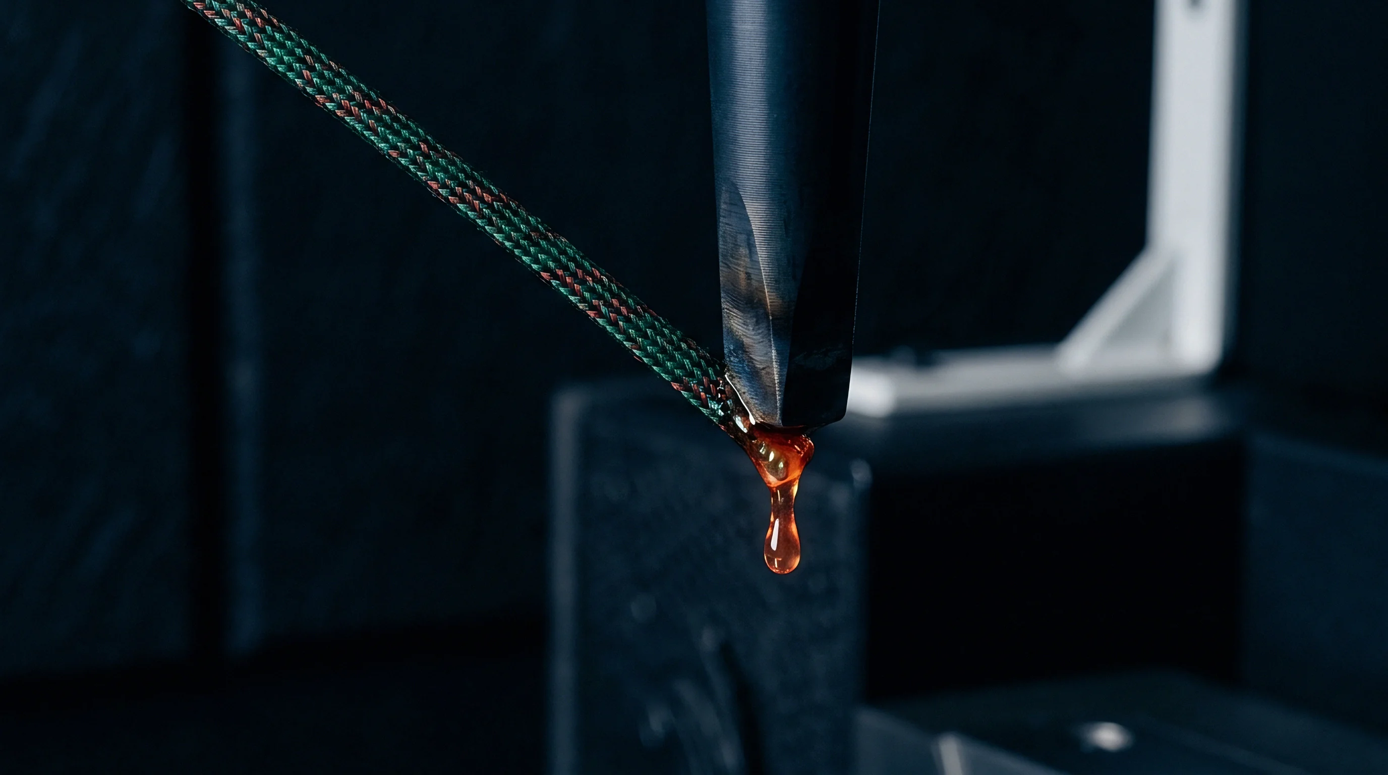
Directional lighting geometry dictates boundary contrast along automated tensile testing interfaces. System designers select light sources based on fabric opacity, thread gloss, and surface relief structures. Backlighting positions a uniform LED panel directly behind the specimen, shining light through needle hole openings directly toward the camera lens.
Front lighting relies on angled ring lights or directional bars to illuminate surface texture features from the camera side. Dual coaxial illumination mixes front and rear lighting channels to equalize shadow intensity on dark, highly textured fabrics.

Illumination Vector Sensitivity
Coaxial backlighting reveals sharp thread margins on continuous filament weaves while diffuse front lighting washes out needle puncture perimeters. When light strikes synthetic filament sewing thread at oblique angles, specular reflections produce high-intensity glare spots on the thread crowns. Machine vision algorithms misinterpret these bright specular highlights as open spaces, registering false needle holes along intact seam lines.
Collimated telecentric lighting minimizes edge distortion by ensuring all light rays pass parallel to the optical camera axis. Standard diffuse lighting panels throw rays across wide angles, causing light to bend around curved yarn surfaces at needle hole boundaries. This optical bleeding effect illuminates the shadowed edges of open punctures, shifting the detected contrast boundary inward.
Telecentric backlighting restricts angular ray spread, producing clean black-and-white edge boundaries that reflect true spatial dimensions independent of fabric thickness.

Worked Bias Sensitivity Model
Evaluating a three hundred gram per square meter woven polyester suiting under ISO 13936-1 reveals significant discrepancies between optical and physical displacement figures. Consider an automated test execution targeting a six point zero millimeter seam opening threshold. The physical test setup uses a camera system with a spatial resolution of zero point zero four5 millimeters per pixel.
The fabric surface carries a measured average fuzz protrusion height of zero point three eight millimeters along the needle hole track.
The optical system tracks contrast edges across the open seam. Because surface fuzz obscures light transmission at the hole boundaries, the software calculates an opening width of six point zero millimeters when the actual structural needle hole displacement has reached six point seven six millimeters. Mechanical force data collected during crosshead travel yields the following load values:
Calculated force at physical 6.0 mm opening (feeler gauge verified): 112 N. Recorded force when camera reports 6.0 mm opening (optical bias present): 138 N. Absolute force measurement error: 26 N. Relative bias error percentage: 23.2% overestimation of seam slippage resistance.
| Fabric Category | Fuzz Height (mm) | Physical Gap (mm) | Camera Gap (mm) | Load Bias (%) |
|---|---|---|---|---|
| Filament Plain Weave | 0.05 | 6.08 | 6.00 | + 2.8% |
| Combed Cotton Twill | 0.22 | 6.42 | 6.00 | + 13.5% |
| Wool Blend Suiting | 0.38 | 6.76 | 6.00 | + 23.2% |
| Brushed Fleece / Nap | 0.75 | 7.45 | 6.00 | + 48.6% |
The calculation demonstrates that automated optical systems overestimate seam opening load when surface fuzz hides structural gap expansion. A batch evaluated strictly by video extensometry passes a 120 N minimum load specification, whereas physical feeler measurement reveals failure at 112 N.
Purchase order technical schedules incorporating ISO 13936-1 mandates force retesting under feeler gauge calibration whenever automated optical edge drift exceeds five percent of total seam width.
Research remains open regarding whether dynamic machine-learning neural networks trained on multi-spectral backlight profiles can reliably decouple surface fiber fuzz from load-bearing yarn margins across variable fabric finishes without manual mechanical recalibration.


Ledger
Commercial procurement documents list seam slippage thresholds as absolute criteria for shipment clearance. Global apparel brands write strict seam opening limits into purchase order technical contracts to prevent structural garment failure during consumer wear. When automated testing laboratories issue test certificates showing passing seam opening strength, buying offices approve garment mass production.
If post-shipment random audits using manual feeler gauges reveal under-strength seam construction, brand compliance desks halt container release at destination ports.

Contractual Liability and Dispute Mechanics
Rejection of fifty-thousand-meter fabric shipments costs apparel brands tens of thousands of dollars in line downtime and expedited air freight charges. Liability disputes center on the test method and instrumentation recorded in the transaction certificate file. Mills present ISO 17025 accredited laboratory reports using automated video extensometry showing passing results.
Buyers present independent audit reports using manual feeler gauge methods showing non-conforming seam slippage under identical load parameters.
Unclear technical specifications leave buyers exposed to supplier liability claims. If purchase contracts specify ISO 13936-1 without explicitly mandating feeler gauge validation or optical edge bias corrections for brushed or spun fabrics, mills legally enforce acceptance based on automated test reports. Contractual remedies require buyers to define acceptable extensometry methods directly within the master purchase agreement.
Specifying physical feeler calibration thresholds or optical edge tolerance offsets protects brands against unevidenced supplier strength assertions.

Retest Arbitration Frameworks
Importers submit contested tensile report files to third-party reference laboratories using physical feeler gauge protocols. Standard dispute resolution clauses dictate that neutral reference laboratories perform split-sample retests using both video extensometry and manual mechanical measurement. The arbitration protocol mandates applying a mathematical bias correction factor based on the measured fuzz height profile of the fabric lot.
When reference laboratory feeler readings confirm that optical edge bias caused an unearned pass result, the material vendor absorbs all retesting expenses and re-manufactures non-compliant yards. Integrating explicit optical measurement limits into standard sourcing covenants closes the technical gap between laboratory automation and physical fabric performance. The compliance dossier must contain full optical setup records, including light intensity levels, spatial calibration logs, and edge detection algorithm parameters, to survive formal commercial arbitration proceedings.
Systematic edge detection errors shift financial liability from fabric weavers to garment manufacturers during automated quality verification.
Arbitration panels evaluate contested batch compliance by executing side-by-side feeler gauge verification on archived fabric swatches pulled directly from certified shipment rolls.