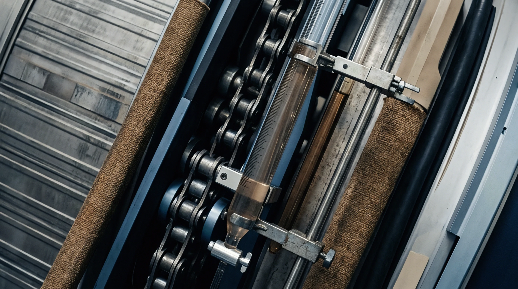
Pressure Differential
Pump hydraulic dynamics define the energy loss occurring between the source liquid reservoir and the impeller inlet. Suction head loss quantifies the resistance encountered by fluid as it travels through pipes, valves, and strainers toward a pump. This measurement identifies the energy expenditure required to move process water through a dyeing machine intake line.
Engineers calculate these values to ensure the fluid maintains enough velocity to prevent cavitation at the pump eye. Precision is necessary during the installation of high-capacity centrifugal pumps feeding textile finishing ranges.
Flow Resistance
Pipe friction and component turbulence determine the magnitude of this energy reduction. Velocity increases the drag against internal pipe walls while bends and fittings create turbulence that dissipates pressure. A long run of small-diameter stainless steel piping generates higher values than a shorter, wider setup.
Gravity assists in reducing this loss when the source tank sits above the pump inlet. Fluid viscosity variations during additive injection cycles change the density of the process stream, which alters the drag force.
Performance Constraint
Cavitation risk increases when the pressure at the impeller inlet falls below the vapor pressure of the handled liquid. Pumps fail to deliver required flow rates if the suction head loss exceeds the net positive suction head available to the system. Excessive restriction at the intake leads to vapor bubbles that implode against metal surfaces.
These collapses damage impeller vanes and degrade pump efficiency over time. Stable operation depends on maintaining a pressure head that accommodates the internal friction of the delivery hardware.
Measurement Protocol
Technicians verify these losses by comparing gauge readings taken at the intake flange against the static pressure of the supply vessel. Verification occurs during the commissioning phase of a textile production line or after replacing significant sections of feed piping. Flow meters confirm if actual resistance aligns with calculated hydraulic models for the specific liquid being processed.
Discrepancies between measured data and design expectations indicate internal fouling or physical obstructions within the intake architecture. Accurate monitoring prevents mechanical wear and ensures consistent chemical delivery to processing machinery.