Modeling Multi-Pass versus Single-Pass Digital Printhead Array Depreciation and Fluid Loss Economics in Sourcing Contracts
Single-pass printhead arrays incur higher capital depreciation and fluid purge waste than multi-pass engines, demanding strict contract coverage caps.
Wear
Piezoelectric elements in modern digital printing arrays experience mechanical shear under high-frequency pulse execution. Lead zirconate titanate ceramic stacks change shape under applied electrical potentials, driving fluid drops through nozzle apertures ten to thirty micrometres wide. Operating at pulse frequencies between fifteen and forty kilohertz, individual nozzle channels execute billions of mechanical flexures a week.
Over time, internal polarization decay, micro-cracking in the ceramic lattice, and mechanical fatigue alter the acoustic performance of the jetting chamber. PZT ceramics degrade under sustained firing stress ~ a physical change that distorts drop ejection velocity and drop mass, directly affecting visual density and color consistency on printed goods.
Drop volume shifts directly alter color yield. A nominal seven-picolitre drop channel that decays to five point eight picolitres reduces total colorant deposition by seventeen percent. On light shades, this reduction causes visible lightness shifts; on heavy blotches, it manifests as pin-holing and inadequate wet-out across woven substrate structures.
Multi-pass scanning arrays and single-pass fixed bars distribute this physical degradation in fundamentally different patterns across their mechanical lifespans.

Actuator Degradation in Piezoelectric Printhead Arrays
Lead zirconate titanate crystal stacks undergo structural alterations at the microscopic level when subjected to continuous electrical drive waveforms. Applying high drive voltages to maintain drop velocity as fluid viscosity fluctuates accelerates polarization loss inside the PZT crystal lattice. As acoustic resonance within the jetting chamber degrades, the drive controller increases pulse amplitude to sustain target drop speeds of six to eight metres per second.
This voltage compensation cycle creates a feedback loop: higher drive voltage generates increased internal heating, which further degrades the piezoelectric element.
Cavitation erosion presents another physical damage mechanism inside the nozzle plate. Fluid retraction after drop detachment draws microscopic air bubbles into the nozzle chamber. Under continuous pulse cycles, these micro-bubbles collapse against internal chamber walls with localized pressure spikes exceeding one hundred megapascals.
Cavitation pits the nickel or silicon nozzle plate material, distorting the interior fluid channel geometry. Distorted orifices deflect drop trajectories away from perpendicular ejection, producing streak artifacts across the substrate path. Meanwhile, polyurethane wiper blades used during maintenance wipes physically abrade external nozzle coatings over repeated cleaning cycles, lowering fluid repelling properties and encouraging ink pooling around the orifice edge.

Frequency Stress Dynamics in Scanning versus Fixed Arrays
Thermal dissipation rates differ markedly between moving scanning carriages and full-width print bars. Multi-pass scanning engines move printhead blocks back and forth across moving cloth widths, intercutting directional strokes with brief deceleration periods at carriage turnarounds. These momentary pauses allow localized heat generated within the PZT stacks to dissipate into the surrounding frame and air currents.
The scanning motion spreads jetting duties across multiple passes over the same area of cloth, masking individual nozzle drop volume variations through interlaced dot placement patterns.
Single-pass architectures mount stationary printhead arrays in fixed bars spanning the full width of the web, typically one point eight to three point two metres wide. Substrates move beneath these bars at continuous speeds ranging from forty to ninety metres per minute. Every nozzle in a single-pass array fires at maximum operational frequency without mechanical pauses.
Heat accumulates rapidly inside dense printhead clusters, raising fluid temperature inside the manifold by three to eight degrees Celsius above ambient room conditions. Temperature spikes lower ink viscosity, causing drop volume growth followed by sudden starvation when internal fluid feed channels cannot replenish high-frequency drop demand.
Piezoelectric array drop volume decays by eight percent after one hundred billion firing cycles at forty kilohertz operation.
Single-pass arrays lack the mechanical spatial averaging inherent in multi-pass scanning. If a single nozzle in a fixed bar suffers voltage decay or partial orifice blockage, it leaves an unprinted line along the entire length of the production run. Single-pass architectures rely on automated drop substitution algorithms, forcing adjacent healthy nozzles to fire extra drop volumes or secondary micro-drops to fill the missing optical coverage.
This localized over-firing accelerates mechanical wear on adjacent actuators, compounding array degradation over extended mill operating schedules.
- PZT Polarization Decay occurs as continuous high-frequency pulse excitation permanently degrades crystal lattice response over seventy billion actuation cycles.
- Orifice Cavitation Pitting alters internal channel acoustics, forcing ejection velocity down from seven point five metres per second to below five metres per second.
- Nozzle Plate Abrasion results from mechanical wiper contact, stripping hydrophobic fluoropolymer coatings and increasing fluid pooling risk around jet orifices.
- Thermal Gradient Drift inside dense single-pass bars increases ink temperature, lowering fluid viscosity and distorting target drop mass during continuous high-speed runs.
- Voltage Compensation Fatigue shortens overall array lifespan as driver chips push higher currents into aging piezoelectric elements to maintain drop ejection speed.
Quantifying mechanical depreciation demands tracking cumulative drop firing counts alongside operational frequency metrics. Multi-pass systems spread mechanical duty cycles across longer time horizons per printed metre, whereas single-pass bars compress years of actuator stress into months of continuous full-width operation.
| Performance Parameter | Multi-Pass Scanning Array | Single-Pass Fixed Bar Array | Impact on Printed Goods |
|---|---|---|---|
| Operational Firing Frequency | 12 kHz to 24 kHz | 30 kHz to 48 kHz | Higher frequencies in single-pass drive thermal accumulation and PZT crystal decay. |
| Array Thermal Gradient Delta | 1.5 to 3.0 degrees C | 4.5 to 9.0 degrees C | Viscosity shifts distort drop mass control across full width on single-pass bars. |
| Nozzle Redundancy Capability | High (Interlaced multi-pass sweeps) | Low (Digital drop compensation only) | Single-pass weak nozzles leave visible warp-wise streak defects instantly. |
| Average Array Lifespan (Fires) | 120 to 180 Billion drops | 60 to 90 Billion drops | Single-pass arrays demand replacement twice as frequently under equivalent volume. |
| Mechanical Turnaround Pause | 0.15 to 0.35 seconds per pass | None (Continuous web travel) | Multi-pass carriage turnaround provides passive thermal dissipation cycles. |
Array degradation rates dictate printhead replacement timelines, governing baseline capital recovery math across long-term sourcing contracts.
Arrays operating at elevated drive voltages without temperature compensation fail long before reaching their theoretical pulse actuation threshold.


Purge
Fluid movement through high-density jetting channels serves the dual functions of ink delivery and orifice clearing. Ink jetting maintenance routines prevent fluid drying within exposed nozzle tips during idle production periods. When digital printing machinery pauses between production rolls or pattern file transfers, volatile solvent or water components evaporate from open orifices.
Idle printheads dry quickly on open bars. Solute concentrations rise at the air-ink interface, forming high-viscosity skin layers or solid binder plugs that block drop ejection upon restart.
Automated maintenance cycles use positive hydraulic pressure pulses, vacuum meniscus pulling, and micro-spitting routines to clear gelled ink from jetting chambers. Ink chemistry governs purge fluid volume. Reactive dye inks, acid colorants, disperse dye systems, and pigment dispersions exhibit distinct fluid loss profiles during maintenance cycles, directly altering the landed cost of printed substrate metreage.
Hydrodynamic Recirculation and Meniscus Control
Negative pressure systems maintain fluid retention at the orifice plate within strict atmospheric differentials. Sub-tank vacuum pumps maintain negative hydrostatic pressure between negative one point two and negative two point five kilopascals at the nozzle orifice. This capillary meniscus prevents ink from weeping under gravity while maintaining fluid readiness for immediate acoustic firing pulses.
In continuous recirculation architectures, ink flows past the back of the jetting chamber at high rates, carrying away entrained micro-bubbles and preventing pigment settling.
Positive pressure purges override negative meniscus controls during automated cleaning routines. Pumps apply positive hydraulic pressure between twenty-five and seventy kilopascals to internal fluid manifolds, forcing three to ten millilitres of ink per printhead through active orifices within two seconds. This high-velocity fluid flow sweeps away debris, gelled binder polymer, and air pockets.
Vacuum capping stations engage nozzle plates immediately after positive flushing, drawing residual ink droplets away from the external orifice surface before silicone or polyurethane blades perform a wiping stroke.
Continuous ink recirculation protects nozzle apertures during extended production pauses while increasing baseline fluid consumption.

Volumetric Waste Metrics across Industrial Chemistries
Reactive dyes and pigmented dispersion systems exhibit distinct maintenance loss profiles. Reactive dye formulations rely on water-soluble colorants that remain stable in aqueous media, allowing soft micro-spitting routines to keep nozzles open during short pauses. Pigment inks contain insoluble organic or inorganic particles bound in resin binders.
When pigment ink sits stagnant in non-recirculating channels, binder agglomeration occurs rapidly. Pigment nozzle maintenance requires higher pressure pulses and more frequent flushing cycles to maintain drop reliability.
Acid inks used on silk and polyamide substrates exhibit sensitivity to atmospheric humidity variations. Under low relative humidity conditions on dyehouse floors, acid ink orifices skin over within thirty seconds of idle time. Single-pass arrays housing upwards of sixty-four individual printheads generate substantial waste ink volumes during routine purge maintenance.
A full-bar positive purge on a six-color single-pass printing machine consumes between two hundred and five hundred millilitres of ink per event. Over a twenty-four-hour operating cycle incorporating roll changes, pattern loading, and periodic maintenance, single-pass fluid loss reaches eighteen to thirty-five litres of virgin ink.
- Pigment Binder Agglomeration blocks internal nozzle filters, requiring high-pressure purge pulses that consume up to forty millilitres per channel daily.
- Reactive Dye Hydrolysis in stagnant fluid lines mandates full system flushes following multi-shift weekend downtimes to restore color yield purity.
- Micro-Spitting Waste Generation consumes continuous fluid volumes as non-printing nozzles fire up to two thousand drops per second into spittoon gutters.
- Sub-Tank Recirculation Thermal Loss shear-degrades heat-sensitive disperse ink dispersants, forcing scheduled fluid dumps to maintain jetting stability.
Plant audits record ink purge losses exceeding twenty-two percent on poorly calibrated single-pass bars. Comparing fluid loss dynamics between scanning engines and stationary arrays highlights stark differences in baseline operating overhead.
Single-pass architectures consume high fluid volumes during cleaning because the entire full-width array must be purged simultaneously, even if only a fraction of nozzles experienced idle drying. Multi-pass scanning engines isolate individual printhead blocks for targeted purge routines, keeping maintenance fluid loss below ten percent of total ink consumption under equivalent production volumes.
Sourcing managers who fail to separate theoretical print coverage from total fluid intake underwrite the financial burden of mill maintenance inefficiencies.

Platen
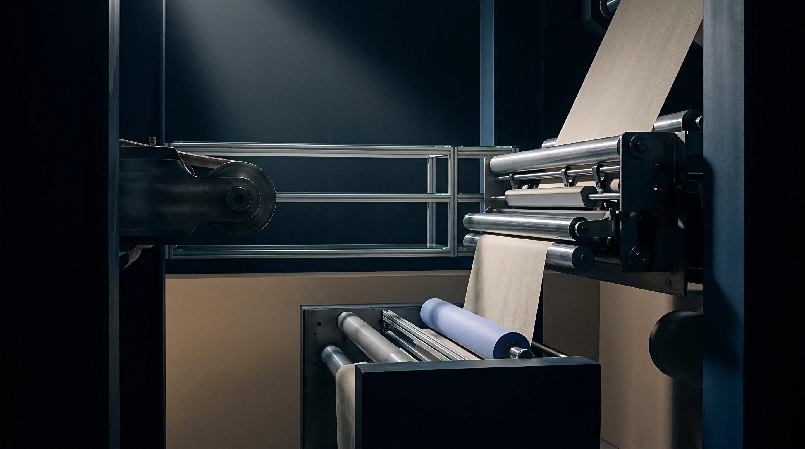
Substrate transport systems dictate the physical registration of microscopic ink droplets delivered across wide widths. Transport mechanism accuracy governs optical clarity, line crispness, and shade uniformity on finished printed goods. Synthetic sticky-belt conveyor systems move textile substrates beneath digital printhead arrays, utilizing water-soluble resin adhesives or permanent thermoplastic coatings to immobilize stretchable knit goods and light woven structures during ink deposition.
Substrate speed, tracking alignment, and mechanical vibration control differ fundamentally between multi-pass scanning platforms and single-pass continuous architectures. Matching array jetting geometry to belt linear velocity defines the physical limits of production speed and machine capital expenditure.
Substrate Velocity Matching and Belt Tracking
Continuous thermoplast conveyor belts demand sub-millimetre mechanical tracking across long runs. In single-pass printing configurations, the fabric web travels beneath stationary color bars at linear speeds exceeding one metre per second. At these speeds, a belt tracking deviation of merely zero point zero five millimetres creates visible diagonal skew and registration errors between consecutive color bars.
Servo-driven encoder systems monitor belt displacement at sub-micron increments, adjusting jetting trigger timing dynamically across the array to maintain dot placement accuracy within ten micrometres.
Belt washing units mounted underneath the machine frame continuously strip lint, unfixed dye residue, and adhesive excess from the conveyor surface. Excessive water application or incomplete rotary squeegee drying alters the surface tension of the sticky belt, causing localized substrate slipping under high linear acceleration. Substrate slippage alters the distance between the printhead nozzle plate and the cloth surface.
Increasing nozzle gap distance from one point five millimetres to two point five millimetres allows air turbulence generated by fast web movement to deflect drop trajectories, blurring fine lines and reducing edge sharpness on micro-patterns.
Where Do Hidden Ink Purge Costs Accumulate?
Non-printing intervals between commercial production lots trigger automatic cleaning sequences. While moving fabric webs pass beneath active bars, color channels fire according to image file coordinates. When production stops for roll replenishment, pattern adjustments, or shade approval checks, single-pass printhead bars remain exposed to room air currents generated by drying units mounted downstream.
Air movement across idle nozzle plates accelerates localized solvent evaporation, forming viscous ink crusts inside nozzle apertures within sixty seconds. To prevent permanent channel clogging during roll changes, machine automation software executes micro-spitting routines, firing thousands of droplets per nozzle per second directly into underlying transport belt gutters or dedicated spittoon receivers. This continuous maintenance jetting consumes significant fluid volumes while generating no billable print output.
Automated recirculation systems do not completely eliminate maintenance fluid loss during idle periods; positive pressure purging remains physically necessary to clear micro-bubbles and dried surface skinning from non-recirculating orifice tips. In actual dyehouse practice, single-pass machines idling between short customer lots dump substantial volumes of prime ink into waste reclamation drums simply to maintain array readiness.
Multi-pass scanning platforms reduce idle drying exposure by moving the printhead carriage into sealed capping stations during roll changes. The physical carriage rests over humidified solvent sponge caps, preventing surface skinning without requiring continuous micro-spitting jetting routines. Consequently, multi-pass configurations consume significantly less maintenance fluid during short-run production environments involving frequent pattern changes.
Printhead array maintenance costs are often framed as fixed baseline overhead tied to factory floor humidity, though machine-level purge routines and fluid dynamics drive much of the variance.


Costing
Financial modeling for digital print production requires allocating capital expenditure alongside fluid loss across projected linear volume. Sourcing contracts that treat digital printing as a simple per-metre conversion fee obscure underlying machinery depreciation curves and fluid wastage penalties. Calculating total landed manufacturing cost demands separating hardware amortization, head array replacement reserves, jetting ink consumption, and maintenance purge waste into distinct financial variables.
Capital costs and fluid mechanics vary dramatically between multi-pass scanning engines and full-width single-pass print lines. A rigorous economic model isolates these variables across different order volume thresholds, identifying the precise break-even points where single-pass speed outweighs its substantially higher fixed asset depreciation and baseline fluid waste overhead.

Capital Amortization per Linear Metre of Printed Goods
Printhead replacement intervals establish the foundational baseline for fixed machinery depreciation. High-speed single-pass digital printing installations represent major capital outlays, often costing between one point five million and three point five million US dollars depending on width, color bar configuration, and belt automation features. A typical eight-color single-pass line utilizes ninety-six industrial piezoelectric printheads mounted across eight stationary color bars.
At an average replacement cost of three thousand two hundred dollars per printhead, replacing a complete array requires an outlay of three hundred and seven thousand two hundred dollars.
Assuming a conservative single-pass array operational lifespan of eighty billion firing cycles per nozzle, a double-shift dyehouse operating at sixty metres per minute exhausts printhead array performance within twelve to eighteen months. Capital depreciation reserves must therefore accumulate between sixteen thousand and twenty-five thousand dollars monthly simply to fund scheduled array replacement. Multi-pass scanning machines carry significantly lower capital expenditure profiles, utilizing twelve to sixteen printheads on a total machine investment of three hundred thousand to five hundred thousand dollars, yielding substantially smaller replacement reserve allocations per operating month.
Fixed costs dominate small volume runs. When amortized across low annual production volumes, single-pass array depreciation drives conversion costs to unsustainable levels. Single pass demands continuous operational scale.
Only high-volume manufacturing environments can absorb fixed head replacement outlays without inflating per-metre conversion charges.
Fluid Allocation Arithmetic in Volume Sourcing
Calculating true ink consumption involves adding maintenance loss directly to theoretical drop laydown figures. Theoretical ink coverage depends on fabric construction, yarn size, pick density, and visual pattern design. A medium coverage reactive print on a one hundred and fifty gram per square metre cotton poplin requires approximately eight point five grams of wet ink deposition per square metre to achieve target color depth and penetration through to the fabric reverse side.
Maintenance fluid loss multipliers must be applied to theoretical ink mass to determine total fluid procurement requirements. Multi-pass scanning platforms run on an average fluid loss factor of seven to eleven percent, reflecting localized purging and low-volume idle spitting routines. Single-pass architectures operate with fluid loss factors between sixteen and twenty-six percent, driven by continuous bar micro-spitting, automatic full-width pressure purges, and roll-transition line clearing.
| Cost Component (USD per 1,000m) | Multi-Pass (50k m/yr Run) | Multi-Pass (500k m/yr Run) | Single-Pass (500k m/yr Run) | Single-Pass (3M m/yr Run) |
|---|---|---|---|---|
| Capital Asset Amortization | $1,200.00 | $120.00 | $720.00 | $120.00 |
| Printhead Replacement Reserve | $160.00 | $150.00 | $614.40 | $307.20 |
| Theoretical Ink Laydown (8.5 g/m²) | $178.50 | $178.50 | $178.50 | $178.50 |
| Maintenance Purge Waste Ink Cost | $16.07 (9%) | $16.07 (9%) | $37.49 (21%) | $37.49 (21%) |
| Direct Power & Water Overhead | $45.00 | $40.00 | $22.00 | $18.00 |
| Total Conversion Cost per 1,000m | $1,599.57 | $504.57 | $1,572.39 | $661.19 |
The financial data illustrates the structural economic threshold between technologies. At five hundred thousand linear metres per year, multi-pass scanning platforms deliver a significantly lower conversion cost than single-pass lines ($504.57 versus $1,572.39 per thousand metres). The high capital cost and elevated printhead replacement reserve of single-pass arrays penalize low-to-medium production volumes.
Single-pass architectures require annual volumes exceeding two point five to three million linear metres to reduce capital depreciation per metre to levels competitive with multi-pass platforms. Single-pass fluid waste overhead remains permanently higher regardless of volume, adding twenty-one dollars and forty-two cents of excess purge loss per thousand metres over multi-pass systems due to systemic array flushing dynamics.
To quantify total financial exposure, consider a worked calculation for a brand sourcing two million linear metres of printed viscose woven cloth over a twelve-month contract period. Theoretical ink coverage averages nine point two grams per square metre using reactive inks priced at twenty-two dollars per kilogram. Multi-pass ink procurement math evaluates as follows:
Theoretical ink mass: 2,000,000 metres x 1.4 metre width x 9.2 g/m² = 25,760 kilograms of ink.
Multi-pass waste factor at 8.5 percent: 25,760 kg x 1.085 = 27,949.6 kilograms total ink required.
Total multi-pass ink spend: 27,949.6 kg x $22.00/kg = $614,891.20 USD.
Single-pass ink procurement math for the identical volume evaluates as follows:
Theoretical ink mass: 25,760 kilograms of ink.
Single-pass waste factor at 22.0 percent: 25,760 kg x 1.220 = 31,427.2 kilograms total ink required.
Total single-pass ink spend: 31,427.2 kg x $22.00/kg = $691,398.40 USD.
The fluid loss differential between printing architectures yields a direct ink cost penalty of seventy-six thousand five hundred and seven dollars and twenty cents on single-pass equipment for the same printed job volume.
Add to this fluid penalty the printhead replacement reserve differential. Over two million metres, a single-pass array consuming nozzle life at thirty kilohertz requires approximately six hundred and fourteen thousand four hundred dollars in head array reserve accruals ($0.3072/m). The multi-pass system accrued three hundred thousand dollars ($0.1500/m) over the same volume.
Total execution cost differential including fluid loss and head reserve penalties reaches three hundred and ninety thousand nine hundred and seven dollars and twenty cents favoring multi-pass machinery, unless single-pass throughput velocity generates equivalent labor and facility overhead savings.
At what exact volume threshold does machine throughput speed offset higher baseline fluid loss and printhead replacement reserves when negotiating long-term converter unit prices?


Clause
Commercial sourcing agreements specify liability parameters for array degradation and fluid loss overruns. When brand sourcing teams negotiate digital printing conversion contracts with commission mills, failure to specify physical operational baselines results in uncontained cost pass-throughs. Mills operating high-speed single-pass machinery frequently seek to blend high capital replacement expenses and elevated ink purge losses into general yardage surcharges, shifting operational risks directly onto the buyer.
Contract clauses must define exact boundaries for acceptable printhead degradation, establishing quantitative thresholds for drop velocity decay, shade variation, line registration, and maintenance waste allowances. Contract terms determine who absorbs fluid waste. Well-drafted supply agreements isolate hardware wear metrics from true ink consumption, establishing verifiable auditing frameworks for bulk production orders.

Drafting Array Depreciation Terms in Supply Contracts
Structuring financial liability for printhead failure requires separating normal drop volume decay from catastrophic mechanical breakdown. Supply contracts should establish a baseline printhead depreciation fee tied directly to verifiable dot actuation counts or logged linear metreage, preventing printers from charging arbitrary array replacement surcharges when printheads fail prematurely due to poor maintenance or improper ink filtration.
Array depreciation clauses must explicitly tie head replacement reserve billing to print quality output measured under standard lighting conditions and international testing standards. If an array experiences nozzle clogging or drop deflection resulting in warp-wise streak defects exceeding ISO 105 color fastness or visual shade variation limits (Delta E greater than one point zero under D65 and TL84 illuminants), the contract must obligate the printer to replace degraded printheads at their own expense without billing the buyer for lost production time or scrap cloth.
Risk Distribution for Ink Maintenance Surcharges
Volumetric ink billing models protect printers from variable pattern coverage while exposing buyers to unmonitored maintenance flushing. When sourcing contracts specify ink pass-through billing where the buyer pays for all ink consumed during production, the converter has zero commercial incentive to minimize purge frequency or optimize micro-spitting routines.
To eliminate this misaligned incentive, sourcing contracts must establish a capped fluid loss baseline. The contract specifies theoretical ink coverage calculated via raster image processor software for each pattern design, adding an agreed maintenance waste allowance (for example, eight percent for multi-pass or fifteen percent for single-pass). Any ink consumption exceeding this total calculated ceiling is absorbed entirely by the printing mill as an operational inefficiency penalty.
Contracts invoking ISO 105 shade tolerances impose full fluid waste liability on the printer when purging routines cause continuous lot variation.
Contractual risk distribution frameworks must also address substrate waste generated during printhead recovery purges. When single-pass arrays undergo automated pressure purges mid-run, several metres of moving fabric web pass beneath the color bars during fluid jetting, resulting in unprintable blotched scrap. Unmonitored purging destroys profit margins.
Supply agreements must explicitly cap allowable substrate scrap rates at one point five percent of total order length, penalizing converters for excessive scrap generation resulting from poorly maintained array manifolds.
A structured sourcing contract clause governing printhead array depreciation and fluid loss reconciliation defines commercial boundaries clearly:
The converter agrees that ink volume billing shall not exceed theoretical design coverage plus a maximum allowable maintenance purge factor of fourteen percent for single-pass production or eight percent for multi-pass production. Theoretical ink coverage shall be calculated using the native raster image processing software prior to production and validated against dry substrate mass gain measured according to ISO 3801 conditioning standards. Any fluid consumption recorded above this combined threshold, including ink consumed during automated pressure purges, nozzle recovery flushing, or idle micro-spitting, shall be borne exclusively by the converter.
Furthermore, printhead replacement reserves billed to the buyer shall be capped at zero point zero eight US dollars per linear metre for multi-pass production and zero point eighteen US dollars per linear metre for single-pass production. In the event that nozzle ejection failure causes visible warp-wise banding or color shade drift exceeding Delta E equal to one point zero under ISO 105-J03 color difference evaluation, the converter shall pause production, replace affected printhead modules at its own expense, and reprint damaged yardage at no additional cost to the buyer.
Including explicit performance language shifts array maintenance discipline back to the dyehouse floor, compelling mill managers to monitor jetting voltage and meniscus pressures continuously.

Settlement
Post-production auditing confirms financial alignment between contracted unit rates and actual mill floor execution. Reconciling digital printing invoices requires verifying physical production parameters against machine telemetry records, ink inventory logs, and finished fabric delivery weights. Sourcing managers must look beyond summarized line-item invoices to confirm that charged ink volumes and printhead reserve allocations reflect genuine manufacturing execution rather than inflated mill loss estimates.
Digital printing machinery generates extensive telemetry data throughout daily operations. Modern print controllers record total pulse actuations per color channel, drive voltage adjustments, thermal history, automated purge events, and total linear metres processed. Accessing and interpreting these embedded telemetry logs forms the cornerstone of post-production audit procedures.
Printhead Telemetry Verification and Operational Auditing
Digital printing arrays continuously log dot firing actuations, drive voltage adjustments, and automated cleaning events within embedded controllers. During mill audits, technical inspectors extract these XML or JSON telemetry files directly from machine control consoles. Analyzing total pulse counts per nozzle block allows auditors to calculate exact fluid volume ejected through printing operations, providing an unalterable benchmark against which invoiced ink quantities are cross-checked.
Telemetry logs expose hidden maintenance cycles. If audit logs reveal frequent high-pressure purge cycles occurring every twenty minutes during a single-pass run, the machine experienced persistent nozzle instability, likely caused by poor ink filtration or unstable room ambient conditions. Frequent purging inflates fluid loss figures and accelerates mechanical wear on PZT crystal actuators.
Identifying these operational patterns during post-production audits enables sourcing teams to reject excess ink surcharge claims and demand mill corrective action plans before placing follow-up production orders.
Reconciliation Procedures for Ink Loss and Substrate Scrap
Final invoice verification compares bulk fluid intake logs against dry substrate weight gains across executed production runs. Physical mass balance calculations provide definitive proof of true fluid laydown. Substrate samples taken from greige rolls before printing are conditioned alongside finished printed fabric samples in accordance with ISO 139 standard atmospheric conditions (twenty degrees Celsius and sixty-five percent relative humidity).
Samples are weighed on calibrated analytical balances to determine mass per unit area in accordance with ISO 3801 procedures.
Subtracting dry greige mass per square metre from finished printed mass per square metre yields net solid colorant laydown. Factoring in known ink solid content percentages allows auditors to calculate precise wet ink deposition per square metre across the entire production lot. Comparing calculated wet ink deposition against total fluid drawn from ink drum supply reservoirs exposes total purge waste volume.
If total drum fluid loss exceeds calculated wet ink deposition plus the contractual purge waste allowance, the printer must credit the buyer for the cost of excess consumed ink.
Substrate scrap reconciliation requires auditing roll length records from greige intake frames to final inspection frames. Physical defect maps generated on four-point inspection frames identify unprintable yardage caused by printhead purge blotches, drop deflection streaks, or belt tracking misregistration lines. Total scrap yardage exceeding contractual allowance caps is deducted directly from final conversion invoices, protecting buyers from absorbing the financial consequences of mill machinery maintenance failures.
Auditors who cross-reference machine log data with physical mass balance measurements maintain absolute commercial control over digital printing conversion costs, transforming complex piezo-electric drop dynamics into transparent, verifiable financial accounting.