Hydraulic Head Loss Distribution across Multi Chamber Dyeing Vessels
Hydraulic head loss imbalances across multi-chamber dyeing vessels cause uneven flow distribution, liquor ratio drift, and section-to-section shade variance.

Circuit
Fluid Dynamics in Closed-Loop Wet Processing
Dyeing fabric in high-temperature, pressurized jet machinery relies on recirculating thousands of litres of chemical bath per minute through complex piping. The main circulation pump delivers energy that moves the liquid bath through a heat exchanger, along supply pipe lines, across a multi-port distribution line, down individual chamber throats, and through venturi nozzles before returning through a common drainage sump. Total dynamic head represents the sum of static elevation changes, velocity head changes, and combined frictional losses across every component in this closed loop.
Frictional energy dissipation scales quadratically with liquid flow velocity. Major losses occur along straight runs of seamless stainless steel pipe work, governed by internal surface roughness and fluid viscosity. Minor losses occur at geometrical disruptions including elbows, tee junctions, reducer cones, isolation valves, and heat exchanger tube bundles.
The total pressure drop across the recirculating loop defines the operating point on the main pump performance curve.
| System Component | Loss Type Designation | Typical Pressure Drop Range (kPa) | Primary Governing Parameter |
|---|---|---|---|
| Heat Exchanger Bundle | Major / Minor Combined | 35 to 80 | Tube wall fouling factor and fluid velocity |
| Main Supply Header Line | Major Frictional | 15 to 40 | Internal pipe roughness and length |
| Chamber Feed Junctions | Minor Branching Loss | 20 to 55 | Tee junction entry angle and branch radius |
| Venturi Nozzle Throat | Accelerative Acceleration Loss | 60 to 180 | Nozzle throat diameter and fabric fill factor |
| Return Drainage Collector | Major / Minor Combined | 10 to 30 | Sump liquid height and suction pipe intake geometry |
Energy losses within the liquid loop restrict total bath displacement rates. When fluid velocity drops, liquor turnover cycles per minute decrease, directly delaying dye molecule migration into synthetic or cellulosic fibers. A reduction in system flow shifts the operating point along the centrifugal pump curve, lowering output pressure and altering hydrodynamic fabric transport speed.
Major losses in stainless steel supply lines increase in proportion to the square of fluid velocity, making pipe diameter selection the dominant control on system pressure drops.
Formulations Governing Closed System Friction
Calculations for energy loss in pressurized dye loops rely on classic fluid mechanics. The total head loss along a given pipe segment combines primary wall friction and local minor disturbances:
h_loss = (f (L / D) (v^2 / (2 g))) + SUM(K_m (v^2 / (2 g)))
In this equation, f represents the Darcy-Weisbach friction factor, L is the straight pipe length in metres, D is the internal hydraulic diameter in metres, v is the average fluid velocity in metres per second, g is acceleration due to gravity, and K_m is the dimensionless minor loss coefficient for fittings, valves, and header splits. For turbulent flow regimes standard in wet processing where the Reynolds number exceeds 4000, the friction factor depends on smooth stainless steel surface finish and fluid density.
Dye liquor density shifts with chemical additions and operating bath temperatures ranging from 20 degrees Celsius during initial loading to 135 degrees Celsius under pressurized polyester dyeing conditions. As bath temperature rises, kinetic viscosity decreases, altering local Reynolds numbers and modifying the internal wall friction factor. Pipe design that fails to accommodate these physical dynamics creates uneven flow rates across parallel delivery tubes.
Designing a system without precise loss calculations causes total flow starvation at the jet nozzle, generating physical rope marks and shade unlevelness across the bulk lot that force full garment batch re-dyeing.
Header
Manifold Hydraulic Asymmetry
Splitting a single pressurized feed stream into four, six, or eight parallel chamber delivery lines introduces hydraulic resistance variations. Supply manifolds suffer from inherent static pressure gradients along their length. Liquid entering the primary feed port moves at maximum velocity, carrying high kinetic energy.
As fluid bleeds off into sequential branch lines feeding individual chambers, velocity inside the main collector pipe drops, converting dynamic pressure into static pressure along the header axis.
This physical pressure recovery effect causes downstream branches to experience higher static supply pressures than upstream branches if the manifold cross-sectional area remains uniform. Conversely, cumulative wall friction along an undersized header reduces line pressure toward the distal end. Machine builders balance these opposing mechanisms by tapering the supply manifold diameter or utilizing dual-end symmetrical feed structures.
System configurations exhibit distinct pressure profiles dependent on branch geometry. The list below identifies structural failure modes that disrupt uniform flow distribution across parallel supply lines:
- Abrupt Right-Angle Branching creates vena contracta zones inside individual chamber supply pipes, increasing minor loss coefficients up to K_m = 1.3 and starving early chambers.
- Uncompensated Pipe Length Differences generate uneven total frictional loss pathways between the primary manifold and individual venturi jet assemblies.
- Internal Weld Bead Obstructions at branch connection ports introduce localized turbulent eddy currents that vary internal hydraulic resistance between manufactured chambers.
- Asymmetric Header Tapering yields variable fluid velocity profiles that shift static pressure distribution as total pump discharge rates change during process cycles.
Worked Calculation of Multi-Chamber Flow Disparity
Consider a four-chamber jet dyeing machine processing 100 percent woven polyester fabric at a total pump discharge rate of 2400 litres per minute. The main delivery manifold has a uniform internal diameter of 100 millimetres, feeding four 50-millimetre diameter branch pipes spaced 0.8 metres apart. Assume a liquor density of 980 kilograms per cubic metre at 90 degrees Celsius, with smooth pipe internal roughness of 0.015 millimetres.
Branch K-factor coefficients are 0.4 for smooth angled sweep tees.
Calculate the static pressure present at each branch junction using the energy equation between manifold inlet Point 0 and branch entry points 1 through 4:
P_0 + 0.5 density v_0^2 = P_n + 0.5 density v_n^2 + Delta_P_friction_n
At the inlet, main line fluid velocity is:
v_0 = (2400 / 60000) / (pi (0.100 / 2)^2) = 5.09 m/s
Assuming initial equal splitting, branch off-takes reduce velocity in the main header sequentially: v_1 = 3.82 m/s after branch 1, v_2 = 2.55 m/s after branch 2, v_3 = 1.27 m/s after branch 3, and v_4 = 0 m/s at the dead end past branch 4. Kinetic head conversion to static pressure between branch 1 and branch 4 yields a theoretical static pressure rise along the header:
Delta_P_recovery = 0.5 980 (5.09^2 – 1.27^2) = 11,920 Pa = 11.92 kPa
Frictional pressure drop along the 2.4-metre header segment offsets this recovery. With friction factor f approximately 0.018:
Delta_P_friction = 0.018 (2.4 / 0.100) 0.5 980 (3.18_average)^2 = 2,141 Pa = 2.14 kPa
Net static pressure at branch 4 exceeds static pressure at branch 1 by 9.78 kPa. Applying nozzle flow relationships where flow rate Q scales with the square root of differential pressure, Chamber 4 receives approximately 8.2 percent higher fluid volume flow than Chamber 1 unless throttled. This imbalance causes Chamber 1 to run at a higher effective liquor ratio than Chamber 4, accelerating shade exhaustion rate variations across the same batch.
Under ISO 105-J03 color evaluation standards, a flow rate variance exceeding five percent between chambers produces batch shade differences greater than Delta E 0.8 on sensitive beige and grey shades.
Equipment manufacturers often claim that internal manifold baffling completely eliminates flow variation between chambers without requiring manual valve intervention during production shifts.

Nozzle
Venturi Hydraulics and Hydrodynamic Transport
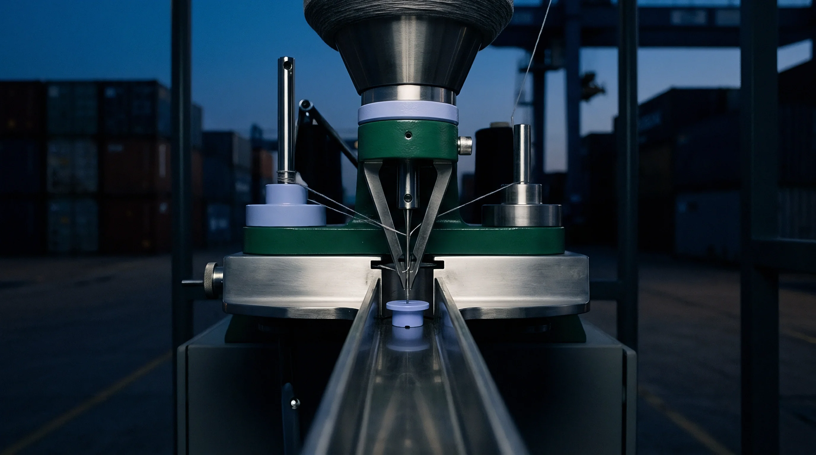
The venturi jet nozzle acts as both a chemical mass transfer interface and the mechanical drive unit for fabric transportation. High-pressure dye liquor forced through a constricted annular gap creates a localized low-pressure zone based on Bernoulli principle mechanics. This pressure differential draws the continuous fabric rope through the nozzle throat while surrounding yarn bundles with accelerated liquor.
The total pressure drop across the nozzle assembly comprises two distinct components: the acceleration head loss of the fluid passing through the narrow gap and the hydrodynamic drag loss imparted to the dense textile structure. Dense, heavy-weight woven cotton twills present significant physical resistance to liquor passage, increasing the overall hydraulic pressure drop across the throat. Light-weight micro-denier synthetic knits present less resistance, allowing higher fluid passage velocities at equivalent pump pressures.
Proper matching between nozzle gap distance, fabric weight, and pump pressure keeps fabric transport smooth and uniform across all chambers. Machine operators adjust the annular gap via threaded nozzle rings or motorized positioners to maintain constant fabric line speed without damaging delicate yarn structures.
| Nozzle Gap Size (mm) | Fabric Weight Class (g/m²) | Throat Velocity (m/s) | Pressure Drop (kPa) | Fabric Speed (m/min) |
|---|---|---|---|---|
| 1.5 | Lightweight (60 – 120) | 12.4 | 165 | 450 |
| 2.5 | Medium Weight (130 – 240) | 8.8 | 110 | 380 |
| 3.5 | Heavyweight (250 – 380) | 6.1 | 72 | 290 |
| 5.0 | Very Heavy / Fleece (>400) | 4.2 | 45 | 210 |
Fabric Load Impedance on Nozzle Hydraulics
When a vessel operates with uneven fabric load weights across chambers, local hydraulic loss profiles diverge immediately. A chamber loaded with 180 kilograms of cloth creates higher back-pressure at the nozzle throat than an adjacent chamber loaded with 140 kilograms. This additional mechanical impedance reduces local fluid flow rate through that specific nozzle, causing the main feed manifold to redistribute excess fluid volume toward the lighter-loaded chamber.
To establish controlled hydraulic boundaries across multi-chamber machinery, technical procurement specifications mandate strict parameter bounds. A formal machinery purchasing specification must detail the following engineering operational parameters:
- Annular Gap Calibration Tolerance specified within plus or minus 0.1 millimetres across all installed jet nozzles.
- Differential Pressure Measurement Accuracy rated for continuous high-temperature service up to 140 degrees Celsius with full digital transducer output.
- Maximum Permissible Chamber Flow Asymmetry defined at less than 3.0 percent deviation from mean flow rate under full nominal payload conditions.
- Individual Chamber Balancing Valve Seals rated for zero-leakage isolation against aggressive chemical baths at pH 2 to pH 12 operational ranges.
Closing the nozzle gap increases localized fluid shear stress, raising fabric transport velocity while simultaneously elevating total circuit back-pressure.
Disparity
Liquor Ratio Drift and Thermal Instability
Unequal hydraulic head losses across chambers lead directly to liquor ratio drift. In a multi-chamber jet dyeing machine, liquid continuously drains from individual vessel chambers into a shared bottom collector sump before re-entering the circulation pump. If Chamber 1 receives 500 litres per minute while Chamber 4 receives 580 litres per minute, the volume of bath residing inside Chamber 1 drops while liquid accumulates in Chamber 4.
This liquid height disparity alters the local liquor ratio within each tube. Chamber 1 operates at an effective short liquor ratio of 1:5, while Chamber 4 operates at a dilute liquor ratio of 1:7. Chemical concentration gradients form across the machine.
Dyestuffs whose exhaustion profiles display high sensitivity to electrolyte concentration or bath dilution exhaust faster in the low-volume chamber, producing permanent batch shade variation.
Thermal variance compounds chemical concentration differences. Liquid passing through the central heat exchanger enters the main delivery header at a uniform temperature. Chambers receiving lower fluid volume flows experience higher thermal dissipation rates through uninsulated vessel walls relative to high-flow chambers.
A temperature gradient of just 2.5 degrees Celsius during the critical dye migration window between 80 and 95 degrees Celsius alters disperse dye exhaustion kinetics on polyester, creating visible end-to-end and tube-to-tube shade off-shades.
Can Chamber Flow Equalization Eliminate Batch Metamerism?
Equalizing volumetric fluid flow across every chamber eliminates structural dye concentration variations during bulk exhaustion phases. Metamerism arises primarily when individual chambers absorb multi-dye recipes at varying relative rates, altering the final spectral reflectance curve of the finished fabric. When hydraulic head losses balance perfectly, dye exhaustion curves across all chambers synchronize, aligning color coordinates under varied light sources.
Achieving total color alignment requires matching mechanical fluid mechanics with specific fiber substrate characteristics. Variations in yarn twist, fiber crimp, and greige fabric porosity alter internal rope resistance inside the transport tube. Even with identical fluid delivery rates, differences in fabric hydraulic permeability induce subtle micro-environment shifts that influence dyestuff uptake rates.
A bath flow rate variance of seven percent shifts local chamber temperature profile rates by up to 3.2 degrees Celsius per minute during fast ramp thermal phases.
Whether dynamic flow control systems can continuously adapt to real-time changes in fabric porosity during synthetic fiber shrinkage cycles remains a subject of ongoing engineering research.
Diagnosis
Differential Pressure and Flow Verification Protocols
Identifying hydraulic loss distribution across multi-chamber dyeing systems requires structured diagnostic protocols. Instrumenting each chamber supply line with industrial magnetic flow meters and differential pressure transducers provides real-time verification of operational balance. Technicians execute baseline profiling using clean water prior to committing bulk textile goods to processing schedules.
- Fill the dyeing vessel with ambient water to the standard baseline liquid level indicator mark.
- Fully open all manual chamber throttling valves to establish unconstrained hydraulic baseline conditions.
- Engage the main circulation pump and incrementally ramp variable frequency drive output from 30 Hertz to 60 Hertz in 5-Hertz steps.
- Record static supply pressure, individual chamber feed pipe flow rates, and nozzle differential pressure at each step.
- Calculate individual chamber flow deviation percentages relative to calculated mean system volumetric delivery rates.
- Adjust individual chamber balancing valves until all flow readings sit within two percent of calculated mean system delivery.
- Repeat testing at 130 degrees Celsius operating temperature to verify thermal expansion stability and pressure sensor calibration.
Physical inspection complements digital sensor telemetry. Opening vessel chamber portals reveals physical liquid height discrepancies in return sumps, providing immediate visual confirmation of drainage piping restrictions or return line hydraulic imbalance.
Standards and Verification Documentation
International standard ISO 2267 defines testing parameters for textile machinery liquor circulation systems. Adherence to standard verification criteria protects buyers against machinery manufacturing flaws that impair shade levelness across production runs.
| Standard Reference | Target Parameter | Acceptable Operating Limit | Diagnostic Method |
|---|---|---|---|
| ISO 2267 Sec 4.2 | Chamber Flow Symmetry | Within +/- 2.5% of mean flow | In-line electromagnetic flowmeter |
| ISO 13937 Part 1 | Nozzle Pressure Drop Symmetry | Max 5.0 kPa variation across nozzles | Differential pressure transmitter array |
| DIN 22801 | Header Static Pressure Profile | Max 3.0% recovery variation along axis | Multi-point digital piezometer ring |
| ASTM E2533 | Thermal Bath Uniformity | Within +/- 0.5 deg C across chambers | Calibrated RTD sensor insertion array |
Purchase contracts incorporating ISO 2267 machinery acceptance clauses allow mill owners to reject delivery of multi-chamber dyeing machinery if flow distribution variance between individual chambers exceeds three percent during factory acceptance trials.
Remedy
Mechanical Balancing and Process Window Optimization
Correcting hydraulic head loss disparities across multi-chamber dyeing machinery demands a combination of hardware modifications and refined operational protocols. Installing high-precision manual or automated globe balancing valves on individual chamber feed branches provides the primary mechanical lever for flow equalisation. Technicians throttle high-flow downstream chambers, adding artificial friction that compensates for manifold static pressure recovery.
Upgrading main pump control strategies further improves system performance. Operating centrifugal pumps via variable frequency drives allows precise matching of system dynamic head against specific fabric style resistance profiles. Rather than running the pump at fixed maximum output and relying on heavy valve throttling, operators adjust pump speed to hit optimal fluid velocity thresholds without generating excessive turbulent head loss.
| Fabric Construction | Target Flow Velocity (m/s) | Optimal Pump VFD Frequency (Hz) | Nozzle Gap Target (mm) | Max Flow Variance (%) |
|---|---|---|---|---|
| Lightweight Warp Knit | 1.8 to 2.2 | 42 to 46 | 2.0 | 1.5 |
| Medium Single Jersey | 2.3 to 2.7 | 48 to 52 | 2.8 | 2.0 |
| Heavy French Terry | 2.8 to 3.2 | 54 to 58 | 3.5 | 2.5 |
| High-Density Woven Nylon | 3.0 to 3.5 | 56 to 60 | 1.8 | 2.0 |
Implementing targeted process boundaries reduces re-dyeing rates on multi-chamber machines. A comprehensive operational decision protocol guides floor technicians through daily setup adjustments:
- Fabric Weight Verification requires weighing each rope segment prior to vessel loading to ensure chamber mass loading symmetry within 2.0 percent.
- Nozzle Gap Standardisation commands monthly feeler-gauge inspection of all jet throats to prevent mechanical drift caused by operational vibration.
- Filter Basket Maintenance dictates cleaning internal lint screens every two batch cycles to prevent asymmetrical return-line head losses.
- Automated Valve Calibration mandates zero-point verification of electronic control valves at every scheduled quarterly maintenance window.
Matching system hydraulic characteristics to fabric structural mechanics stabilizes bulk processing parameters. Correcting pressure drops across manifolds, maintaining tight nozzle gap tolerances, and verifying equal volumetric delivery per chamber eliminates the physical drivers of shade unlevelness. System balancing reduces chemical consumption, minimizes thermal energy requirements, and secures consistent batch-to-batch color repeatability across complex multi-chamber dyeing operations.