Nozzle Hydraulic Pressure Calibration for Jet Dyeing Dense Woven Fabrics
Dynamic nozzle pressure calibration balances liquor velocity and fabric rope speed, preventing mechanical chafe and shade streakiness on dense woven fabrics.
Nozzle
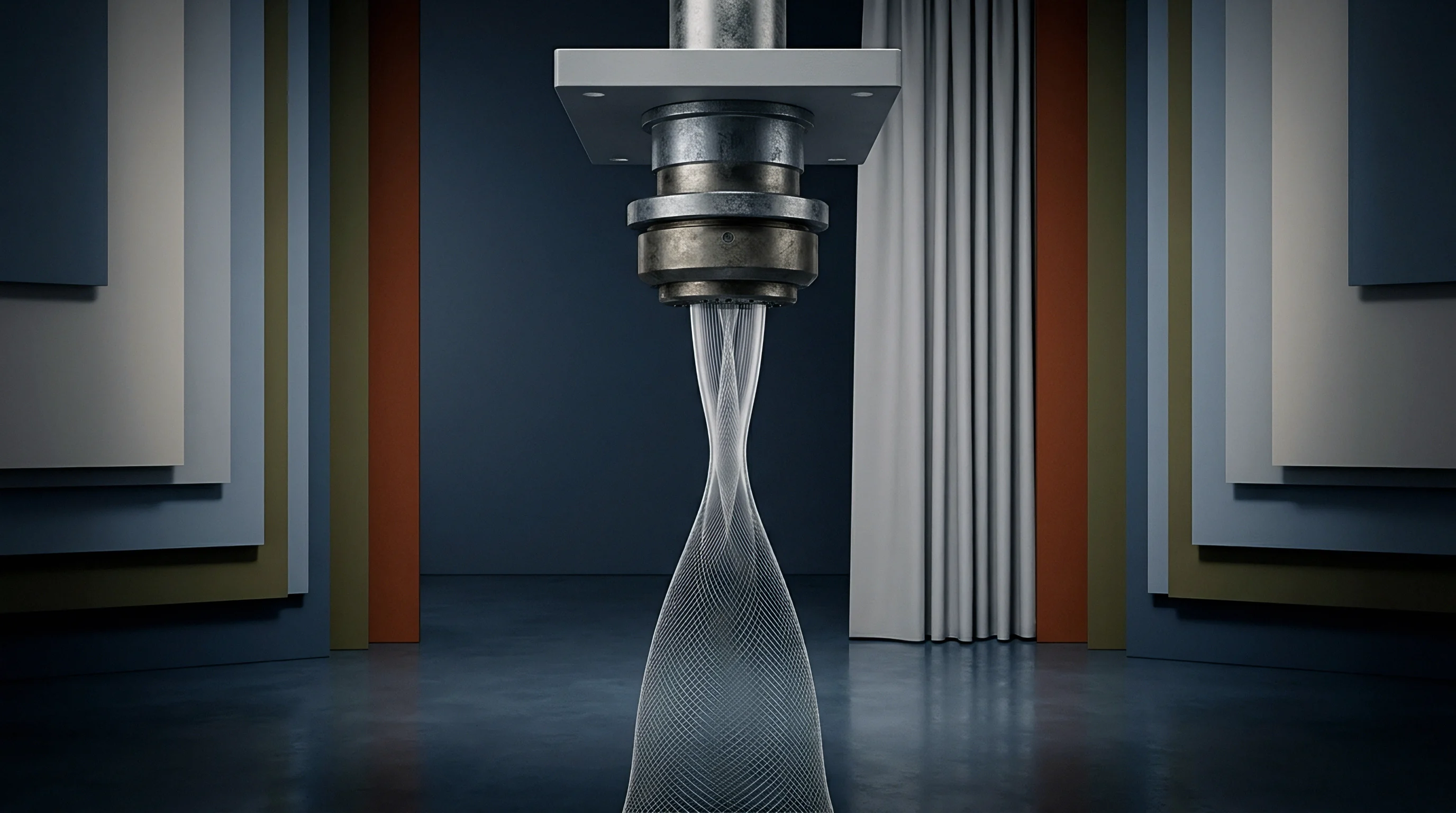
Tight warp and fill packing makes high-density woven substrates difficult to penetrate during rope-form wet processing. Fabrics like 300T downproof nylon taffeta, 140 gsm high-sett polyester micro-filaments, and 133 × 72 combed cotton poplin offer minimal inter-yarn porosity. Inside a jet dyeing machine, fluid interaction in the venturi throat determines whether dye liquor penetrates the core of the bundle or merely sweeps across the surface.
Hydrodynamic energy must move the strand cleanly without causing mechanical chafe or filament shear.
Kinetic energy transfers from the liquor to the fabric via wall friction and dynamic pressure drops across the venturi constriction. Total driving force combines wall pressure drag with momentum from the high-velocity jet. While open knits let liquor pass through easily and dissipate excess kinetic energy, dense wovens act like hydraulic shields.
When the liquid jet hits the compressed fabric wall, fluid momentum deflects sideways, generating local turbulence that forces the bundle against the nozzle walls.
Selecting internal venturi diameter comes down to balancing transport speed against mechanical shear. Changing insert sizes between 80 mm and 160 mm shifts fluid velocity at identical pump flow rates. Under Bernoulli’s principles for incompressible flow, a smaller nozzle increases throat velocity and kinetic drag, pulling the fabric faster.
On tight 300T polyester microfibers, however, excessive liquor velocity creates enough friction to misalign filaments, leading to surface fuzzing and micro-creasing.
Installing a wider insert lowers fluid velocity and relieves shear, but introduces the risk of transport stagnation. Because the dense bundle resists fluid penetration, any drop in hydraulic driving pressure below the threshold needed to counter fabric weight and pipe drag can stall the rope inside the transport tube. Once stalled, stationary sections take the full force of high-energy streams, leaving distinct abrasion marks and uneven dyeing.
The dynamic pressure drop measured across the venturi throat must maintain a stable ratio relative to fabric line speed to prevent surface chafing on high-sett filament fabrics.
Sizing nozzle clearance accurately requires evaluating fabric weight, strand volume, and physical density together. Operators typically measure rope diameter under light tension to pick the right insert. Under tension, dense wovens pack into a significantly tighter cross-section than knits of equivalent areal weight.
An oversized throat lets liquor bypass the strand, losing hydraulic energy and dropping line speed. An undersized throat pinches the bundle, setting sharp creases that become permanent during high-temperature cycles.
| Fabric Construction | Weight (g/m²) | Sett (Ends/cm x Picks/cm) | Nozzle Diameter (mm) | Differential Pressure (bar) | Liquor Velocity (m/min) |
|---|---|---|---|---|---|
| Nylon 6,6 Downproof Taffeta | 38 | 160 x 110 | 100 | 0.35 – 0.45 | 380 – 420 |
| Polyester Microfiber Plain Weave | 85 | 120 x 85 | 110 | 0.40 – 0.50 | 320 – 360 |
| Cotton Poplin Mercerized | 135 | 52 x 28 | 130 | 0.50 – 0.65 | 250 – 280 |
| Polyester/Cotton Twill 3/1 | 220 | 42 x 24 | 140 | 0.60 – 0.75 | 200 – 240 |
| Heavy Nylon Cordura Woven | 340 | 22 x 15 | 150 | 0.70 – 0.85 | 160 – 190 |
| Data recorded under steady-state fluid circulation at 130°C for synthetics and 98°C for cotton blends with a 1:8 liquor ratio. | |||||
Liquor ratio selection directly affects pressure dynamics throughout the circulation loop. Running dense wovens at ultra-short ratios between 1:4 and 1:6 restricts fluid volume inside the venturi, raising the odds of air entrainment and static pressure spikes. Maintaining a moderate 1:8 to 1:10 ratio preserves a continuous fluid sleeve around the fabric rope as it clears the nozzle, shielding delicate filament yarns from direct contact with the stainless steel housing and keeping differential pressure stable.
Evaluating nozzle pressure distribution requires installing pressure transducers immediately upstream and downstream of the venturi convergence zone. Tracking differential pressure (Δ Pn) gives a direct reading of hydraulic resistance and rope packing density. High differential values flag excessive fabric compaction in the throat and imminent mechanical abrasion, while low readings point to fluid bypass where liquor fails to transfer sufficient momentum to sustain cycle times.
Using the wrong venturi insert diameter on a 300T polyester microfiber weave frequently triggers surface filament shear and edge-to-center shading, turning entire production lots into scrap.
Cavitation
Localized drops in static pressure within the circulation loop can provoke rapid phase changes, generating micro-bubbles of water vapor. When high-temperature liquor passes through a restricted venturi throat, fluid velocity peaks while static pressure plunges. If that pressure dips below the liquor’s saturated vapor pressure at operating temperature, vapor cavities nucleate immediately.
As these bubbles enter the wider divergence zone downstream, recovering static pressure causes them to collapse with substantial force.
Shockwaves from collapsing cavities produce intense micro-jet impacts. In jet machines running at 130°C, these shockwaves hit the dense woven strand right as it emerges from the nozzle throat. The resulting implosions strip synthetic filaments, fracture staple fiber tips, and generate surface pilling that looks like permanent shade frosting.
Micro-denier synthetics are especially vulnerable, showing visible warp-direction frosted streaks after brief exposure to cavitating flow.
Net Positive Suction Head available (NPSHa) at the pump inlet governs whether cavitation takes root. Processing high-density cotton poplins at 98°C or polyester weaves at 130°C already pushes fluid close to its vapor pressure; aggressive impeller speeds drop inlet suction pressure further. If available head falls below the pump manufacturer’s required threshold (NPSHr), micro-cavitation initiates inside the casing and migrates into the delivery line and nozzle manifold.
ISO 105-X12 tests for rubbing fastness show a minimum half-grade drop on dense woven polyesters when dyed under cavitation-induced hydraulic turbulence.
Micro-foam generation worsens shear damage during cavitation events. Auxiliary chemistries like leveling agents, dispersants, and alkali buffers lower bath surface tension, stabilizing micro-bubbles formed during pressure drops. When these foam pockets pass through the venturi throat, they disrupt continuous fluid delivery and trigger hydraulic pulsing.
Erratic jerks on the fabric rope create prominent rope marks and diagonal chafe lines that cannot be removed during downstream heat setting.
Relying on maximum pump drive frequencies to push heavy, dense loads through tight nozzles invariably induces cavitation. Mills often raise pump speeds to clear rope sluggishness without accounting for how that frequency shift depresses static pressure at the throat inlet. Resolving cavitation requires balancing pump inverter output against throttle valve trim and nozzle insert bore, keeping local static pressure comfortably above vapor pressure across the entire temperature profile.
Technicians frequently attribute chafe marks on high-density weaves to missing bath lubricants rather than addressing the underlying hydraulic conditions causing the damage.
Velocity
Dynamic liquid displacement speed controls the kinetic energy transferred from the bath to the advancing fabric rope. Analyzing dynamic pressure and fluid speed requires examining both volumetric flow rate and throat geometry. Fluid velocity (Vl) through a circular venturi orifice follows pump output (Q) and throat area (A) according to standard flow relations.
For dense wovens, matching this velocity to fabric strand speed (Vf) ensures effective hydrodynamic drag without inducing slippage or abrasive shear.
Hydrodynamic drag force (Fd) acting on the strand scales with the square of the relative velocity between the liquid jet and the rope, defined by:
Fd = frac12 ρ Cd A (Vl – Vf)2
Here, ρ is liquor density, Cd is the fabric surface friction coefficient, A is effective contact area, Vl is liquid velocity, and Vf is fabric line speed. A controlled degree of relative velocity (Vl – Vf) produces the driving force necessary to lift dense, wet yardage out of the J-box and over the reel.
Why Does Nozzle Orifice Selection Dictate Hydrodynamic Drag?
Because throat cross-section changes velocity quadratically at fixed volumetric flow rates, nozzle selection sets hydraulic boundary conditions. A tight 100 mm insert accelerates liquor sufficiently to propel lightweight, dense nylon fabrics beyond 400 meters per minute. However, elevated relative velocity increases boundary-layer friction losses (Cd).
On heavier goods like 220 gsm poly-cotton twills, excessive relative speed causes liquor to shear past the bundle without transferring linear momentum, scouring the surface and breaking filament bundles.
The slip ratio (S) expresses this hydraulic power transfer efficiency:
S = fracVl – VfVl
Dense woven processing runs best within a slip ratio range of 0.15 to 0.25. Ratios above 0.35 mean liquor is blowing past the rope, abrading surface fibers while the fabric lags. Conversely, a slip ratio under 0.10 indicates hydraulic choking; the rope moves almost in lockstep with the fluid, dampening the exchange needed for dye to penetrate tightly crossed warp and weft yarns.
Maintaining a slip ratio below 0.25 on high-sett synthetic weaves eliminates surface filament fuzzing while maintaining required rope cycle times.
Calibrating dynamic hydraulic pressure on jet equipment follows a structured five-step procedure:
- Mount high-precision piezoelectric pressure transducers into the sampling ports positioned 50 mm upstream and 50 mm downstream of the venturi nozzle throat.
- Fill the machine with clean water, establish target liquor ratio, heat the bath to 80°C, and zero digital differential pressure indicators.
- Set the main circulation pump variable frequency drive to 30 Hz, measure baseline static pressure, and verify transducer signal linearity across digital controller inputs.
- Increment pump frequency in 5 Hz steps up to 50 Hz, recording dynamic differential pressure, pump motor power draw, and total volumetric flow rate from the inline electromagnetic flow meter at each interval.
- Load the target dense woven fabric batch, synchronize mechanical reel speed with measured fabric strand velocity using an optical tachometer, and adjust pump frequency drive until differential pressure aligns with calculated hydrodynamic drag targets.
| Machine Jet Type | Nozzle Geometry | Max Pump Head (bar) | Target Slip Ratio | Typical Fabric Speed (m/min) | Fabric Density Suitability |
|---|---|---|---|---|---|
| High-Pressure Circular Jet | Concentric Venturi | 2.8 – 3.5 | 0.18 – 0.22 | 350 – 450 | Ultra-Dense Synthetics (<100 g/m²) |
| Soft-Flow Long Tube Jet | Elliptical Annular | 1.5 – 2.2 | 0.20 – 0.25 | 200 – 300 | Medium Dense Blends (100-220 g/m²) |
| Overflow Dyeing Jet | Gravity Cascade | 0.8 – 1.2 | 0.30 – 0.40 | 80 – 150 | Heavy Cotton Twills (>220 g/m²) |
| Air-Jet Hybrid Machine | Biphase Air/Liquor | 3.0 – 4.2 | 0.12 – 0.16 | 400 – 550 | Micro-Denier Downproof Weaves |
In one diagnostic calibration on a 4-tube vessel running a 280 gsm cotton-nylon canvas, a mill faced recurring warp streakiness and tube-to-tube shade mismatches. The machine was set up with 110 mm inserts and a 48 Hz pump speed, generating 0.82 bar differential pressure and a liquor velocity of 420 meters per minute. Reel speed had been dialed back to 210 meters per minute to prevent tangling, which produced a slip ratio of 0.50.
High liquor velocity combined with this excessive slip abraded the weave and stripped dye chemistry off outer fibers. Opening nozzles to 140 mm, adding lubricant, and reducing pump output to 38 Hz brought differential pressure down to 0.48 bar, reduced liquor speed to 260 meters per minute, and brought the slip ratio to 0.19, eliminating streakiness in subsequent runs.
Matching liquor displacement rate to fabric circulation speed prevents rope slippage without distorting high-density weave construction.
Manifold
The distribution header routes total pump output into parallel jet lines across multi-tube vessels. In 4-tube and 6-tube machinery, frictional head losses along the manifold create unequal pressure drops across individual nozzles unless piping is balanced against flow resistance. Maintaining uniform delivery pressure across every port is essential for consistent dyeing across all ropes.
Fittings, directional elbows, and tee-junctions sap static head along the manifold length. As a result, chambers positioned near the pump discharge receive higher pressure than those at the far end of the header. When Chamber 1 runs at 0.55 bar differential and Chamber 4 drops to 0.42 bar, strand velocities and bath turnover rates diverge across the vessel.
Low-pressure tubes see fewer cycles per minute, yielding heavier shade build-up and noticeable tube-to-tube shade variations across the lot.
Compensating for line losses requires balancing valves and independent digital flow meters on each chamber feed pipe. Balancing the vessel involves equalizing dynamic head across every port under actual load. Operators log differential pressures simultaneously across all nozzles using multi-channel digital manometers, adjusting manual or actuated header valves until tube-to-tube variance sits within a 0.02 bar window.
Chamber-to-chamber pressure variations exceeding 0.03 bar across a multi-tube jet vessel generate statistically significant color differences exceeding 0.8 DELTA E CMC on dense polyester fabrics.
Hydraulic imbalance across multi-chamber systems typically produces several distinct processing defects on dense wovens:
- Tube Strand Desynchronization, where variable hydraulic drag forces cause individual fabric strands across parallel chambers to complete cycle turnarounds at different rates, producing batch-to-batch color yield variations.
- Localized Hydrodynamic Choking, where reduced static head in terminal chambers fails to push high-density fabric strands through venturi constrictions, leading to fabric accumulation and safety knockout sensor triggers.
- Differential Liquor Turnovers, where variable fluid volume delivery alters local dye bath exhaustion kinetics, causing shade depth mismatches between rolls dyed in adjacent tubes.
- Asymmetric Boundary Abrasion, where chambers operating under excessive static head induce high fluid shear that dulls fabric surface luster compared to strands processed in low-pressure chambers.
Heating the bath to 130°C alters hydraulic balance as liquor expands and dynamic viscosity drops. Water density declines from 1000 kg/m³ at 20°C to roughly 935 kg/m³ at 130°C. Lower viscosity reduces straight-pipe wall friction but amplifies secondary turbulence at manifold tee-junctions. Consequently, balancing performed at room temperature rarely holds at full dyeing temperature; differential pressure stability must be verified throughout the heating ramp from 40°C up to the 130°C hold.
Whether automated digital flow splitters can fully eliminate operator variation in valve positioning remains an active debate among plant engineering teams.
Audit
Auditing dyehouse calibration requires reconciling sensor logs with physical fabric performance. Sourcing programs placing dense woven goods with commission dyehouses must inspect hydraulic maintenance and pressure transducer reliability directly on the floor. Trusting control screen readouts without auditing physical calibration routines leaves buyers exposed to high rejection rates on tightly woven programs.
Verification starts with calibration certificates for onboard pressure transducers, flow meters, and inverter drives. Piezoelectric sensors drift under sustained thermal cycling, chemistry exposure, and vibration. A sensor reading 0.50 bar on screen can easily be running at an actual 0.38 bar or 0.62 bar if zero-point and span checks are skipped.
Dyehouses need to run routine dead-weight or master-gauge recalibrations every six months and archive those traceable records for audits.
Unchecked sensor drift routinely leads to rejected lots. A thorough technical qualification confirms that a mill controls its hydraulic parameters before bulk commitments begin.
- Transducer Recalibration Logs, confirming six-month sensor verification against certified master reference pressure gauges.
- Nozzle Profile Inventory, verifying availability of machine-matched venturi inserts spanning 90 mm to 160 mm diameters to accommodate varying fabric weight ranges.
- Header Balance Records, documenting chamber-to-chamber differential pressure variance within a maximum 0.02 bar tolerance window under full load.
- Pump Inverter Linearity Charts, validating motor frequency response against digital volumetric flow meter outputs across 20 Hz to 50 Hz operational bands.
- Fabric Speed Sync Protocols, demonstrating automated reel-to-nozzle velocity synchronization to maintain target slip ratios on micro-denier woven orders.
| Calibration Failure Mode | Physical Defect Manifestation | Direct Scrap / Re-work Rate (%) | Landed Cost Impact ($/Metre) | Production Schedule Delay |
|---|---|---|---|---|
| Uncalibrated Differential Pressure | Rope Chafe & Filament Fuzzing | 4.5 – 8.0 | 0.35 – 0.65 | 2 – 3 Weeks (Re-weaving) |
| Multi-Tube Manifold Imbalance | Tube-to-Tube Shade Variation | 6.0 – 12.0 | 0.45 – 0.85 | 1 – 2 Weeks (Color Stripping) |
| Venturi Cavitation Turbulence | Surface Frosting & Pilling | 3.0 – 5.5 | 0.25 – 0.40 | 1 Week (Enzyme Defuzzing) |
| High Slip Velocity Ratio (>0.35) | Warp Crease Marks & Streaks | 8.0 – 15.0 | 0.60 – 1.20 | 3 Weeks (Full Batch Scrap) |
Incorporating explicit technical tolerances into purchasing specifications provides clear quality protection. Contracts should define firm limits for surface friction, shade levelness (Δ ECMC le 0.60), and post-dye dimensional stability to avoid ambiguity around finished goods acceptance.
Commission dyeing contracts containing explicit nozzle differential pressure tolerances reduce bulk shade dispute resolution timelines from months to days.
Enforcing a contract clause that requires all jet machines running high-density wovens to hold nozzle differential pressure variance within plus or minus 0.02 bar of approved lab parameters gives brands clear grounds to reject off-shade or surface-damaged production.