Mitigating Inter Chamber Shade Disparities from Parallel Nozzle Pressure Variations in Multi Tube Dyeing Vessels
Equalizing parallel nozzle pressure across multi-tube jet vessels eliminates inter-chamber shade variations by balancing rope speed and liquor turnover.
Manifold
Fluid Dynamics across Parallel Pressure Lines
Dyeing vessels running parallel displacement tubes depend on balanced hydraulic energy from a single circulation pump. When an industrial jet or overflow machine processes four, six, or eight ropes simultaneously, liquor splits from the main delivery pipe into branch lines feeding each venturi jet assembly. In an unmetered header pipe, static pressure drops progressively along the line as fluid exits through successive branch outlets.
Friction along pipe walls and turbulent energy loss at each tee junction combine to create an uneven static head across the nozzle bank.
Central tubes nearest the pump discharge receive higher fluid velocities and static pressure. Terminal chambers at the closed end of the header see reduced static head and lower volumetric flow rates. While high velocity through a jet orifice creates the suction that pulls textile rope through the nozzle and forces liquor into the bundle, lower velocity in terminal lines reduces mechanical traction, slowing transit speeds and lengthening cycle turnaround times for that specific rope.
A four-thousand-metre production run of 240 grams per square metre cotton-polyester 60/40 knitted single jersey shows how directly these mechanical disparities affect final shade consistency. Ropes in central chambers completed a full circulation loop every fifty-two seconds, while those in outer terminal chambers took sixty-eight seconds per pass. Over a ninety-minute exhaustion cycle, fabric in central chambers passed through the active nozzle zone one hundred and three times compared to seventy-nine passes for fabric in outer chambers.
That twenty-four percent reduction in nozzle contacts fundamentally changes the dye bath exchange rate per unit weight of goods.
Maintaining uniform liquor ratios requires fluid volume in each chamber to match the weight of the loaded rope. In practice, terminal nozzles running at lower pressures receive less liquor per minute. If the main pump delivers four thousand litres per minute across a four-tube machine, balanced operation requires one thousand litres per minute per tube.
System friction losses frequently drop terminal tube delivery to eight hundred and twenty litres per minute, while central tubes take one thousand one hundred and eighty litres per minute. This shifts the nominal 10:1 liquor ratio down to 8.2:1 in terminal positions and up to 11.8:1 in the center.
Main circulation pumps operating at 1,450 revolutions per minute generate a differential pressure drop of 0.42 bar between central take-off branches and terminal nozzle feeds in unmetered four-chamber vessels.
Chemical kinetics in exhaust dyeing respond immediately to shifts in local liquor ratios. High-substantivity dyes exhaust faster at lower ratios owing to the steeper concentration gradient between bath and fiber. Reactive dyes on cellulosic fibers show accelerated exhaustion and higher initial fixation rates in terminal chambers running at reduced liquor volumes.
Disperse dyes on synthetic fibers in the same machine exhibit altered levelling behavior, as heat transfer between liquor and bundle depends directly on fluid velocity through the transport tube.
Field evaluations in Ningbo traced hydraulic head loss in jet machines. Physical measurements taken at nozzle entry ports confirmed that static pressure dropped by 0.38 bar between tube two and tube four during peak bath circulation. Spectrophotometric analysis of the finished goods showed a colour difference calculation of 1.42 units under D65 illumination between those two chambers.
The central chambers produced darker, redder swatches, while the outer chambers yielded lighter, bluer swatches from the exact same dye bath mix. Unequal mechanical pressures delivered different chemical exposures to identical material batches.
Mechanical Geometry of Main Supply Headers
Header layout geometry largely dictates how severe hydraulic imbalances become across parallel nozzle arrays. Standard vessels often use a straight cylindrical header of uniform diameter from pump inlet to end cap. Fluid moving past a right-angle branch outlet retains forward momentum, creating a vena contracta at the entrance of each branch pipe.
The effective cross-sectional area contracts, raising local flow resistance and producing pressure drops that vary with distance from the pump discharge.
Tapered headers counter static pressure losses by stepping down the main pipe cross-section after each branch take-off. As total fluid volume in the header decreases, reducing pipe diameter maintains fluid velocity along the manifold length. In line with Bernoulli’s energy balance equations, constant velocity preserves static head, narrowing the pressure gap between the first and last nozzle take-offs.
Retrofitting straight headers with stepped internal reductions stabilizes branch inlet pressures across active jet channels.
Internal pipe wall roughness also contributes to cumulative head loss over extended operation. Chemical precipitation, oligomer deposits from polyester processing, and calcium carbonate scale gradually narrow the effective internal diameter of supply lines. This deposition rarely happens evenly: outer branches with lower baseline flow velocities accumulate thicker scale than high-velocity central branches.
Uneven fouling increases hydraulic resistance in already starved terminal lines, amplifying shade disparities as machinery ages.
Pressure differentials below half a bar are often treated as acceptable engineering tolerances, with resulting shade variance attributed instead to substrate weight fluctuations across the batch.
Hydraulics
Quantifying Flow Rate Variance and Dye Exhaustion Rates
Variations in transport velocity directly alter how frequently textile fibers encounter concentrated dye liquor. Exhaust systems rely on repeated contact between the liquor stream and moving rope to achieve uniform migration and strike rates. When parallel nozzles operate at different delivery pressures, dye transfer kinetics cease to behave as a steady-state process and become chamber-dependent.
Differential pressure across a jet nozzle governs both the fluid velocity impinging on the cloth and the speed at which the rope travels through the transport tube. Linear rope velocity correlates with the square root of the pressure drop across the nozzle orifice. Reducing nozzle pressure from 2.5 bar to 1.8 bar drops rope speed from 350 metres per minute to 296 metres per minute.
In a vessel holding three hundred metres of fabric per chamber, that pressure drop extends single-loop transit time from 51.4 seconds to 60.8 seconds. Over a sixty-minute fixation phase, the slower rope completes ten fewer passes through the active liquor zone.
Fewer bath contacts per minute slow the exhaustion rate of medium-to-high affinity dyes. During initial migration, dyes dissolve in the bath and adsorb onto fiber surfaces. Equal liquor distribution across all chambers ensures that the concentration of unexhausted dye drops at an identical rate across all ropes.
If one chamber receives lower flow rates, local dye depletion occurs rapidly within the stagnant boundary layer surrounding the slow-moving rope. The concentration gradient driving dye into the fiber matrix flattens, slowing overall uptake compared to chambers receiving higher fluid turnover.
Installing symmetrical venturi inserts reduced shade variance from ΔE 1.84 down to ΔE 0.38. This modification equalized fluid delivery rates within a maximum tolerance band of plus or minus two percent across all four processing tubes. Prior to installation, terminal chambers consistently yielded lighter shade depths due to insufficient liquor exchange during the fast-exhaustion window of reactive trichromatic formulations.
| Chamber ID | Nozzle Pressure (bar) | Rope Speed (m/min) | Turnover Time (s) | Liquor Ratio | Shade Shift (CMC 2:1 ΔE) |
|---|---|---|---|---|---|
| Chamber 1 (Inlet End) | 2.45 | 348 | 51.7 | 11.2:1 | 0.12 (Base Reference) |
| Chamber 2 (Center-Left) | 2.50 | 352 | 51.1 | 11.5:1 | 0.28 (Slightly Darker) |
| Chamber 3 (Center-Right) | 2.30 | 335 | 53.7 | 10.4:1 | 0.45 (Acceptable) |
| Chamber 4 (Terminal End) | 1.95 | 308 | 58.4 | 8.8:1 | 1.38 (Out of Spec) |
| Data recorded during reactive dye application at 60 degrees Celsius with a nominal 1,000 kg machine payload divided into 250 kg ropes per chamber. | |||||
Physical Drivers of Internal Pressure Drops
Pipe surface friction coefficients change over operational lifecycles as chemical scale accumulates inside supply branches. Energy loss inside multi-tube dyeing machines stems from three distinct sources within the piping system: pipe wall skin friction, fitting resistance at elbows and tees, and dynamic backpressure generated by the textile rope inside the venturi throat.
Skin friction along internal pipe walls follows the Darcy-Weisbach equation, where head loss increases proportionally with the square of fluid velocity and inversely with internal pipe diameter. In high-capacity machines pumping four thousand litres per minute, fluid velocities inside supply manifolds often exceed four metres per second. At these speeds, minor variations in wall roughness or small internal weld seams generate significant turbulent eddies that convert kinetic energy into thermal energy, dropping static head pressure upstream of nozzle orifices.
Fitting resistance at branch junctions creates localized pressure drops through flow separation. When liquid moving along the primary header turns ninety degrees into a nozzle feed pipe, a zone of turbulent recirculation forms at the inner radius of the bend. This flow separation narrows the effective path of the liquid, causing a sudden pressure drop across the junction.
Secondary feed pipes welded flush to the main header wall generate larger flow separation zones than radius-contoured branch take-offs or 45-degree lateral fittings.
Rope bulk density inside the nozzle throat creates dynamic backpressure that alters pump performance. Heavy woven substrates like 350 gsm cotton canvas fill the cross-sectional area of the venturi throat completely, restricting surrounding liquid flow. Lightweight knitted substrates like 120 gsm nylon tricot leave open space around the rope, allowing liquid to bypass the bundle freely.
Loading individual chambers with unequal fabric weights or varying rope lengths shifts nozzle backpressure dynamically, forcing liquid toward chambers offering the lowest physical resistance.
- Asymmetric Manifold Geometry creates unequal path lengths and varying junction angles between the main circulation pump discharge and individual venturi jet assemblies.
- Differential Internal Scaling restricts cross-sectional pipe areas in low-velocity terminal branches through progressive chemical precipitate accumulation over operational cycles.
- Unbalanced Rope Loading changes physical packing density inside individual venturi throats, generating variable dynamic backpressure across parallel processing channels.
- Unequal Nozzle Orifice Wear alters the calibrated aperture dimensions, causing identical fluid pressures to produce differing volumetric discharge rates between chambers.
- Branch Line Friction Disparities arise from sharp-angled welded junctions that induce localized turbulent eddies and fluid separation zones.
Proper maintenance requires regular inspection of internal pipe walls and mechanical fittings. Routine site audits inspect the internal pipe walls of parallel manifold headers for calcification build-up. Detecting scale formation early prevents irreversible hydraulic drift between maintenance intervals.
Small physical defects inside the manifold cascade into major commercial rejections. Unbalanced pressure distributions cause shade variations that remain hidden until finished rolls are unrolled on visual inspection tables or cut into garment panels.
A single re-dyeing run on four tons of unevenly shaded fleece incurred twenty-eight thousand dollars in airfreight charges to meet a retail distribution deadline.
Hardware
Which Hydraulic Adjustments Eliminate Chamber Disparity?
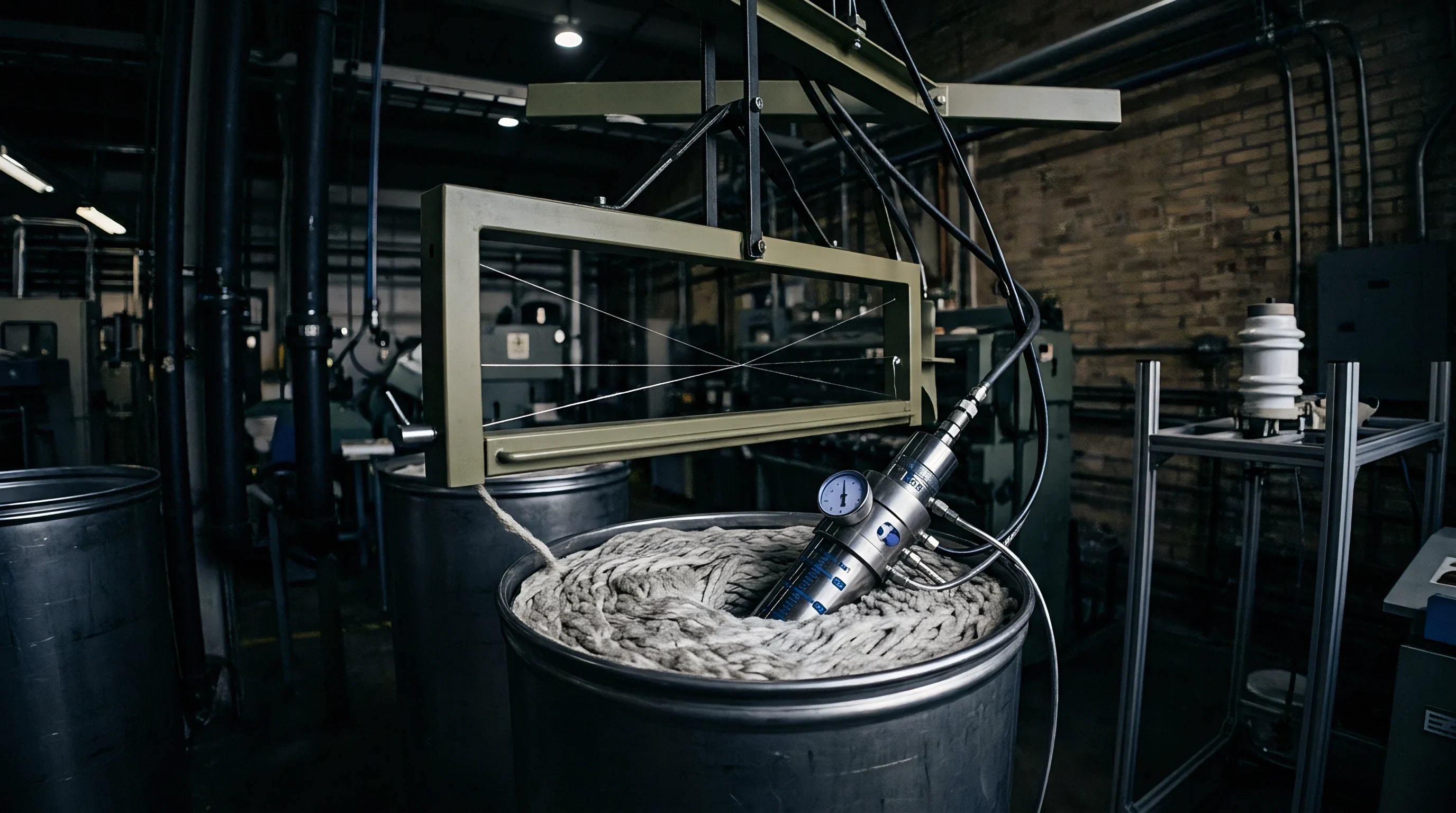
Mounting pressure transducers upstream of each venturi jet allows technicians to track dynamic head differentials in real time. Continuous digital monitoring replaces assumptions with empirical hydraulic data across all active lines. When pressure sensors detect a deviation exceeding 0.05 bar between any two processing tubes, automated balance valves adjust fluid flow to restore uniform pressure across the header.
Motorized ball valves or diaphragm control valves installed on each branch line regulate fluid delivery based on feedback from downstream pressure sensors. If terminal chamber four shows a pressure drop, the automated control system throttles back supply valves on central chambers one and two. Throttling central lines increases system backpressure, redirecting fluid flow toward terminal lines until all sensors report identical static head values.
This dynamic balancing maintains equal liquor ratios and uniform rope speeds regardless of minor differences in fabric weight or pipe friction.
Static balancing rings inserted into branch lines offer a mechanical alternative to automated control valves. Orifice plates machined to specific internal diameters balance hydraulic resistance across the manifold. Placed inside feed pipes of high-pressure central chambers, orifice plates restrict flow just enough to match the natural friction loss experienced by terminal lines.
Selecting precise orifice dimensions requires fluid flow calculations based on maximum pump discharge rates and liquor viscosities at operating temperatures.
Symmetrical ring manifold architectures eliminate branch length variations entirely. Instead of a single header pipe with sequential branch outlets, a ring manifold splits fluid flow from the primary pump into two equal supply loops feeding a circular distribution pipe. Branch lines connect to the circular pipe at mathematically symmetrical intervals.
Liquid enters nozzle assemblies from two opposing directions simultaneously, cancelling out velocity vectors and delivering identical static pressure to every active chamber in the machine.
Balancing Manifolds through Orifice Metering and VFD Controls
Calibrated throttling valves in secondary feed lines regulate line resistance to achieve uniform fluid delivery. Variable Frequency Drives (VFD) connected to primary circulation pump motors provide additional control over total fluid kinetic energy. Running main pumps at fixed rotational speeds often forces technicians to throttle main outlet valves to prevent fabric damage on delicate substrates.
Throttling the main valve wastes electrical energy and accentuates pressure imbalances across branch lines.
Lowering motor frequency via a VFD reduces total volumetric flow while maintaining optimal system head pressure. Modern jet vessels combine VFD motor control with adjustable nozzle orifice gaps. Operators adjust internal throat diameters from 50 millimetres up to 140 millimetres using mechanical adjustment rings.
Expanding the throat diameter in high-pressure chambers reduces local fluid velocity and backpressure, while narrowing it in low-pressure chambers increases local fluid velocity and rope driving force.
| Intervention Type | Mechanical Modification | Pressure Tolerance | Capital Cost Range (USD) | Shade ΔE Reduction |
|---|---|---|---|---|
| Manual Orifice Metering | Machined restriction plates inside branch pipes | ± 0.10 bar | 500 – 1,500 | 0.85 to 0.42 |
| Motorized Control Valves | Closed-loop automated balancing valves per tube | ± 0.02 bar | 8,000 – 18,000 | 1.45 to 0.18 |
| Tapered Header Manifold | Progressive internal diameter reduction of main pipe | ± 0.05 bar | 3,500 – 7,000 | 1.10 to 0.25 |
| Symmetrical Ring Piping | Dual-loop circular fluid supply manifold design | ± 0.01 bar | 12,000 – 25,000 | 1.60 to 0.12 |
- Isolate the main circulation pump and drain all residual liquid from the primary supply manifold and secondary branch lines.
- Mount calibrated digital pressure transducers on the inspection ports located immediately upstream of each nozzle inlet housing.
- Fill the vessel with clean water to the standard operating liquor level and set the circulation pump VFD to fifty Hertz.
- Record static line pressure at each nozzle port while running the pump without fabric loaded in the storage chambers.
- Adjust individual branch throttling valves progressively, starting with the highest-pressure chamber, until all pressure transducers read within 0.02 bar of each other.
- Load test ropes of specified greige construction into each chamber and re-verify operating pressures under full dynamic loading conditions.
Mechanical balancing procedures must account for fluid density changes across the complete temperature profile of the dye cycle. Water density drops from 1,000 kilograms per cubic metre at 20 degrees Celsius to 930 kilograms per cubic metre at 130 degrees Celsius under high-temperature polyester dyeing conditions. Lower fluid density alters pump NPSH (Net Positive Suction Head) characteristics and reduces overall mass flow rates through nozzle orifices.
Adjustments calibrated at room temperature often shift once the vessel reaches pressurized operating temperatures.
Whether motorized dynamic balancing valves can react fast enough to maintain identical pressure profiles during rapid bath temperature ramps remains undetermined for high-liquor-ratio polyester processing.
Exhaustion
Dye Molecule Selection and Kinetic Migration Buffers
Formulations with high migration indices help buffer against differences in mechanical circulation speeds. While hardware adjustments balance fluid delivery across parallel nozzles, dye chemistry provides a secondary safety net against inter-chamber shade drift. Dyes with superior levelling properties redistribute across fiber substrates during extended high-temperature hold phases, correcting initial non-uniformities caused by unequal rope speeds.
Selecting reactive dyes for cellulosic substrates requires evaluating substantivity, reactivity, and diffusion rates. Dyes containing bi-reactive functional groups, such as combined vinyl sulfone and monochlorotriazine structures, offer high fixation yields but variable migration potential. If nozzle pressure variations cause unequal initial strike rates across parallel ropes, highly reactive dyes fix permanently before thermal migration can equalize shade depth between chambers.
Low-reactivity dyes operating at elevated temperatures (80 to 90 degrees Celsius) provide greater migration capacity. Dyes with high diffusion coefficients migrate freely out of heavily dyed areas back into the bath, redistributing evenly onto light-dyed ropes running through low-pressure terminal chambers. Level-dyeing disperse dyes on polyester or neutral-dyeing acid dyes on nylon show similar self-correcting behavior during prolonged boil steps.
Linear salt and alkali dosing schedules accelerate localized shade variations when pressure lines operate out of balance. Rapid addition of sodium sulfate or sodium carbonate causes sudden spikes in dye exhaustion. In chambers receiving higher liquor flow rates, dye molecules exhaust instantly onto the outer surface of the fabric rope, generating dark streaks and deeper tones.
Slower-running ropes in terminal chambers encounter lower local dye concentrations, producing noticeable color shifts between chambers.
Selecting reactive dyes with high migration indices compensates for moderate mechanical circulation differences across parallel jet chambers.
Progressive exponential dosing profiles introduce salt and alkali gradually over extended timeframes. Slowing chemical additions keeps the rate of exhaustion below the natural migration rate of the dye molecules. Even if rope transit speeds differ by ten to fifteen percent across parallel chambers, controlled dosing maintains uniform bath concentrations so that all ropes absorb dye molecules at identical rates throughout the exhaustion profile.
Thermal Ramp Rates and Bath Salt Dosing Sequences
Gradual temperature elevation curves extend the kinetic window for levelling during initial dye fixation. Heating the bath too quickly accelerates exhaustion rates during critical migration temperature windows. For cotton processing with reactive dyes, controlling the thermal ramp rate between 40 degrees Celsius and 60 degrees Celsius at 1.0 degree per minute prevents premature strike before chemical migration reaches equilibrium across all tubes.
Polyester dyeing at 130 degrees Celsius demands strict control over the glass transition window (85 to 110 degrees Celsius). As polyester fibers expand above their glass transition point, amorphous zones open up to absorb disperse dye molecules rapidly. If nozzle pressure variations produce uneven heat transfer rates between liquid streams and moving ropes inside transport tubes, rapid thermal ramps cause severe chamber-to-chamber shade differences.
Restricting heating rates to 0.8 degrees per minute through the glass transition zone allows thermal energy and dye concentrations to equalize across all parallel ropes.
Greige fabric structure influences hydraulic resistance and chemical uptake inside venturi nozzles. Heavy high-density wovens restrict liquid flow, while open-structure knits allow rapid bath penetration. Quality specifications require mills to supply individual tube pressure differential logs alongside lab dip approvals to ensure physical parameters match laboratory formulation conditions.
- Migration Index Qualification measures dye molecule redistribution capability using standard ISO 105-Z09 testing procedures before finalizing bulk recipes.
- Exponential Alkali Dosing extends chemical addition cycles over forty-five minutes to prevent sudden exhaustion surges in high-flow central chambers.
- Controlled Thermal Ramping restricts heating rates to less than one degree per minute through critical fiber glass transition windows.
- Substrate Porosity Matching accounts for fabric air permeability and wet-bulk density when setting individual chamber nozzle gaps.
Matching the migration capability of the dye formulation to the physical variation of the vessel prevents visible shade banding across parallel ropes.

Acceptance
Standardized Shade Evaluation Protocols across Multiple Ropes
Spectrophotometric readings collected from every chamber provide the quantitative foundation for lot release decisions. Visual inspection under standard light box illumination fails to detect subtle inter-chamber shade drift, particularly when assessing dark shades or metameric color formulations. Systematic sampling requires cutting fabric swatches from head, middle, and tail sections of every rope processed in a multi-tube vessel.
Spectrophotometers utilizing d/8 geometry and xenon flash light sources measure reflectance spectra across the visible range (400 to 700 nanometers). Color differences are calculated using the CMC 2:1 equation, which aligns with human visual perception thresholds better than CIELAB 1976 formulas. Swatches are measured against the approved master lab dip standard and against swatches taken from adjacent chambers in the same batch.
Evaluating color variance requires isolating specific directional shifts in color space: light-dark differences (ΔL ), red-green differences (Δa ), and yellow-blue differences (Δb ). Nozzle pressure variations typically generate consistent directional shifts across the chamber array. High-pressure chambers yield lower L values (darker shade) due to elevated dye turnover, while low-pressure terminal chambers yield higher L values (lighter shade).
If trichromatic dye components possess varying affinities, low-pressure chambers also exhibit Δa and Δb shifts through differential kinetic uptake of individual dye components.
Contracts specifying an inter-chamber CMC 2:1 delta E threshold above 0.50 shift the financial risk of shade variance entirely onto the apparel manufacturer during garment assembly.
Unbalanced hydraulic pressure across parallel nozzle lines produces systematic shade grading errors that four-point fabric inspection frames cannot detect until cut panels reach assembly lines.
| Quality Grade | Max Single Tube vs Standard (ΔE) | Max Tube-to-Tube Delta (ΔE) | Component Tolerance (ΔL ) | Component Tolerance (Δa , Δb ) | Commercial Action |
|---|---|---|---|---|---|
| Grade A (Premium Tier) | ≤ 0.35 | ≤ 0.30 | ± 0.20 | ± 0.15 | Immediate Lot Approval |
| Grade B (Standard Tier) | ≤ 0.60 | ≤ 0.50 | ± 0.40 | ± 0.30 | Conditional Release |
| Grade C (Secondary Tier) | ≤ 1.00 | ≤ 0.85 | ± 0.70 | ± 0.50 | Mandatory Mill Redye |
| Reject (Out of Spec) | 1.00 | 0.85 | 0.70 | 0.50 | Full Batch Scrap / Claim |
Contractual Tolerance Limits and Commercial Dispute Resolution
Purchase orders incorporating explicit chamber-to-chamber color tolerances bind the finishing mill to strict quality thresholds. Sourcing agreements that specify only overall lot shade averages allow mills to blend swatches from different tubes during lab inspections, masking severe individual chamber disparities. Master supply contracts must specify that every roll originating from a multi-tube vessel meet maximum allowable tube-to-tube delta E limits.
Quality assurance protocols require mandatory chamber tagging at the unloading frame. When ropes are plaited into transport trolleys or wound onto batching A-frames, operators apply durable barcode tags identifying machine number, batch ID, and specific chamber position (Tube 1 through Tube 4). Tracking roll provenance through downstream finishing processes—such as stenter drying, compactor shrinkage control, and final rolling—ensures shade-drifted rolls are identified before reaching cutting tables.
When inter-chamber shade disparities exceed contract thresholds, commercial dispute resolution relies on clear technical documentation. Independent laboratory testing according to ISO 105-J03 validates spectrophotometric data gathered on the mill floor. If testing confirms that terminal chambers failed quality standards due to uncorrected nozzle pressure differentials, financial liability for re-dyeing costs, chemical stripping damage, or garment panel shade matching errors rests entirely with the wet-processing facility.
Incorporating ISO 105-J03 inter-chamber tolerance clauses with a maximum allowable CMC 2:1 delta E of 0.40 into mill supply agreements obligates converters to correct manifold pressure imbalances prior to bulk authorization.