Mechanical Volumetric Dosing Calibration for Textile Pad Dyeing Systems
Mechanical volumetric dosing calibration requires gravimetric cross-verification and pressure-balanced manifolds to prevent shade tailing in pad dyeing.
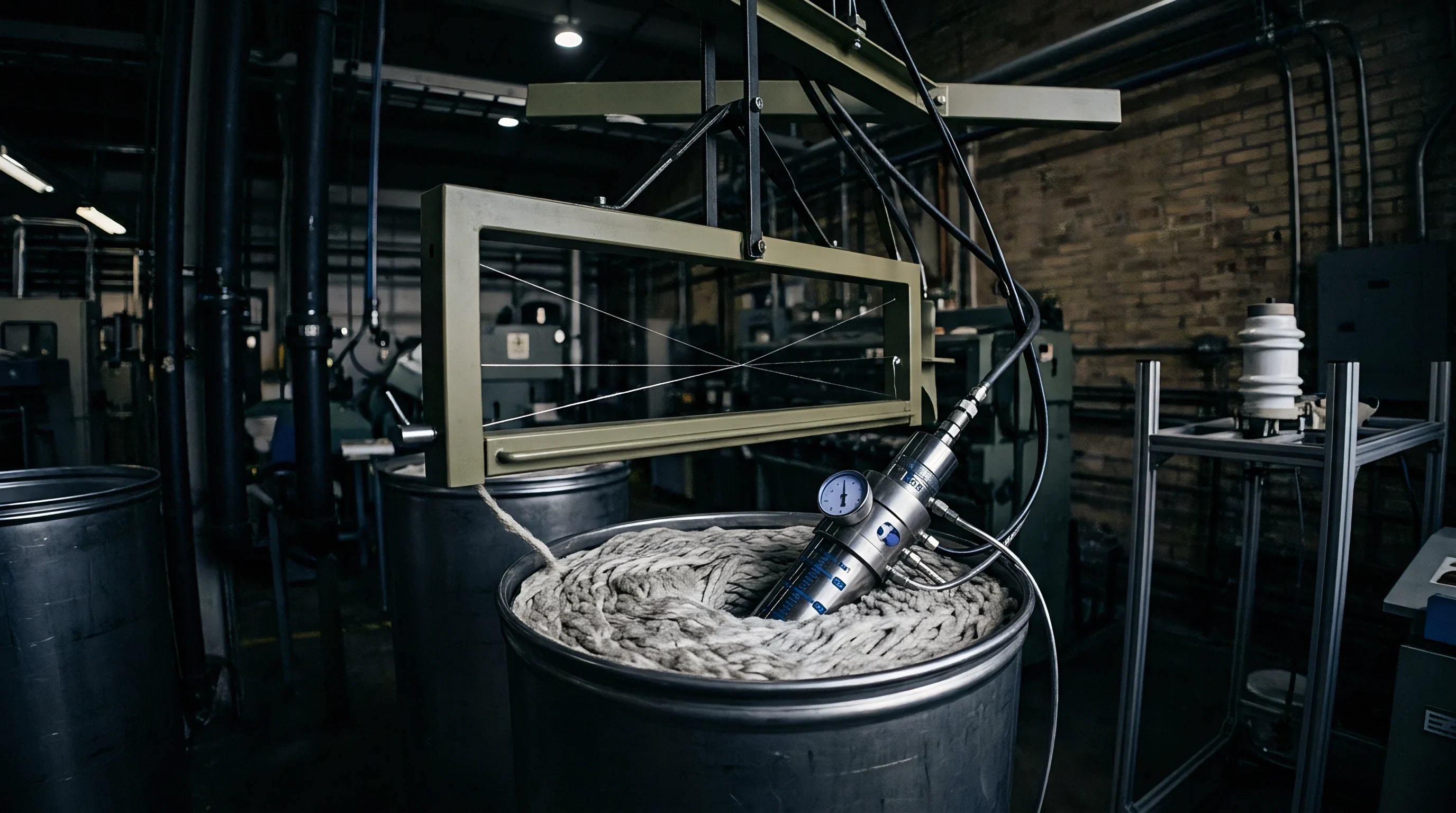

Stroke
In continuous dyeing runs, piston displacement mechanics control how much concentrate enters the pad trough. Positive displacement metering pumps push colorants and alkaline chemical feeds from storage tanks into a low-volume pad trough ~ typically holding between five and twenty litres ~ to prevent chemical degradation and shade instability over time. Maintaining a constant liquor level at exact chemical ratios requires volumetric delivery to match fabric consumption rates continuously.
When a padder runs fabric at eighty metres per minute with a wet pickup of sixty-five percent, the pump system feeds liquor at the precise rate fabric absorbs it. A failure in displacement calibration alters bath concentration within minutes, driving shade variations down the length of the fabric roll.
Reciprocating plunger and diaphragm metering pumps rely on precise linear travel to move fixed fluid volumes per cycle. Motor rotation converts to reciprocating linear motion through an eccentric drive and connecting rod mechanism. Adjusting the micrometer stroke alters the pivot position or limit stop, expanding or contracting the internal chamber volume swept by the plunger.
Calibration verifies that each mark on the micrometer scale reflects true volumetric displacement across the pump’s operating range. Over time, gear backlash, cam wear, and loose pin joints create mechanical hysteresis ~ meaning displacement generated when adjusting upward differs from the volume delivered when dialling down from a higher setting.

Positive Displacement Geometry and Mechanical Linkages
Plunger dosing assemblies turn rotational motor output into predictable linear fluid transfer. Theoretical output per stroke follows simple geometry: plunger cross-sectional area multiplied by total stroke length. Effective delivery rates, however, depend on motor speed, gear reduction ratios, and mechanical efficiency.
The sequence below details the physical calibration procedure required to zero and align the stroke mechanism on a dual-head piston dosing pump.
- Isolate the dosing pump from pressurized supply manifolds and relieve residual liquid line pressure through manual drain valves.
- Mount a dial indicator with zero point point five hundredth millimeter resolution against the rear face of the reciprocating plunger shaft.
- Rotate the drive motor shaft manually to locate bottom dead center and top dead center positions for the current micrometer setting.
- Adjust the mechanical micrometer scale to zero percent stroke and verify zero plunger movement across a complete drive cycle.
- Set the micrometer scale to twenty-five percent travel, measure true plunger displacement with the dial indicator, and record mechanical error.
- Repeat physical stroke measurements at fifty percent, seventy-five percent, and one hundred percent travel settings to verify mechanical linearity.
- Lock the micrometer positioning collar and torque set-screws to specified operational values before reconnecting fluid supply lines.
Tolerances inside drive linkages cause non-linear delivery at extreme stroke limits. Below fifteen percent stroke capacity, small clearances between the drive pin and connecting rod absorb a significant fraction of plunger motion, leaving actual displacement short of calculated output. Above ninety percent capacity, spring compression dynamics can cause stroke overshoot at high speeds.
Dosing pumps deliver maximum volumetric accuracy when operated between twenty and eighty percent of rated stroke capacity.
Stroke efficiency is calculated by comparing true displaced fluid volume against theoretical geometric displacement. Operating at ten percent stroke length produces a 3.4 percent volumetric deviation compared to fifty percent stroke length. This variance shifts colorant concentration enough to pull shade fastness results outside acceptable limits under ISO 105-J03 assessment protocols.
The stroke setting dictates the stability of the entire chemical delivery network.
Volumetric displacement linearity degrades beyond a three percent error margin when mechanical stroke settings drop below fifteen percent of total plunger travel.

Linearity Verification across Variable Displacement Range
Testing discharge volumes across five setting points highlights structural non-linearities in crank arm geometry. Technicians construct volumetric calibration curves by measuring water discharge into calibrated glass cylinders over controlled time intervals, using electric timers linked to motor rotation counters to capture an exact number of pump strokes. Plotting measured volume against micrometer readings establishes the true operational response of the dosing assembly.
Table 1 outlines empirical calibration data collected from a dual-piston volumetric dosing unit rated at ten litres per minute total capacity. The measurements illustrate how mechanical stroke adjustments translate to actual delivered fluid volume under controlled atmospheric pressure and ambient water temperature.
| Micrometer Setting (%) | Plunger Travel (mm) | Theoretical Rate (L/min) | Measured Rate (L/min) | Volumetric Error (%) | Tolerance Limit (%) |
|---|---|---|---|---|---|
| 10.0 | 4.00 | 1.000 | 0.945 | -5.50 | ±1.50 |
| 20.0 | 8.00 | 2.000 | 1.972 | -1.40 | ±1.50 |
| 40.0 | 16.00 | 4.000 | 3.980 | -0.50 | ±1.50 |
| 60.0 | 24.00 | 6.000 | 6.012 | +0.20 | ±1.50 |
| 80.0 | 32.00 | 8.000 | 8.008 | +0.10 | ±1.50 |
| 100.0 | 40.00 | 10.000 | 10.150 | +1.50 | ±1.50 |
The calibration curve generated from water testing forms the baseline for operational pump setting calculations. However, colorant solutions and chemical auxiliary mixes possess physical characteristics distinct from standard calibration fluids. Adjusting mechanical stroke length compensates for known linear errors, but non-linear mechanical wear demands physical component replacement or direct digital stroke profiling.
Dye houses that ignore low-stroke non-linearity suffer from uncalibrated low-flow dosing rates during narrow-width fabric production runs.
A simple rule of thumb holds that mechanical stroke adjustments ought to stay within the middle sixty percent of total micrometer travel to maintain volumetric precision.
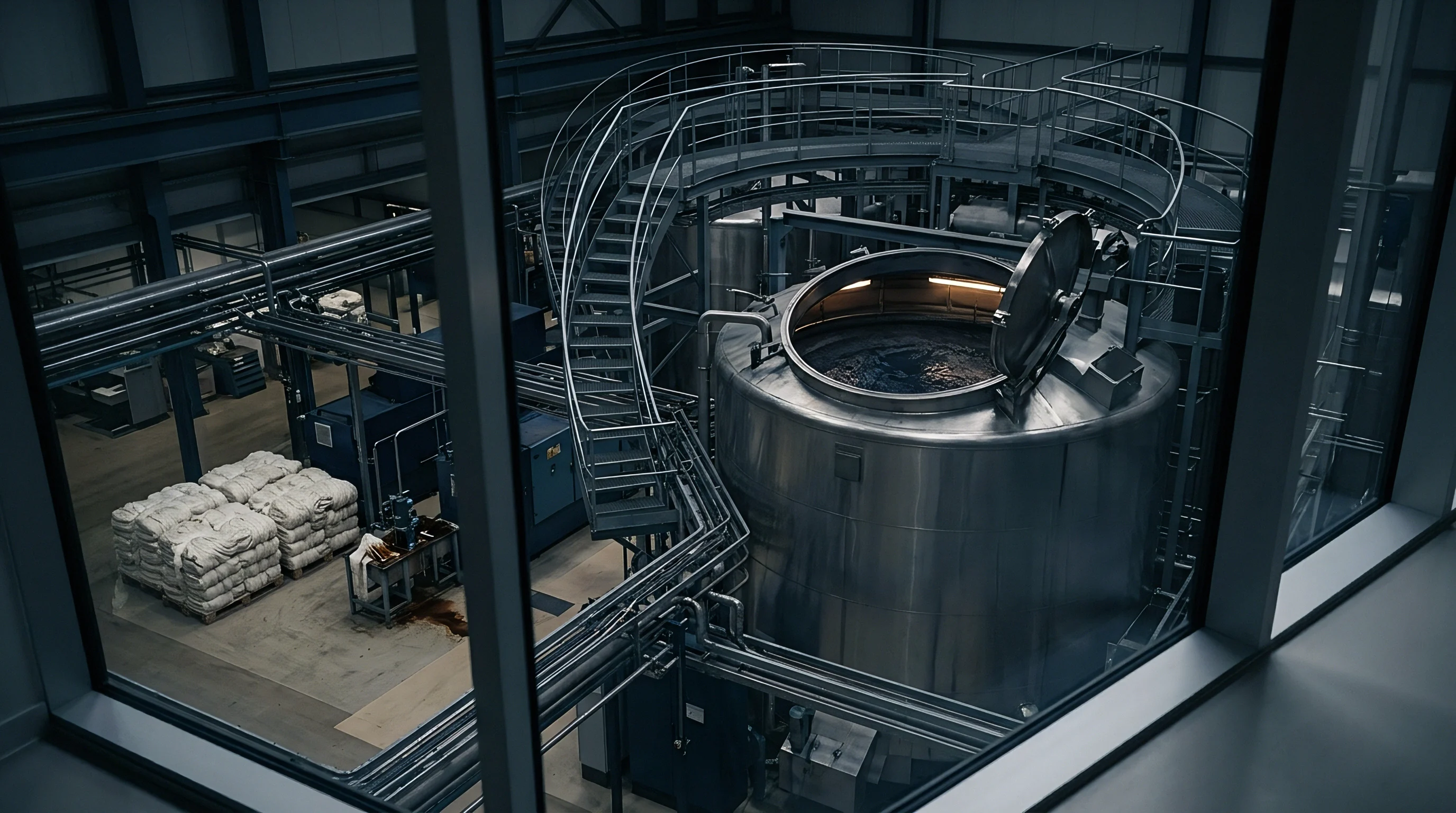

Manifold
Fluid distribution blocks combine separate chemical feeds immediately before entry into the liquor trough. In reactive pad-batch dyeing, alkalis like sodium hydroxide and sodium silicate react with dissolved dyes on contact. Premature mixing in bulk storage tanks causes dye hydrolysis within hours, destroying color yield and wet fastness.
The pad dyeing line uses a multi-channel manifold to blend dye concentrate, chemical auxiliaries, and fixatives fractions of a second before liquor enters the pad trough.
The volumetric ratio between dye solution and alkali solution must remain constant throughout the production lot. Typical cold pad-batch formulations demand a four-to-one volumetric dosing ratio, combining four parts of dye solution with one part of alkali fixative liquid. The dosing pump assembly uses coupled mechanical drive shafts or synchronized servo motors to drive separate dye and alkali pump heads simultaneously.
Calibration verifies both individual head displacement and the overall ratio maintained across varying motor speeds.

Check Valve Seating and Pressure Differential Balance
Spring-loaded ball valves prevent dye liquor from siphoning back into concentrate lines during stroke pauses. In positive displacement dosing systems, each pump head contains suction and discharge check valve assemblies. During the suction stroke, internal pressure drops, causing the inlet valve ball to lift from its seat while the outlet valve ball seals shut under manifold backpressure.
During the discharge stroke, pressurized liquid forces the outlet ball open, propelling fluid into the dosing manifold.
Check valve performance dictates volumetric dosing consistency under variable line pressures. Worn valve balls, pitted seating rings, or particulate accumulation prevent complete seal closure. Liquid back-flow occurs during stroke transitions, reducing true volumetric displacement per pump cycle.
If the dye pump check valve operates with a lower cracking pressure than the alkali check valve, dye concentrate flows preferentially into the manifold, altering the critical four-to-one chemical ratio.
The list below establishes verification parameters for manifold pressure stability and check valve integrity during wet processing operations.
- Cracking Pressure Verification tests spring force thresholds on inlet and outlet check valves to ensure simultaneous opening across all dosing channels.
- Seat Integrity Inspection detects micro-grooving and chemical pitting on ceramic or stainless steel seating surfaces using pneumatic pressure decay methods.
- Differential Pressure Balance maintains identical backpressure conditions across dye and alkali injection channels using spring-loaded inline pressure sustaining valves.
- Pulse Damping Efficiency absorbs pressure surges caused by reciprocating plungers, preventing dynamic pressure spikes from lifting check valve seats out of sequence.
- Manifold Cleanliness Protocol prevents cross-contamination and particulate buildup within injection nozzles through automated flush cycles between color changes.
Unmitigated pressure surges from reciprocating pistons create delivery errors. Installing hydropneumatic pulse dampeners downstream of dosing pump heads smooths pressure fluctuations, converting pulsating liquid flow into a steady volumetric stream. Pulsation damping prevents check valve chatter and ensures stable fluid velocity through static mixing elements located inside the dosing manifold assembly.
Contracts governing continuous pad dyeing lines mandate liquor dosing variances below one point five percent to prevent shade rejection under ISO 105-J03 color evaluation.

Dynamic Mixing and Ratio Control Mechanics
Cold pad-batch operations demand immediate homogeneous contact between reactive colorants and concentrated sodium hydroxide solutions. The dosing manifold incorporates internal motionless static mixers featuring helical or vane elements. Fluid streams entering the mixer undergo continuous division, radial displacement, and recombination.
The degree of mixing depends on fluid velocity, viscosity, and the number of mixing elements present within the manifold channel.
To illustrate the operational arithmetic of mechanical volumetric dosing calibration, consider a continuous pad dyeing line processing cotton fabric. The operational parameters for this worked example are established below:
- Fabric Specification: 100% Cotton Woven Twill, 220 g/m² finished weight, 1.60 metres usable width.
- Production Speed: 60 metres per minute continuous line speed.
- Target Wet Pickup: 65.0% (0.65 kg dye liquor per kg dry fabric).
- Dosing Ratio: 4 : 1 volumetric ratio (4 parts Dye Concentrate Solution to 1 part Alkali Solution).
- Dye Concentrate Density: 1.040 kg/L at 20°C.
- Alkali Solution Density: 1.220 kg/L at 20°C.
First, calculate the total dry mass of fabric passing through the padder per unit time. Fabric mass rate equals speed multiplied by fabric width and mass per unit area. Converting parameters yields sixty metres per minute times one point six metres width times zero point two two kilograms per square metre, resulting in twenty-one point one two kilograms of dry fabric per minute.
Second, determine the required total liquid pickup mass flow rate. Total liquid mass rate equals dry fabric mass rate multiplied by target pickup percentage. Multiplying twenty-one point one two kilograms per minute by zero point six five yields thirteen point seven two8 kilograms of total mixed dye liquor per minute.
Third, convert total mass flow rate into total volumetric flow rate based on combined mixed bath density. The weighted density of a four-to-one volumetric mixture equals zero point eight times dye density plus zero point two times alkali density. Calculating yields zero point eight times one point zero four zero plus zero point two times one point two two zero, resulting in one point zero seven six kilograms per litre.
Fourth, calculate total volumetric delivery rate required from the dosing manifold. Total volume rate equals total liquid mass rate divided by mixed bath density. Dividing thirteen point seven two eight kilograms per minute by one point zero seven six kilograms per litre yields twelve point seven five eight litres of mixed liquor per minute.
Fifth, split total volumetric flow into individual pump delivery rates based on the four-to-one ratio split. The dye pump must deliver four-fifths of total volume while the alkali pump delivers one-fifth. Dye volume rate equals twelve point seven five eight times zero point eight, resulting in ten point two zero six litres per minute.
Alkali volume rate equals twelve point seven five eight times zero point two, resulting in two point five five two litres per minute.
If check valve slippage cuts the alkali pump’s volumetric efficiency by five percent, actual alkali flow drops to two point four two four litres per minute. The effective dosing ratio shifts from four to one up to four point two one to one. Lower alkali fixative concentration decreases fixation yield on vinyl sulfone reactive dyes, causing severe tailing and leaving the end of the roll off-shade compared to the lab dip.
Dynamic inline mixers do not eliminate the need for mechanical ratio calibration by compensating for pressure drops, as static mixing elements cannot generate missing liquid volume or correct broken pump stroke ratios.


Viscosity
Concentrated dye baths carry internal shear resistance that alters volumetric delivery as flow velocity changes. Aqueous solutions containing dissolved reactive, disperse, or acid colorants behave differently than clean water. Adding anti-migration agents, wetting surfactants, thickeners, and salts increases internal fluid friction.
In mechanical displacement pumps, higher fluid viscosity retards liquid entry through suction valve seats, causing incomplete cylinder filling during fast stroke cycles.
Volumetric efficiency measures actual fluid volume delivered per stroke against maximum theoretical cylinder volume. When pumping viscous dye concentrates, suction line flow resistance generates partial vacuum conditions inside the displacement chamber. Dissolved air escapes from solution, forming small vapor pockets through cavitation.
The plunger compresses these air pockets during the initial portion of its discharge stroke before building enough hydraulic pressure to unseat the outlet check valve, dropping volumetric discharge significantly below geometric calculations.

Shear Rate Effects on Volumetric Efficiency
High-concentration alginate thickeners and acrylic levelling agents exhibit non-Newtonian behavior under pressure. These pseudoplastic fluids display shear-thinning characteristics where internal viscosity decreases as applied shear rate rises. Inside the tight clearances of pump plungers, valve orifices, and dosing manifolds, shear rates exceed ten thousand reciprocal seconds.
Fluid viscosity drops rapidly within the pump head during high-speed strokes, then recovers original thickness once the fluid enters the low-shear environment of the pad trough.
Mechanical volumetric calibration protocols must utilize operational fluids or viscosity-matched reference liquids rather than plain water. Calibrating a dosing pump with water yields a volumetric delivery curve that overestimates chemical delivery when switching to thick dye concentrates. As fluid viscosity increases from one centipoise to fifty centipoise, pump slip factors change due to modified laminar flow profiles across internal valve clearances.
Table 2 demonstrates how dye bath viscosity alters volumetric metering pump performance across identical mechanical stroke settings. The test data reflects a single-head plunger pump operating at sixty strokes per minute at twenty degrees Celsius ambient temperature.
| Viscosity (mPa·s) | Fluid Character | Target Flow (L/min) | Actual Flow (L/min) | Efficiency Loss (%) | Suction Head Loss (bar) |
|---|---|---|---|---|---|
| 1.0 | Newtonian (Water) | 5.000 | 4.975 | 0.50 | 0.05 |
| 10.0 | Low Polymer Mix | 5.000 | 4.890 | 2.20 | 0.12 |
| 25.0 | Medium Reactive Mix | 5.000 | 4.750 | 5.00 | 0.28 |
| 50.0 | Heavy Alginate Mix | 5.000 | 4.510 | 9.80 | 0.55 |
| 100.0 | High Viscosity Concentrate | 5.000 | 4.120 | 17.60 | 0.92 |
Suction head loss increases dramatically as fluid viscosity rises. When suction head loss approaches the net positive suction head limit of the pump, cylinder filling starves completely. To maintain volumetric dosing accuracy when handling high-viscosity dye formulations, operators must reduce pump stroke frequency, increase suction pipe internal diameters, or pressurize supply tank head spaces.
Higher dye bath shear resistance increases internal pump slip and reduces true liquid discharge volume below calibrated micrometer expectations.

Temperature Dependent Liquid Density Variations
Thermal shifts in the chemical preparation room alter both fluid volume and internal mechanical clearances. Chemical preparation tanks stored in non-conditioned dyehouse environments undergo temperature fluctuations between fifteen degrees Celsius during winter morning shifts and forty degrees Celsius during hot summer afternoons. Liquid volume expands as temperature rises, reducing mass concentration per unit volume.
Pump displacement remains mechanically volumetric, but the actual mass of colorant delivered per pump stroke drops at elevated temperatures.
Volumetric pump components experience thermal expansion when handling warm dye liquors. Stainless steel plungers and ceramic sleeves expand at different rates depending on their thermal expansion coefficients. Tighter mechanical clearances at higher temperatures increase sliding friction and accelerate seal wear.
Oversized clearances at lower temperatures increase internal fluid bypass around piston rings, lowering volumetric efficiency during startup phases.
Uncompensated thermal shifts of fifteen degrees Celsius cause density-driven color yield errors exceeding two point eight percent in concentrated reactive dye solutions. This shift alters color fastness and shade match reproducibility across multi-shift production runs.
Automated dosing control networks must compensate for non-linear viscosity drops and thermal volume expansion to prevent constant manual gravimetric recalibration.


Gravimetry
Mass-based liquid calibration overrides volumetric sight-glass estimates by isolating environmental thermal expansion. While volumetric sight glasses and graduated cylinders provide visual verification, they introduce measurement uncertainties due to meniscus reading errors, foam accumulation, and temperature-dependent container volume shifts. Gravimetric verification measures the actual mass of liquid delivered by a dosing system over a precise time window using high-precision digital balances linked to electronic timers.
Converting measured liquid mass to true volumetric delivery requires accurate fluid density determination at the precise calibration temperature. Fluid density is measured using digital density meters operating on the oscillating U-tube principle or calibrated glass pycnometers according to standard laboratory methods. Dividing the measured mass by liquid density yields the absolute volumetric flow rate delivered by the dosing mechanism under operational backpressure conditions.

Do Temperature Changes Disrupt Volumetric Calibration Balances?
Fluid density decreases linearly as ambient mixing tank temperatures rise during multi-shift dyeing operations. Volumetric calibration relies on stable density parameters to calculate chemical mass delivery rates. If a calibration procedure takes place at eighteen degrees Celsius but the operational dye liquor runs at thirty-five degrees Celsius, mass delivery calculations introduce systematic error.
Table 3 outlines temperature-density relationships for common textile pad dyeing chemical concentrates used in gravimetric calibration calculations.
| Chemical Solution | Nominal Conc. (g/L) | Density at 15°C (g/cm³) | Density at 25°C (g/cm³) | Density at 35°C (g/cm³) | Expansion Coeff. (1/°C) |
|---|---|---|---|---|---|
| Water (Reference) | – | 0.9991 | 0.9970 | 0.9940 | 0.00021 |
| Reactive Dye Stock | 80.0 | 1.0380 | 1.0345 | 1.0305 | 0.00036 |
| Sodium Hydroxide (38°Bé) | 325.0 | 1.3550 | 1.3495 | 1.3435 | 0.00043 |
| Sodium Silicate (38°Bé) | 380.0 | 1.3700 | 1.3640 | 1.3575 | 0.00046 |
| Urea Stock Solution | 200.0 | 1.0520 | 1.0475 | 1.0425 | 0.00045 |
Gravimetric calibration protocols apply thermal correction factors to convert recorded mass values back to standardized reference volumes at twenty degrees Celsius. Neglecting thermal expansion coefficients when calibrating dense alkali feeds creates discrepancy between intended chemical additions and actual mass fixed to the fabric substrate.

Gravimetric Procedure for High-Speed Dosing Pumps
Collecting discharged liquor into tared stainless vessel assemblies over fixed time intervals establishes true mass delivery rates. The calibration rig incorporates three-way diverter valves positioned immediately upstream of the pad trough injection point. Actuating the diverter valve redirects fluid flow into the collection vessel without interrupting pump operation or altering manifold backpressure conditions.
The operational failure modes listed below compromise gravimetric dosing accuracy and require routine diagnostic screening during maintenance audits.
- Entrained Air Bubbles lower effective liquid density, causing gravimetric measurements to record lower mass delivery than visual sight-glass volume readings suggest.
- Evaporative Mass Loss reduces recorded fluid weight during prolonged collection intervals when testing high-temperature chemical stock solutions.
- Diverter Valve Travel Hysteresis introduces timing variations between valve opening and closing, skewing short-duration mass collection samples.
- Scale Signal Drift caused by mechanical vibration from adjacent stenter frames or padder drives ruins balance resolution and repeatability.
- Backpressure Deviation between the collection vessel line and the active dosing manifold alters pump slip, making calibration data unrepresentative.
Gravimetric verification establishes the absolute accuracy of mechanical dosing systems under controlled conditions. Calibration protocols require balances calibrated to ISO 17025 standards with a minimum resolution of zero point zero one grams for small-volume pumps and zero point one grams for primary liquor dosing lines. Gravimetric validation eliminates visual estimation errors and ensures strict compliance with technical fabric specifications.
Under standard commercial finishing contracts, fabric lots dyed on systems lacking documented gravimetric calibration receipts are subject to immediate shade dispute arbitration and full batch rejection rights if color variance exceeds Delta E zero point eight relative to approved standards.


Drift
Mechanical wear across elastomeric seals and ceramic plungers progressively reduces liquid delivery accuracy over run hours. Continuous friction between reciprocating plungers and stationary shaft packing seals causes microscopic material loss. As seal lips wear, internal high-pressure fluid leaks back into low-pressure suction chambers during each discharge stroke.
This internal bypass reduces volumetric discharge without exhibiting external fluid leaks on the dyehouse floor.
Dosing drift develops gradually over hundreds of operating hours. Plungers exposed to abrasive pigment dispersions or crystallized chemical salts develop axial scratches along their sealing surfaces. Scratch channels provide continuous bypass pathways for liquid slip.
Check valve balls lose their spherical geometry due to repeated impacts against valve seats, creating inconsistent seating angles and variable back-flow volumes.

Seal Erosion and Volumetric Loss Mitigation
Abrasive particulate matter in pigment dispersions scoring pump walls creates internal recirculation paths. Chemical exposure causes seal materials to swell or harden over time. Fluoroelastomer seals exposed to highly alkaline sodium hydroxide solutions undergo slow chemical embrittlement, losing elasticity needed to maintain lip pressure against reciprocating plungers.
Mechanical wear and chemical degradation combine to lower volumetric efficiency at a rate of zero point five to two percent per thousand operating hours.
Preventative maintenance schedules demand systematic replacement of seals, O-rings, and check valve components based on total stroke counts rather than calendar time. Digital stroke counters installed on pump drive shafts trigger maintenance warnings when cumulative cycles reach seal supplier operational limits. Replacing wear components before volumetric degradation occurs prevents uncalibrated dosing shifts during production runs.
Dosing drift alters color yield across long production lots, producing head-to-tail shade variation. When dosing efficiency decays over a ten-thousand-metre dyeing run, the initial fabric metres receive correct chemical concentrations while final metres suffer from reduced color strength or incomplete fixative ratios.

Closed Loop Feedback and Inline Mass Flow Interlocking
Coriolis meters installed downstream of mechanical dosing units provide real-time pulse corrections to drive motors. Coriolis mass flow meters measure mass flow rate, fluid density, and fluid temperature directly without relying on volumetric assumptions. Integrating Coriolis meters into dosing lines creates a closed-loop control system that monitors physical mass delivery against target setpoints calculated by the central padder control unit.
When mechanical drift occurs in the pump head, the inline Coriolis meter detects the mass flow deficit immediately. The system controller calculates the error margin and increases motor speed or advances the mechanical micrometer stroke setting via an automated servo actuator. Closed-loop feedback compensates for mechanical wear, seal erosion, viscosity shifts, and thermal density variations in real time, maintaining liquor ratio stability across extended production runs.
Uncorrected mechanical drift in dosing pumps alters dye-to-alkali ratios and causes continuous shade variation across long fabric production rolls.
Ignoring mechanical dosing calibration leads to uncompensated volumetric decay, resulting in off-shade fabric rolls, ruined lot yields, severe commercial penalties, and complete loss of buyer account qualification status.