Refractive Index Perturbations in High Speed Optoelectronic Polymer Sorting Chute Air Boundaries
Boundary layer air density variations refract optoelectronic sensing beams in high-speed sorting chutes, degrading polymer identification and yield.

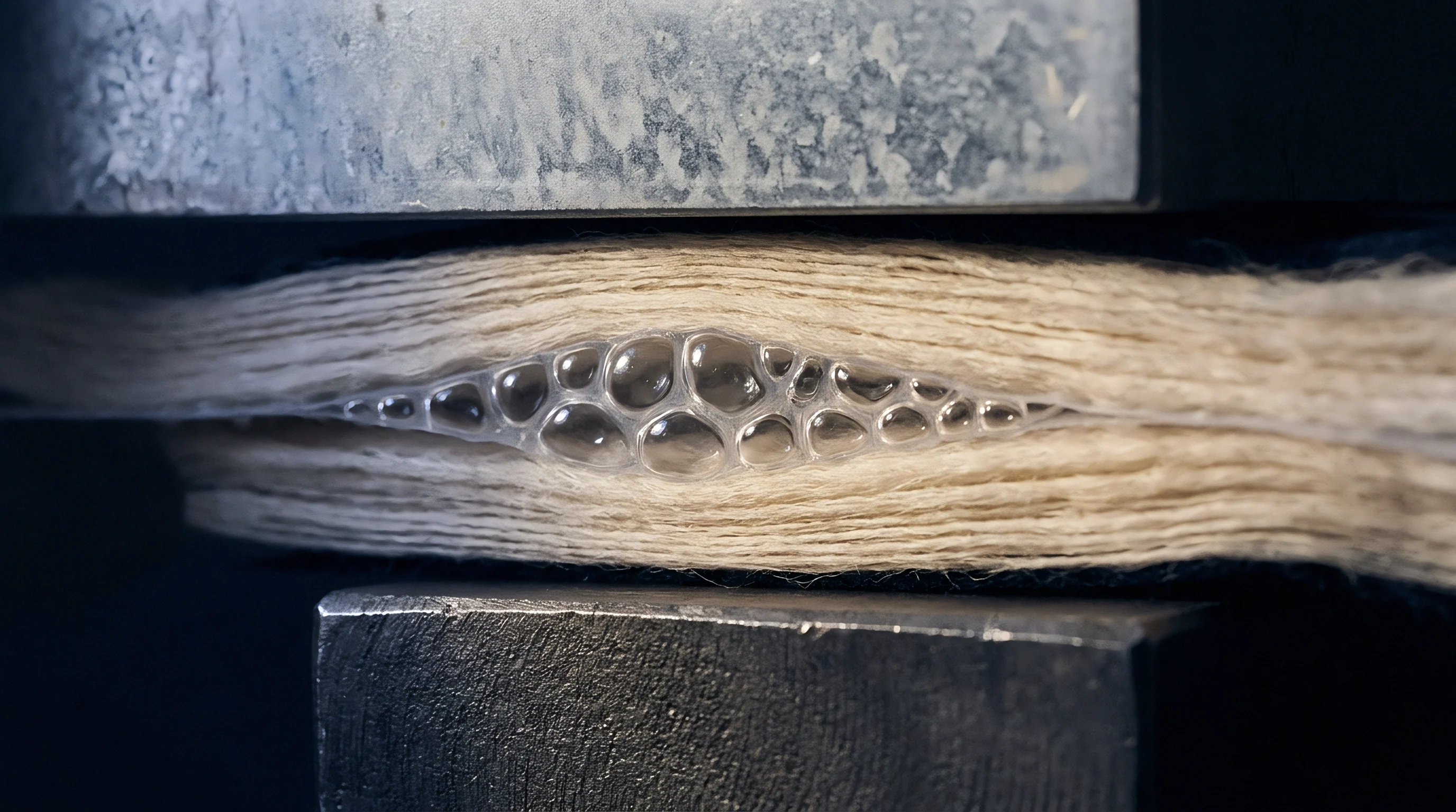
Shear
A three-millimetre thick turbulent air boundary layer on an inclined polymer sorting chute alters local gas density by four percent under focused high-intensity infrared illumination. High-speed optoelectronic sorting platforms move granulated polymer flakes, shredded textile staple, and recycled resin pellets down inclined metal chutes at linear velocities ranging from 3.0 to 5.5 metres per second. Air density dictates optical refraction.
Moving polymer streams entrain adjacent air through shear forces, generating micro-vortices alongside stationary chute sidewalls. Localized air compression and velocity differentials create spatial density variations within the optical measurement path.
The Gladstone-Dale relation governs the relationship between local air density and its refractive index. Air density variations directly shift the refractive index according to the equation:
n – 1 = K ρ
where n represents the refractive index, K defines the Gladstone-Dale constant for air at 0.226 cubic centimetres per gram, and ρ is the local gas density in grams per cubic centimetre. When chute air speed fluctuates, compressed air packets generate instantaneous refractive index differentials up to 1.5 10-5. Light rays crossing these density gradients experience spatial bending and phase delay.
High-speed optoelectronic detectors rely on sub-millimetre optical spatial precision to categorize polymer types. Uncontrolled boundary layer shear displaces focused light across the photodiode array, destabilizing spectral measurements.
Air boundary compression at 5.0 metres per second creates a refractive index differential of 0.000015 across a ten-millimetre optical sensing height.
Optical signal degradation stems from distinct aerodynamic mechanisms acting inside the boundary region:
- Boundary Layer Thickening friction along the chute bed decelerates air relative to the fast-moving polymer stream, expanding the turbulent boundary zone into the optical path.
- Velocity Vortex Shedding periodic air shear detachment at chute joints generates roving high-density pockets that refract optical beams away from sensor elements.
- Sidewall Drag Shear boundary drag near enclosure walls creates lateral refractive gradients that skew spatial optical alignment across outer sensing channels.
- Pressure Drop Micro-Plumes localized low-pressure zones behind tumbling polymer particles warp passing illumination light before rays reflect back into the spectrometer lens.
Whether adaptive wavefront sensing can dynamically correct air boundary distortions before rays reach the photodiode array remains an unproven approach in continuous high-tonnage reclaim operations.


Gradient
Friction generates localized air heating along the chute bed during continuous sorting. Thermal energy from high-power illumination sources transfers into the chute structure and adjacent boundary air. Near-infrared and short-wave infrared optical sorting systems deploy illuminator arrays producing optical power densities exceeding 120 watts per square metre.
Continuous optical energy absorption warms the chute bed surface, raising boundary air temperatures 15 to 35 degrees Celsius above ambient hall levels.

Why Do Thermal Air Boundaries Shift Optoelectronic Spectrum Peaks?
Illumination intensity drives air expansion. Thermal gradients decrease local air density as temperature rises according to the ideal gas law. A ten-degree Celsius rise in boundary air temperature lowers the refractive index of air by approximately 1.0 10-6.
Thermal plumes create optical lenses in the sensing zone. Ray paths passing through heated air boundaries suffer optical defocusing and spatial aberration. Refractive shifts distort spectral signatures, altering observed absorption peak positions for polymers such as Polyethylene Terephthalate, Polyamide 6, and Polypropylene.
The table below summarizes observed optoelectronic signal anomalies across thermal boundary gradients in high-speed sorting chutes.
| Polymer Type | Boundary Temp Delta (°C) | Refractive Index Shift (Δn) | Wavelength Offset (nm) | Identification Error Rate (%) |
|---|---|---|---|---|
| Polyethylene Terephthalate (PET) | +10 | -0.0000010 | 0.4 | 0.8 |
| Polyethylene Terephthalate (PET) | +25 | -0.0000025 | 1.2 | 3.4 |
| Polyamide 6 (PA6) | +10 | -0.0000010 | 0.5 | 1.1 |
| Polyamide 6 (PA6) | +25 | -0.0000025 | 1.5 | 4.2 |
| Polypropylene (PP) | +10 | -0.0000010 | 0.3 | 0.6 |
| Polypropylene (PP) | +25 | -0.0000025 | 1.0 | 2.9 |
Density gradients warp light paths. When illuminated light rays traverse thermal boundaries at oblique angles, non-uniform refractive indices curve the light propagation trajectory. Ray path deviation causes misclassification by shifting the focused optical spot off the designated line-scan sensor channel.
Cooling air introduced into an optoelectronic chute performs best when supplied at the exact velocity of the polymer flake stream.
Engineering teams select sorting enclosure mitigation steps through systematic technical evaluations:
- Conductive Chute Cooling integrated liquid cooling channels beneath the chute bed absorb excess illuminator energy to suppress thermal boundary development.
- Laminar Air Injection thin non-turbulent air streams blown across the optical window flush thermal plumes out of the illumination path.
- Spectral Band Shift Compensation calibration software modifies classification baseline thresholds to accommodate predictable thermal refractive drift.
Cooling air introduced into an optoelectronic chute works best when fed at the exact velocity of the flake stream.

Deflection
Snell’s law governs optical light bending at air boundary interfaces exhibiting density step-changes. Light rays exiting the uniform ambient air environment and entering a turbulent boundary layer shift direction based on local refractive indices:
n1 sin(θ1) = n2 sin(θ2)
where n1 and n2 represent refractive indices of ambient and boundary air, while θ1 and θ2 define optical angles of incidence and refraction. Accumulating angular deviations over a 300-millimetre sensor focal distance translates micro-refractions into measurable spatial positioning errors on detector planes.
Spatial ray deflection broadens the point spread function of the optics setup. Blurred optical spots bleed light onto adjacent detector pixels, blending spectral readings from neighbouring polymer flakes or chute background tiles. Misallocated flakes reduce lot purity.
Cross-pixel optical contamination reduces signal-to-noise ratios, degrading polymer identification algorithms during high-speed sorting operations.
| Air Boundary Velocity (m/s) | Boundary Layer Thickness (mm) | Calculated Angular Deflection (μrad) | Spatial Spot Shift at Sensor (μm) | Signal-to-Noise Loss (dB) |
|---|---|---|---|---|
| 3.0 | 4.5 | 12.0 | 3.6 | 0.4 |
| 4.0 | 7.2 | 28.5 | 8.55 | 1.2 |
| 5.0 | 10.5 | 52.0 | 15.6 | 2.8 |
| 6.0 | 14.0 | 88.0 | 26.4 | 5.1 |
| Test conditions: Focal distance 300 mm, light wavelength 1450 nm, ambient air temp 20 °C, illumination optical power 100 W/m2. | ||||
Sorting accuracy hinges on maintaining exact spatial synchronization between optoelectronic detection and downstream pneumatic ejection valves. Optical beam bending alters the perceived physical position of target particles on the chute bed. Pneumatic rejection nozzles fire based on calculated timing arrays tied to optical particle detection coordinates.
Standard ISO 1833 delivery protocols mandate that optoelectronic polymer sorting lines hold flake identity misclassification below zero point five percent by weight.
Deflected light paths register particles several millimetres away from their true spatial locations. Air nozzles mistime their compressed air pulses, missing target contaminant flakes entirely or striking adjacent compliant polymer particles. Uncorrected optical ray bending causes misdirected pneumatic air ejection pulses that blow correct target flakes into the reject bin, driving product loss up to four percent by weight.

Calibration
High-speed optoelectronic sorting equipment requires dynamic calibration routines to counteract changing boundary layer conditions. Environmental fluctuations inside recycling plants alter ambient air density, humidity, and temperature throughout operating shifts. Air speed determines boundary layer thickness.
Automatic compensation routines stabilize optical baseline readings against progressive boundary air heating and turbulence build-up.
Pneumatic curtains stabilize local density. Operating teams execute standardized procedures to baseline optoelectronic chute boundaries during sorting system commissioning:
- Purge chute optical enclosures using compressed dry air to clear dust particles and establish uniform baseline pressure.
- Energize infrared illuminator arrays at full operating power for twenty minutes to achieve thermal equilibrium across the chute structure.
- Measure boundary air velocity profiles at five points across the chute width using thermal anemometers.
- Adjust laminar air curtain blowers until velocity variances across the optical sensing plane fall below two percent.
- Acquire dark-current and white-reference optical calibration scans using certified ceramic background tiles.
- Map spatial beam spot locations on the sensor array to record optical deflection baselines under active air curtain flow.
- Program differential algorithm gains across individual line-scan channels to equalize optical signal amplitudes across the chute width.
Sensors demand precise optical alignment. Dynamic gain control algorithms continuously sample empty chute background spectrums between passing polymer flakes. Algorithms compute real-time optical baseline shifts caused by turbulent air boundary fluctuations and recalibrate pixel sensitivities dynamically.
Laminar air flow velocity matching the main polymer flake trajectory eliminates boundary air shear micro-vortices across the optical sensing line.
Sorting equipment manufacturers frequently attribute persistent polymer misclassification to raw material flake contamination rather than admitting boundary layer air refractions degrade sensor accuracy.

Discrepancy
Purity drops trigger tariff penalties. Inaccurate polymer identification caused by optical boundary layer perturbations directly impacts the landed cost and commercial classification of bulk recycled materials. Recycled polymer shipments cross international borders under specific Harmonized System tariff codes linked directly to material purity percentages.
HS Code 3907.61 governs Polyethylene Terephthalate containing strict purity levels, whereas mixed polymer waste falls under HS Code 3915.90, carrying higher import duty rates and stringent environmental import restrictions.
Reclaim value depends on sorting accuracy. Commercial contracts for recycled Polyamide or PET flakes specify maximum acceptable contamination thresholds, typically capping foreign polymer inclusions at 0.5 percent by weight. When optoelectronic sorting chutes misclassify Polyamide 66 as PET due to boundary air refractions, non-conforming polymer enters the final product stream.
Downstream fiber extrusion mills purchasing these contaminated flake lots experience melt filter clogging, filament breakage, and dye bath streak defects during yarn manufacturing operations.
Secondary re-sorting processes impose direct financial burdens on recycling operations. Mills rejecting non-conforming bales pass re-testing costs, freight penalties, and lot downgrades back to the raw material supplier. Processing plants running high-speed optoelectronic sorters must factor boundary layer refractive perturbations into overall equipment efficiency calculations.
Failing to manage chute air boundary dynamics increases secondary re-sort frequency, elevates pneumatic energy consumption per processed tonne, and risks catastrophic customs misdeclaration claims on bulk international shipments.