Air Jet Loom Beat up Force Variance under High Warp Cover Factor Conditions
High warp cover factors drastically spike air jet loom beat-up forces, requiring optimized size films and asymmetric shed timing to prevent stop marks and yarn damage.

Resistance

Mechanics of Fell Movement in Dense Weaves
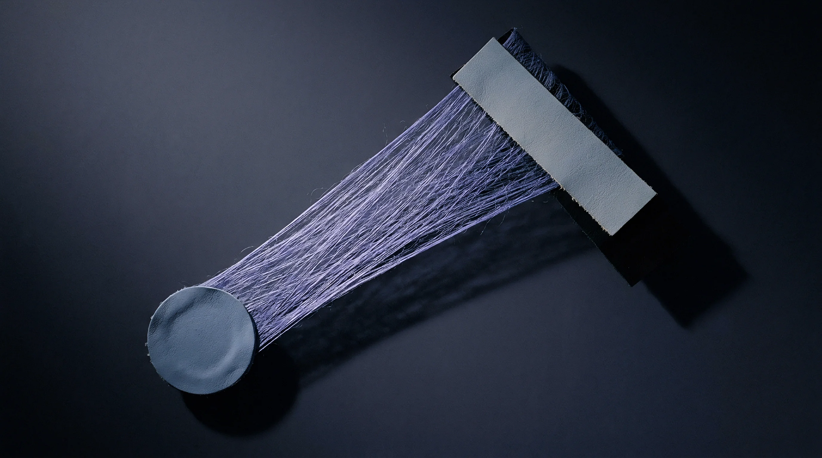
Fabric construction parameters dictate the mechanical load on the reed during final pick insertion. When the warp cover factor exceeds 18 under the standard Cotton System equation ~ where warp cover factor equals warp ends per inch divided by the square root of the English cotton yarn count ~ the physical space for each thread drops below what is needed for clear lateral movement. Forcing a weft thread into an overcrowded shed resists reed movement.
Instead of staying put, the cloth fell shifts forward during beat-up with greater displacement amplitude. The reed strikes a moving wall of yarn instead of an elastic boundary, so peak impact loads scale exponentially as end density increases.
Fell displacement during reed contact changes the geometry of the beat-up point. In loose weaves with warp cover factors under 14, the fell remains close to its static equilibrium position, so the reed pushes the pick into place with little energy loss. Higher cover density wedges adjacent warp yarns together, raising inter-yarn friction.
The reed drives the pick against a fell that gives way on impact, then snaps back as the reed recedes. This oscillation converts kinetic energy into sharp tension spikes across the warp sheet. On air jet machines, where yarn travels continuously through profiled reeds, fell movement disrupts the air channel geometry and throws off insertion timing.
How warp yarns deform also shifts at high density. Continuous filament yarns flatten laterally under reed impact, spreading out to absorb beat-up force. Ring-spun staple yarns lack that compliance; they resist compression and send energy straight back into the beat-up mechanism.
Compact spun yarns have excellent hairiness profiles, but their rigid outer sheath increases peak impact force by up to 35 percent compared to standard ring-spun yarns of the same linear density. Without surface cushioning, the drive motor must supply higher torque to finish the crank cycle, driving up power draw and straining the reed support arms.
Warp cover factors exceeding 19.5 increase peak beat-up force from 2800 N/m to over 6200 N/m on profile reeds running at 850 picks per minute.
Inter-Yarn Friction Kinetics at the Beat-Up Point
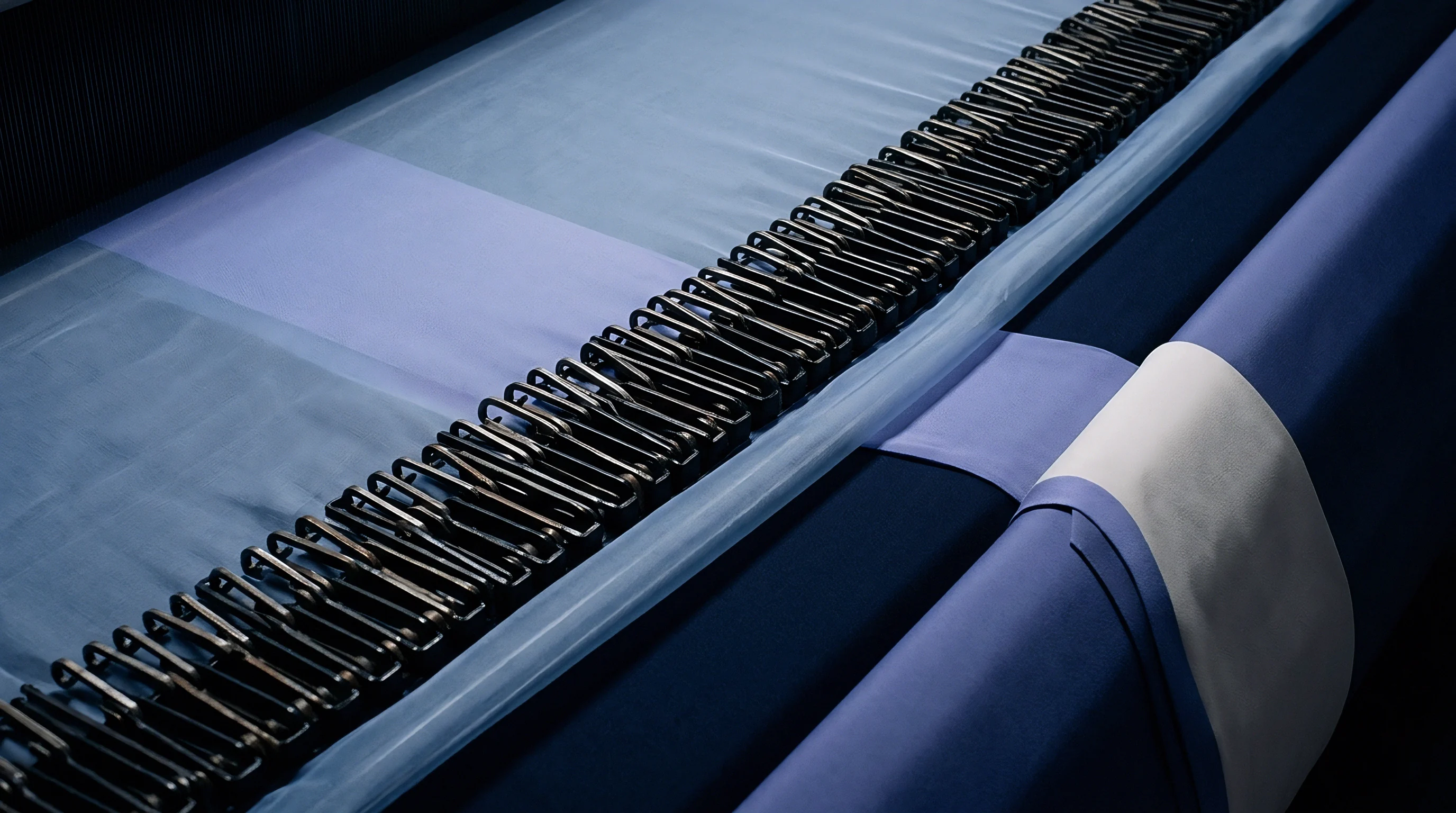
Friction between adjacent warp ends dominates resistance during reed contact. Approaching front dead centre, top and bottom warp lines cross while pressed against the fresh pick. Normal force between threads scales directly with shed angle and total warp tension.
High cover factors amplify this force because threads touch continuously along their length. The resistance to fell consolidation is simply the yarn-to-yarn friction coefficient multiplied by this heightened normal force.
Lubrication determines the kinetic friction coefficient during high-speed impact. Dry spun yarns without enough wax or size show friction coefficients above 0.35, creating beat-up resistance severe enough to trigger loom stops. Formulations with modified starches and synthetic wax lower the coefficient below 0.22, cutting peak beat-up loads by several hundred Newtons per metre.
Soft size films break down under repeated strikes, leaving sticky deposits on reed wires that double frictional drag over an eight-hour shift. Sizing chemistry has to balance slipperiness and film toughness to keep beat-up mechanics stable across long runs.
Setting pick density near maximum theoretical limit compounds friction further. The structural packing ceiling is reached as the combined warp and weft cover factors approach geometric jamming. At 92 percent of theoretical jamming, seating each pick requires aggressive compaction.
The reed stops acting as a positioning guide and beats the pick into the warp matrix like a hammer, generating force spikes that vibrate through the main frame and sley drive linkage.
| Warp Cover Factor | Pick Density (picks/cm) | Beat-Up Peak Force (N/m) | Fell Displacement (mm) | Air Pressure Drop (bar) |
|---|---|---|---|---|
| 14.5 | 24.0 | 1850 | 0.8 | 0.12 |
| 16.5 | 28.5 | 2600 | 1.4 | 0.18 |
| 18.5 | 32.0 | 4100 | 2.6 | 0.31 |
| 20.2 | 36.5 | 6450 | 4.2 | 0.52 |
| 21.8 | 40.0 | 8900 | 6.1 | 0.78 |

Structural Jamming Boundaries in High-Density Weaves
Geometric constraints set hard limits on beat-up feasibility on air jet machines. In plain weaves, crimp redistribution determines how picks nest in the warp matrix. As the reed pushes a pick forward, warp threads must bend around it while the pick bends around the warp.
High warp cover factors restrict thread movement, forcing the weft yarn to take on most of the crimp. If the weft yarn is too stiff to conform, structural jamming occurs before the pick reaches its target position.
Weave architecture controls crimp capacity and absorbs beat-up energy. Twill and satin structures have fewer warp and weft interlacing points than plain weaves, lowering total friction per unit length. A 3/1 twill shows 40 percent less beat-up resistance than a 1/1 plain weave with identical yarn count and sett parameters.
Sourcing teams specifying dense fabrics must factor in weave structure when assessing loom feasibility. Running high warp cover plain fabrics on standard air jet setups frequently causes reed marks, pick density variations, and main motor overloads.
Let-off warp tension settings also influence jamming resistance. Raising the back-rest roller widens the tension gap between top and bottom shed lines at the crossing, easing fell closure. This asymmetric geometry forces warp threads to pass each other sequentially rather than all at once, spreading the peak beat-up load over a broader crank angle.
Lowering overall off-loom warp tension lets the fell yield too much, increasing fell displacement and causing noticeable pick spacing variance down the roll.
Ignoring structural jamming boundaries leads directly to off-spec fabric density, elevated stop rates, and premature reed failure that raises finished fabric costs by more than 0.45 EUR per metre.

Peak

Kinematics of Reed Impact and Eccentric Drive Load
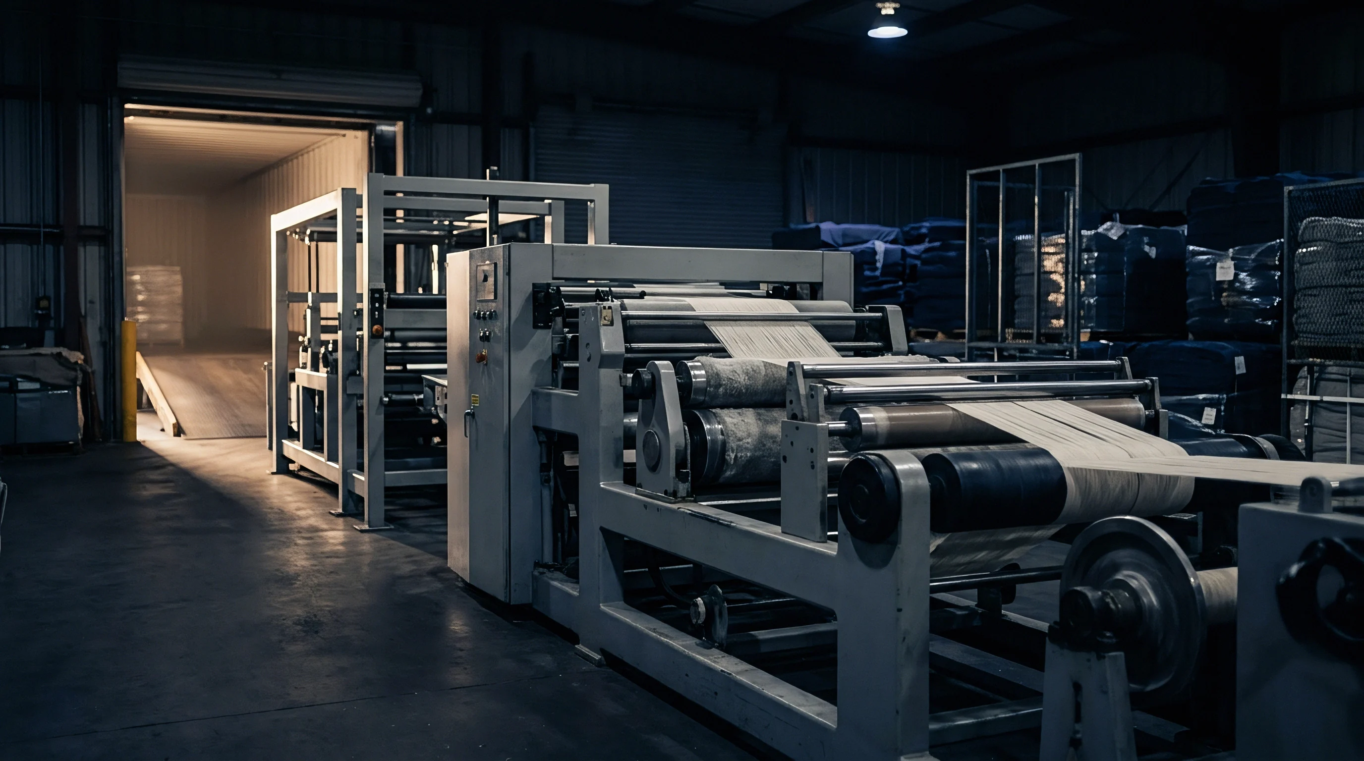
Sley drive mechanisms dictate how energy transfers from the main motor to the fell during beat-up. Modern air jet looms rely on short-stroke eccentric crank drives or conjugate cams to drive the reed toward front dead centre. At speeds over 800 picks per minute, peak reed acceleration reaches 350 metres per second squared.
High warp cover factors present stiff mechanical resistance during this brief impact window of less than 12 milliseconds. Rapid sley deceleration on fell contact sends massive shock loads back through the drive train.
Eccentric drive geometry controls how forces amplify at impact. Cams designed with longer dwell times keep the shed open for air jet filling, compressing beat-up into a narrow crank angle. That compressed window requires higher reed velocity at fell contact.
When fast-moving reed wires strike an unyielding fell, peak impact forces surge. Shock loads flex the sley shaft, throw reed alignment out, and accelerate drive bearing wear.
Dynamic balancing of the sley shaft suffers when forces fluctuate. Counterweights sized for uniform beat-up loads cannot suppress vibration spikes from varying high-density fells. When vibration frequencies hit the structural resonance of the loom frame, standing waves develop along the reed line.
These waves create local variations in beat-up force across the weaving width, leaving bands of uneven pick density down the length of the roll.
Drive Motor Torque Spikes and Energy Consumption
Electrical power draw closely tracks the mechanical load on the sley drive. Direct-drive motors adjust current continuously to maintain constant shaft speed through beat-up. Under average warp cover, motor current spikes by 40 to 60 percent over baseline at impact.
Above warp cover factor 19, those spikes jump to 180 percent above baseline, stressing motor windings thermally and raising peak demand charges across the weaving shed.
Variable load pulses also destabilize speed during air nozzle blowing windows. The main motor slows slightly under heavy beat-up impacts, causing speed fluctuations of up to 4 percent across the crank cycle. These drops disrupt the timing of main and relay nozzles synchronized to specific crank angles.
Sub-millisecond timing errors trigger pick insertion failures, nozzle blow-outs, and loose filling ends along the right selvage.
Energy recovery systems on modern air jet looms store kinetic energy during non-impact phases to cushion torque variance. Flywheels or capacitors absorb energy during shedding and release it at beat-up. While these systems steady rotational speed, they cannot eliminate force spikes at the reed wire.
High peak forces still damage warp yarns directly, regardless of motor speed controls.
- Reed Wire Deflection causes local warp end density variations across the fabric width when peak force exceeds 5000 N/m.
- Sley Bearing Pitting arises from continuous exposure to dynamic shock loads during high-cover plain weave production.
- Main Drive Belt Slippage occurs when beat-up torque spikes exceed instantaneous belt friction limits, throwing off loom synchronization.
- Profile Channel Deformation accelerates air pressure loss during insertion as reed wires flex under heavy fell contact.
- Loom Stop Sensor Trips register false warp breakage signals due to severe frame vibration during heavy beat-up cycles.

Measuring Peak Force Distributions across the Weaving Width
Sensors behind the reed plate reveal clear force differences between the drive and non-drive sides of the loom. Torsional twist along the main drive shaft causes the drive side to hit the fell slightly ahead of the far side. On wide air jet looms weaving dense industrial fabrics, this lag creates up to a 2.5-millisecond delay between drive-side and off-side contact.
The leading reed edge absorbs more energy, compressing the fell unevenly.
Piezoelectric force transducers in reed support brackets map force across the width in real time. Multi-point sensor data shows local beat-up force varying by over 30 percent across a 340 cm reed space in dense cotton weaves. Edge zones near the selvages see elevated loads from warp contraction and temple bar resistance, while the middle section flexes, reducing local impact intensity.
Fabric density profiles directly reflect these internal force spreads. Center-to-selvage density differences show up as uneven dye uptake in wet processing. High-force edge zones pack yarns tightly and restrict dyestuff diffusion, whereas softer center zones absorb more dye and appear darker.
Without careful reed alignment and sley stiffening, bulk runs end up with listing defects and horizontal shade bands.
Elevated reed wear and stop-mark spikes stem from inconsistent yarn count supply rather than uncalibrated beat-up eccentrics on high-cover air jet looms.
Strain
Cyclic Stress Profiles on Warp End Assemblies
Warp threads face heavy tensile fatigue during high-density air jet weaving. Total strain combines shedding motion extension with beat-up displacement. At front dead centre, beat-up pulls the fell forward, stretching warp ends against the back-rest roller and let-off brakes.
In high cover factor constructions, this stroke adds up to 3.5 percent strain on top of the 4.0 percent imposed by the open shed.
Peak tensile loads approach the elastic limit of staple warp yarns. In static tests, cotton yarns break at 5.5 to 7.0 percent elongation. Subjecting them to dynamic strain over 7.0 percent at 850 cycles per minute causes rapid degradation and localized breaks.
Continuous exposure to high beat-up strain destroys yarn elasticity, leaving warp ends stretched out and prone to sagging when the shed closes.
Sagging warp threads cause mispicks on shuttleless looms. A slack thread fails to clear the shed line, blocking the air channel and catching relay nozzle air streams. The resulting insertion failure stops the loom automatically, cutting weave room efficiency.
Managing warp strain requires tight coordination between let-off tension control, back-rest roller damping, and beat-up stroke geometry.
Maintaining warp strain levels below 65 percent of single-end yield strength prevents permanent yarn elongation and eliminates tension-induced stop marks.
Sizing Film Failure Modes under Heavy Impact Force
Protective size films applied during warp prep must withstand severe impact during reed contact. Modern sizing formulations use modified potato starches, polyvinyl alcohol, and acrylic binders to coat fibers and lay down surface hairiness. Under low to medium cover factors, this film acts as a flexible cushion that spreads friction and impact energy along the yarn.
High cover factors alter internal stresses within the sizing coat. Reed impact compresses the yarn, generating shear stress at the interface between size film and fiber core. Brittle sizing formulations cannot stretch to absorb this stress without cracking.
Micro-fractures develop across the film, causing size particles to flake off inside drop wires and heddle eyes.
Losing size protection exposes raw fibers to abrasive contact with reed wires and adjacent ends. Exposed fibers form pills and neps that cling to threads, driving up friction. When these entanglements reach the beat-up zone, they obstruct pick consolidation and demand even higher beat-up force.
Dust from shedding size also plugs air jet profile channels, distorting airflow and forcing manual cleaning stops.
| Sizing Composition | Size Pickup (%) | Film Elongation (%) | Friction Coeff (Yarn-Steel) | Abrasion Cycles to Failure |
|---|---|---|---|---|
| Native Starch + Tallow | 10.5 | 2.1 | 0.34 | 450 |
| Modified Starch + PVA (80/20) | 12.0 | 3.8 | 0.26 | 1200 |
| Modified Starch + PVA + Acrylic (60/30/10) | 11.5 | 5.2 | 0.21 | 2400 |
| High-PVA Pure Synthetic | 9.0 | 6.5 | 0.18 | 3100 |
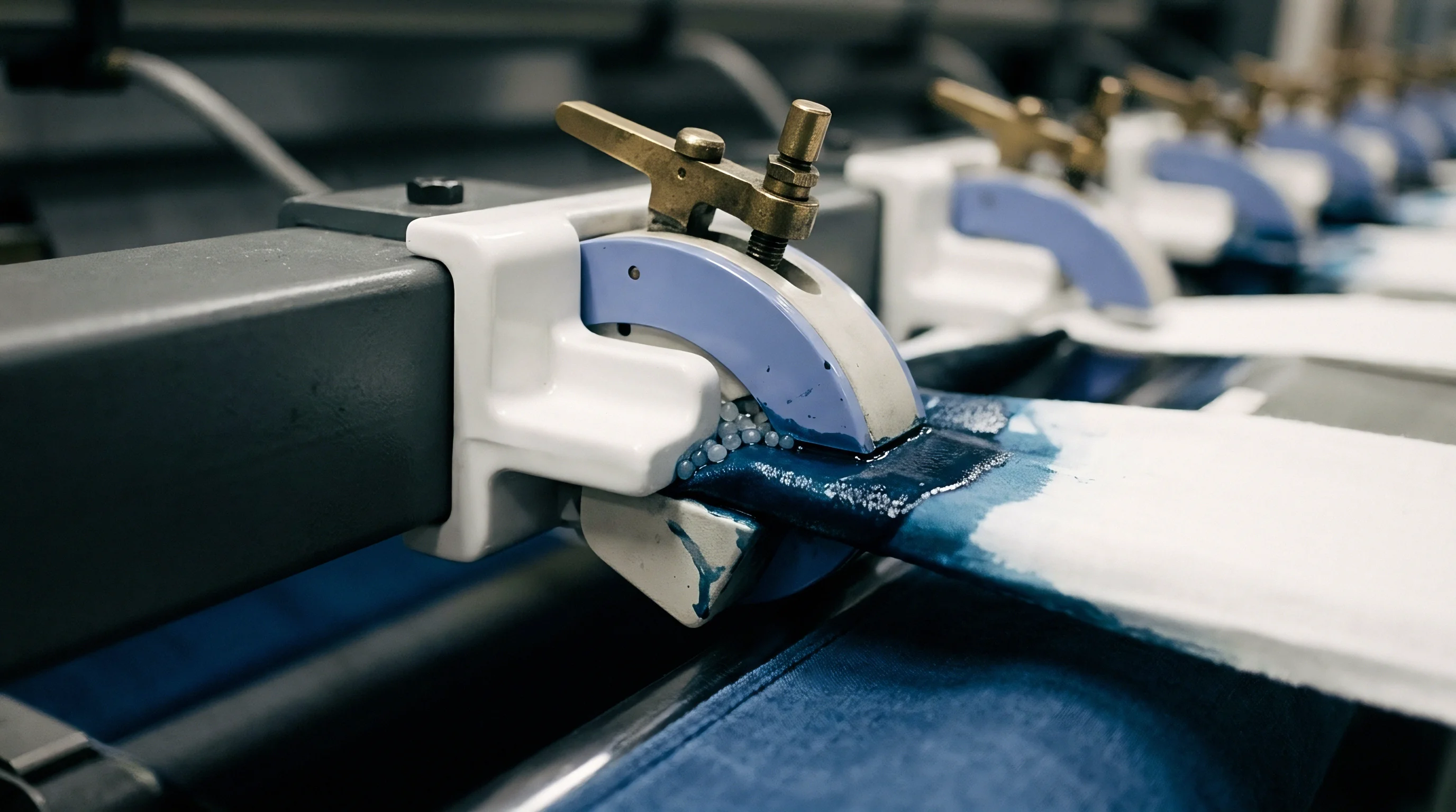
How Do Warp Sizing Formulations Suppress Cyclic Friction Spikes?
Formulating size specifically for high cover factor air jet weaving requires flexibilizers and surface lubricants. Hydrolyzed polyvinyl alcohol provides high tensile strength, while acrylic co-polymers add elasticity. Incorporating hydrogenated vegetable fats or synthetic wax emulsions lowers yarn surface energy, creating a smooth hydrophobic coating that glides through heddles and reeds.
Ultra-low viscosity size penetrates deep into ring-spun yarn cores instead of forming a thick outer shell. Deep penetration anchors interior fibers, raising tensile modulus and preventing structural collapse on impact. The thin exterior coating stays flexible, letting adjacent threads slide past one another at shed crossing without high drag.
Sizing optimized for dense weaves maintains stable friction across millions of reed strikes.
Pre-wetting warp yarns before the size box improves chemical absorption and film consistency. Running dry warp sheets through hot water pre-swells cotton fibers so size molecules distribute evenly across the yarn cross-section. Uniform coverage eliminates weak spots that would otherwise break under fluctuating beat-up loads, cutting warp breakage by up to 60 percent on high-cover looms.
Unresolved questions remain concerning how multi-layer sizing application methods affect localized stress distribution inside dense hybrid warp structures containing elastomeric synthetic cores.

Tolerance
Defining Specification Limits for High Cover Factor Builds
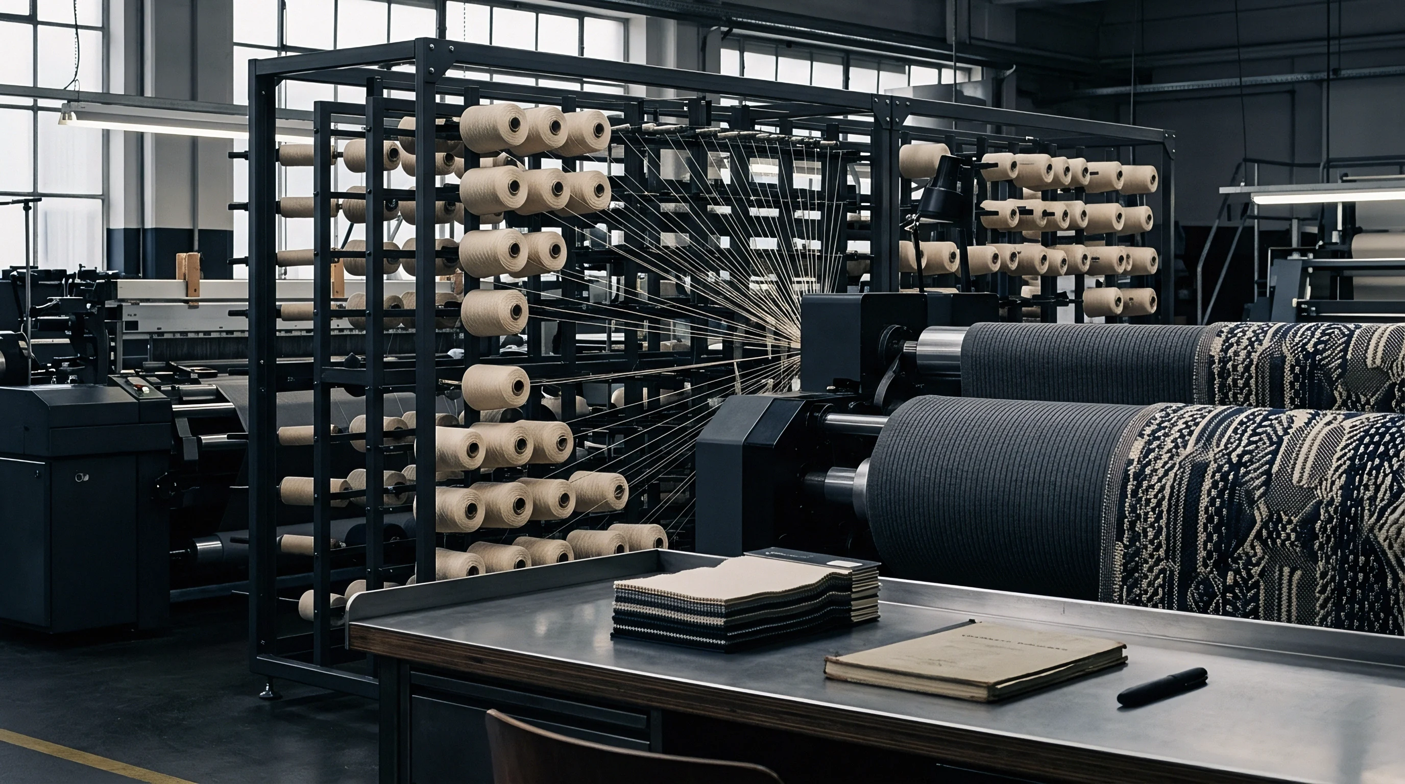
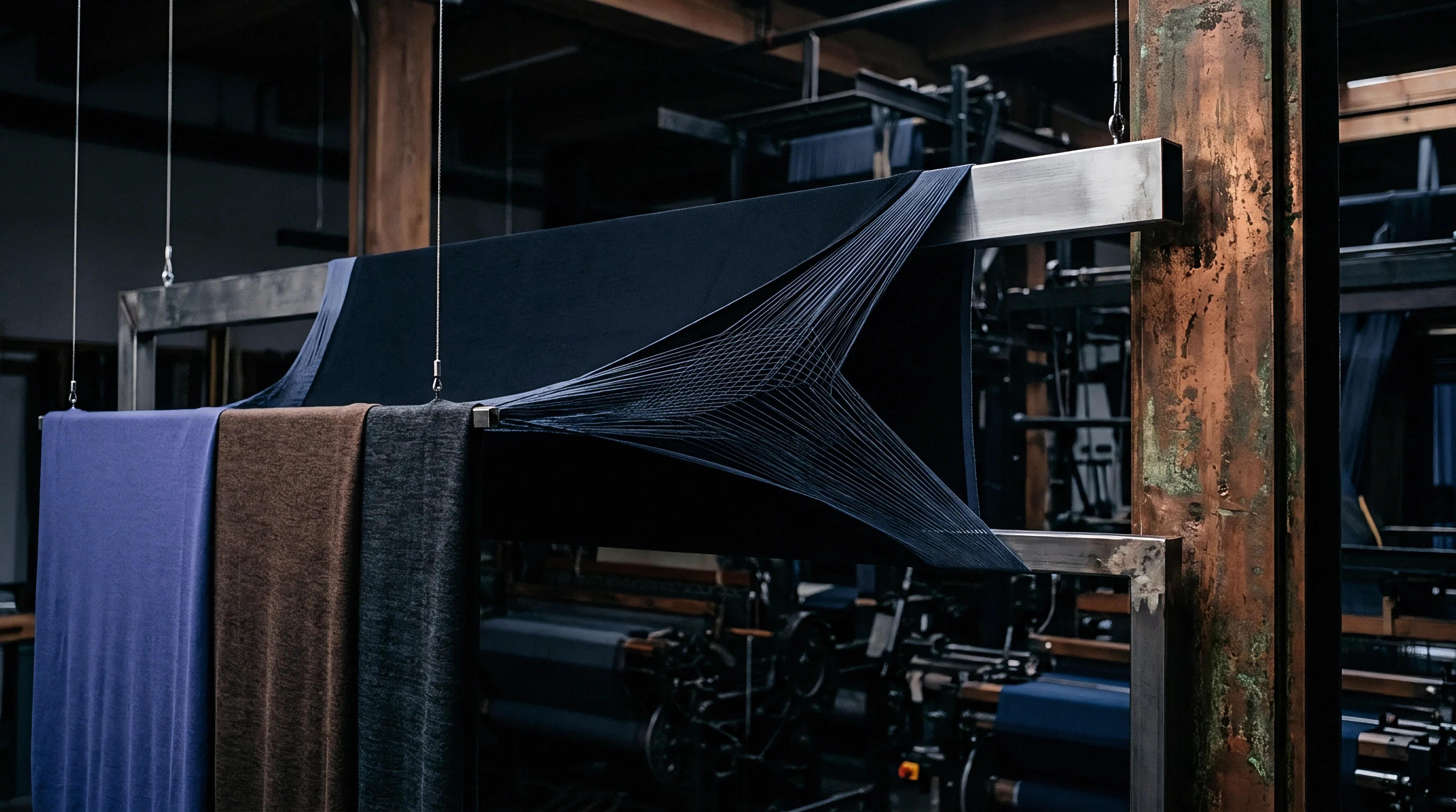
Engineering high-density woven fabrics requires narrow tolerance windows for dimensional and mechanical targets. Warp density quoted as target ends per cm must hold within plus or minus 1.5 percent across the full beam width. Exceeding target density pushes cover factor into jammed territory where force spikes exceed machine limits.
Falling short lowers fabric density below specification, compromising strength and stability.
Yarn count consistency determines cover factor stability across bulk production. A 3 percent linear density variation in 20 tex cotton yarn shifts the warp cover factor by 0.3 units. Near theoretical jamming, a 0.3-unit increase in cover factor raises beat-up resistance by up to 1200 N/m.
Weaving plants must set strict yarn count tolerances, keeping single-end CV below 1.2 percent for high-density air jet warps.
Off-loom fabric weight and sett must be measured after standardized conditioning per ISO 139 protocols. Counting threads on the loom under tension gives inaccurate readings due to yarn stretch. True cover factors are revealed by finished thread counts taken after relaxed off-loom recovery and scouring, providing dependable reference data for future batching and loom setup.
Contracts specifying fabrics with warp cover factors above 19.0 shall enforce a maximum yarn linear density tolerance of ISO 2060 Grade A with CV values not exceeding 1.2 percent.
Operational Decision Tree for High Cover Weave Execution
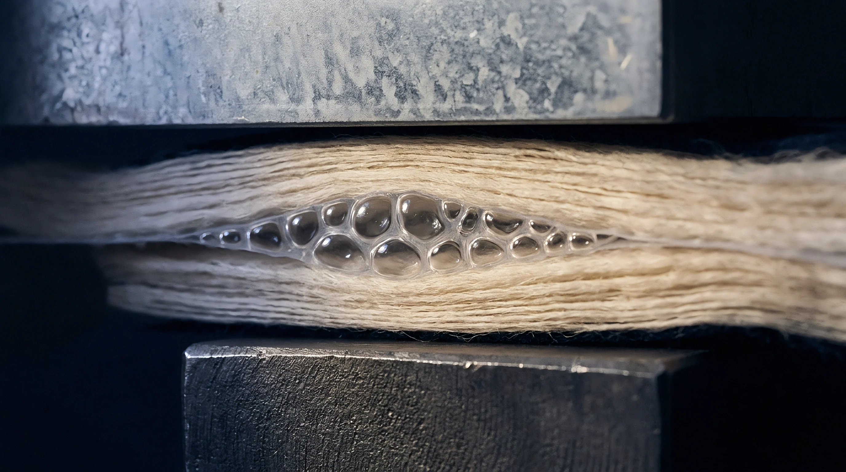
Configuring air jet looms for high warp cover requires systematic evaluation of structural limits and machine settings. The following decision pathway establishes the parameter sequence needed to balance weaving efficiency against fabric density requirements.
- Validate Cover Factor Feasibility against the loom drive power capacity and reed width dimensions before mounting warp beams.
- Select Reed Profile Geometry featuring hardened steel wires and polished air channels to minimize warp yarn friction during beat-up contact.
- Adjust Shedding Motion Timing to delay shed crossing until after beat-up completion, lowering peak warp strain at front dead centre.
- Optimize Back-Rest Roller Elevation to generate asymmetric warp shed tension, facilitating thread crossing in dense warp sheets.
- Set Let-Off Motion Sensitivity to provide smooth, continuous warp delivery, avoiding dynamic tension surges during heavy beat-up strokes.
- Calibrate Air Jet Nozzle Pressure to compensate for reduced shed clarity caused by dense warp thread proximity.
Setting Machine Parameters for Elevated Beat-Up Loads
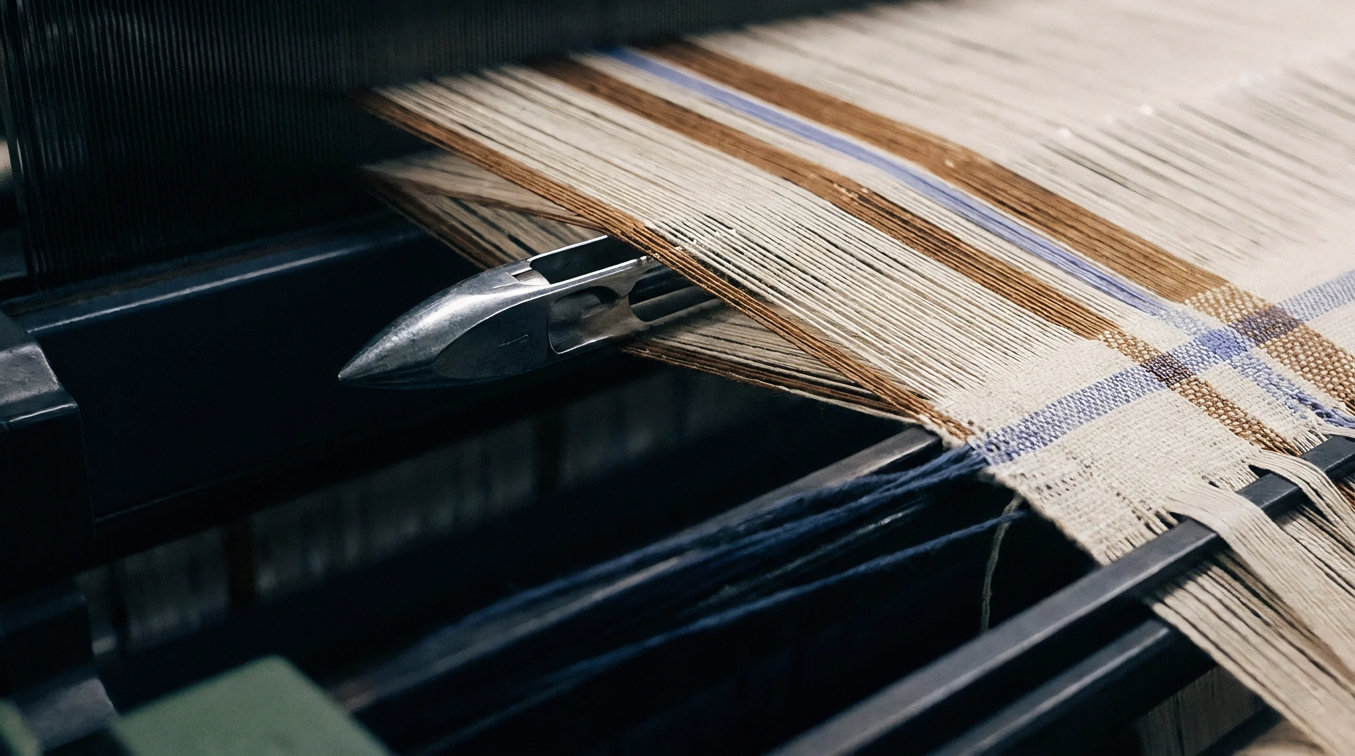
Adjusting the loom beat-up mechanism involves altering the position of the sley eccentric shaft relative to the main crank angle. Advancing beat-up timing toward top dead centre increases the mechanical advantage of the toggle linkage, raising peak force while shortening contact time. This helps seat stubborn picks in dense twills, provided the warp yarn has enough tensile strain capacity to handle the impact.
Let-off and take-up settings must stay synchronized to prevent fell drift. At high cover factors, baseline warp tension should be set as low as possible while maintaining a clean shed opening. Operating with lower baseline tension lets the fell yield slightly on impact, softening force spikes without sacrificing pick placement accuracy.
Electronic let-off controls need to react immediately to fell movement to stop beat-up force from drifting during long runs.
Temple selection affects edge-zone beat-up mechanics. Standard spiked temple rings can tear fine, dense fabrics under heavy beat-up load. Replacing them with multi-bar continuous rubber temple rollers spreads holding force evenly, stabilizing fabric width at the fell without damaging selvage yarns.
Correct temple setup prevents fell curvature and eliminates bow and skew defects across the roll.
Sourcing practices that fail to write explicit yarn CV and loom beat-up force caps into bulk purchase orders risk high off-loom reject rates, late delivery penalties, and substantial financial losses amounting to thousands of Euros per shipment.

Inspection
Identifying Defect Profiles Stemming from Beat-Up Instability
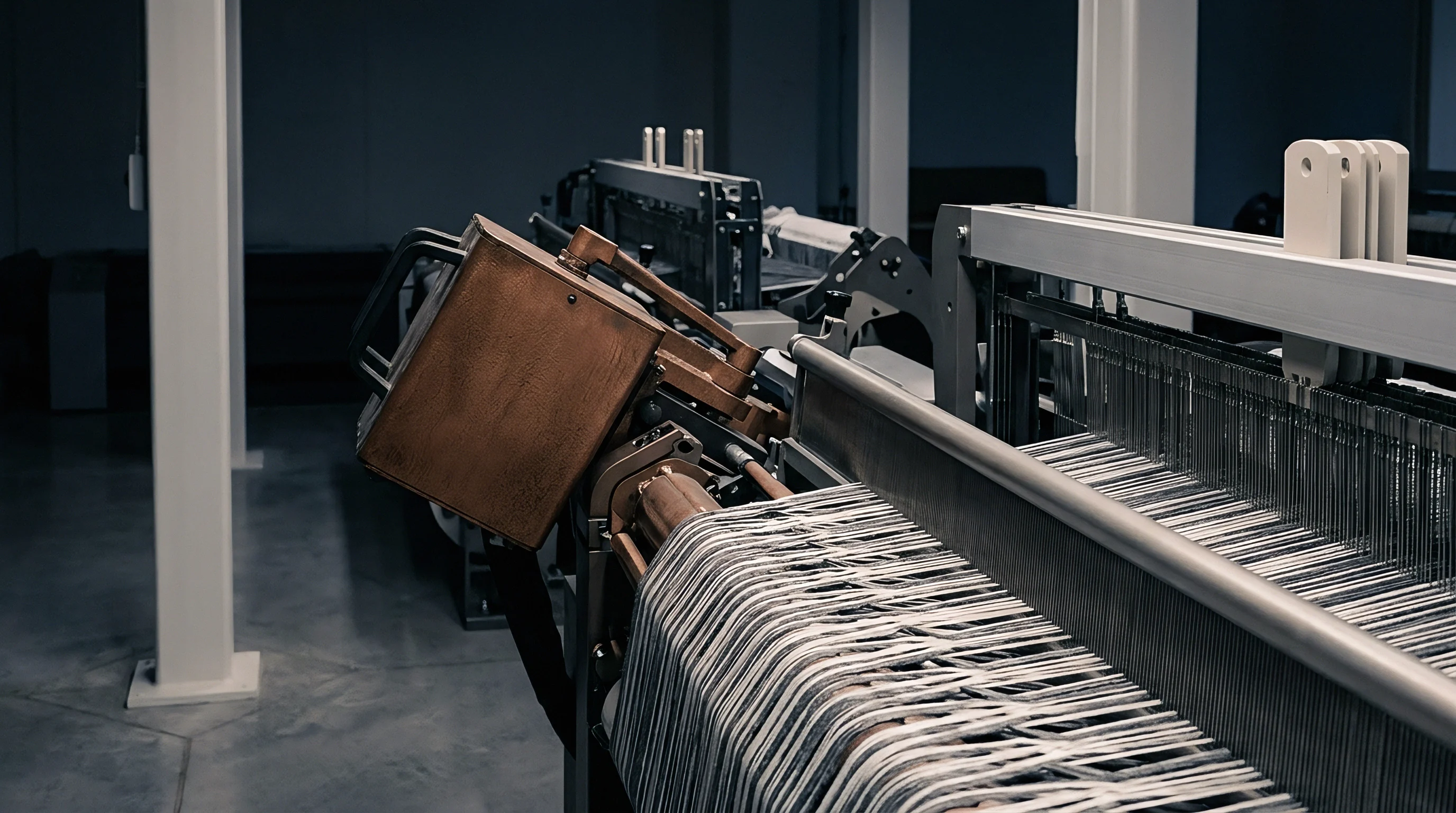
Quality inspection routines should focus on structural and visual flaws caused by inconsistent beat-up forces. The most severe visual defect is the stop mark, appearing as a high-density or low-density band across the fabric. When an air jet loom stops for a warp or weft fault, tension relaxes across the warp sheet and shifts the fell position.
Restarting without exact fell compensation causes the reed to strike too hard or too soft on the first pick, leaving a visible horizontal bar.
Reed marks are another key defect tied to high beat-up force. If peak force exceeds the lateral rigidity of individual reed wires, the wires flex sideways under load. This flexing groups adjacent warp threads together, creating permanent vertical lines along the fabric length.
Reed marks ruin fabric appearance and cause uneven dye uptake during piece dyeing, rendering the cloth unsuitable for high-end apparel.
Pick density variations ~ thick and thin places ~ occur when let-off and take-up drives fail to maintain constant tension against fluctuating beat-up resistance. In high-cover weaves, minor shifts in yarn friction cause the fell to drift back and forth. Although the take-up motion advances the cloth at a constant rate, the shifting fell creates periodic variations in pick spacing that stand out under light box inspection.
Thick and thin places occurring at regular intervals along the fabric roll indicate uncompensated mechanical backlash in the sley drive linkage.
Standard Operating Procedure for Beat-Up Defect Root Cause Analysis
Isolating beat-up defect root causes requires systematic checks on the inspection frame and weaving floor. The following steps guide technical auditors through diagnosing beat-up instability on high-cover fabric rolls.
- Mount the fabric roll on a illuminated inspection frame under standard light intensity according to ISO 8498 protocols.
- Measure the precise repeat distance of horizontal density band defects along the warp direction using a high-magnification pick glass.
- Correlate measured defect repeat distances with loom component dimensions, including take-up roll circumference and drive gear pitch circles.
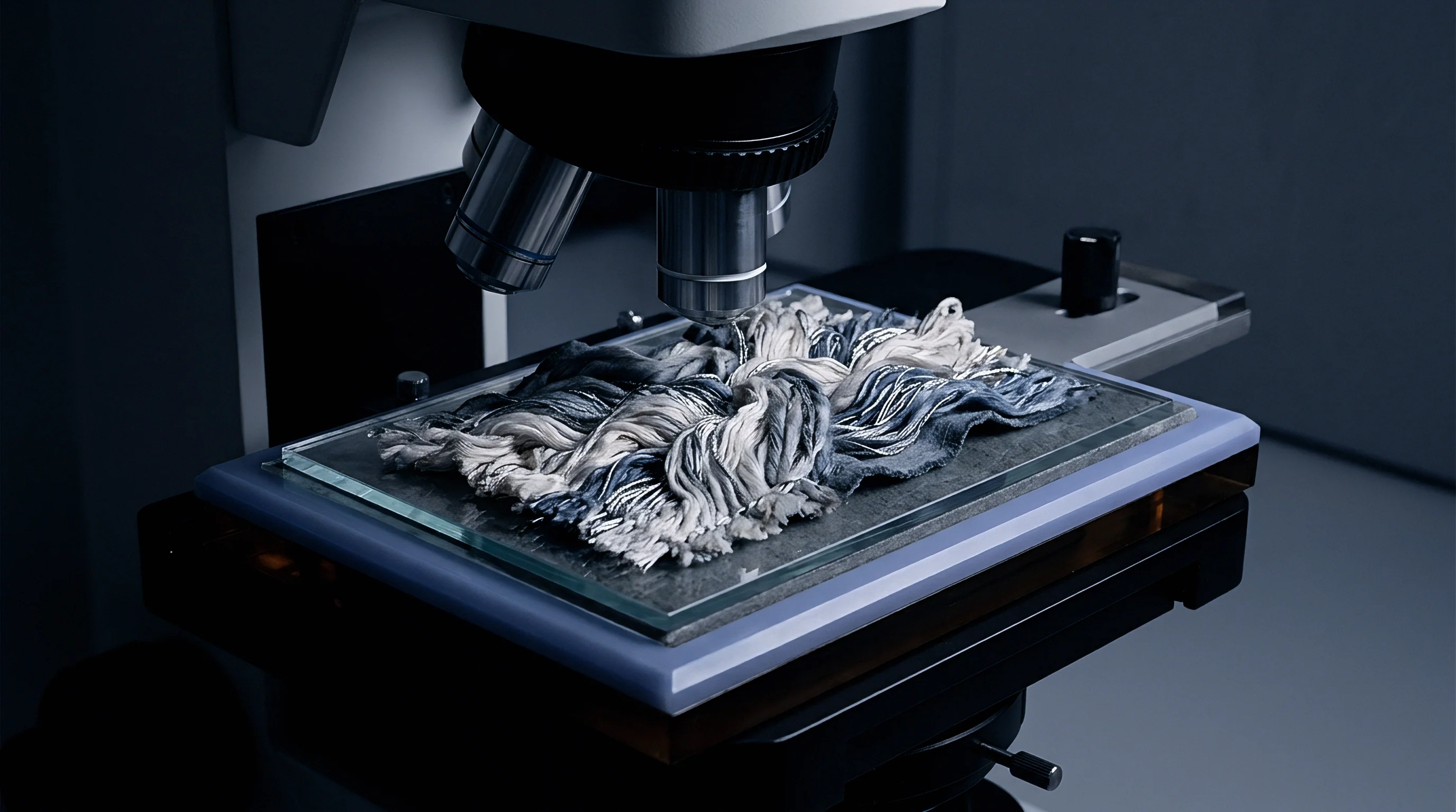
- Examine defective zones under stereomicroscopy to check for fiber abrasion, sizing film failure, or yarn flattening indicative of excessive reed impact.
- Cross-reference observed defect locations against loom stop logs to isolate stop mark events from continuous mechanical vibration patterns.
- Inspect reed wire condition on the loom to check for permanent wire bending, alignment drift, or size residue buildup in high-force strike zones.

Off-Loom Testing of Physical Performance Metrics
Physical testing reveals internal structural damage from excessive beat-up force. Tensile testing per ISO 13934-1 shows that warp yarns subjected to severe reed impact lose up to 15 percent of their ultimate tensile strength compared to yarns woven under optimized force profiles. High dynamic impact causes internal fiber breakdown that weakens threads without obvious surface damage.
Tear testing under ISO 13937-2 exposes structural jamming in dense builds. Extreme beat-up force packs warp and weft threads so tightly together that individual yarns cannot shift or bundle to resist tearing. Consequently, a fabric woven under excessive force can exhibit surprisingly low tear strength despite high thread counts and heavy weight.
Optimizing beat-up mechanics preserves thread mobility, boosting tear resistance without changing raw materials.
Air permeability testing per ISO 9237 measures structural compaction uniformity across the width. Air permeability variations above 8 percent between center and edge samples point to uneven beat-up force across the reed space. Sourcing teams should demand air permeability mapping as part of lab sample approvals for high-density technical fabrics.
A stable beat-up process yields consistent air permeability numbers and uniform thread spacing from selvage to selvage across every meter of bulk production.
Landed
Financial Impact of Low Loom Efficiency and High Stop Rates
Production costs for high warp cover fabrics depend heavily on loom efficiency. Standard air jet weaving operates at target efficiencies between 88 and 93 percent. When running high cover factors with unoptimized beat-up mechanics, frequent warp breaks and false weft sensor trips drop efficiency below 72 percent.
Each 1 percent drop in efficiency adds roughly 0.08 EUR per woven metre in fixed overhead.
Power spikes during high-force weaving add directly to conversion costs. Running air jet looms at elevated pressure to clear tight sheds increases compressor power draw. A shed producing high-cover fabrics uses up to 25 percent more compressed air volume per loom hour than standard production.
Because compressed air is one of the largest energy expenses in weaving, this translates directly into higher landed fabric costs.
Sley drive maintenance also climbs under heavy beat-up loads. Shock loads reduce the service life of reeds, drive cranks, and main bearings by more than half. Reeds on high-cover plain weaves require replacement or re-polishing after just 150,000 metres, compared to a standard reed service life over 450,000 metres.
Mills must reflect this faster spare part consumption in their base price quotes.
| Fabric Density Class | Target Cover Factor | Loom Efficiency (%) | Air Power Cost (EUR/m) | Total Conversion Cost (EUR/m) |
|---|---|---|---|---|
| Standard Shirting | 14.0 | 92.5 | 0.12 | 0.65 |
| Dense Apparel Twill | 17.2 | 87.0 | 0.18 | 0.88 |
| High-Density Down-Proof | 19.8 | 76.5 | 0.29 | 1.35 |
| Ultra-Dense Technical Cloth | 21.5 | 68.0 | 0.42 | 1.92 |
Sourcing Route Economics and Subcontract Mill Qualifications
Choosing weaving partners for high-density fabrics requires technical auditing of mill equipment. Generic mills with older air jet looms lack the sley rigidity and let-off precision needed to control beat-up force variance. Placing high-cover orders with unqualified subcontractors leads to late deliveries, high scrap rates, and severe quality disputes during final inspection.
Qualified weaving facilities run modern air jet looms with heavy-duty sley frames, direct-drive motors, and active beat-up force compensation. These machines maintain steady force profiles despite changing plant humidity or yarn lot variations. Subcontracting to specialized mills carries a higher base weaving price per metre, but it avoids bulk rejections and costly garment cutting delays further down the chain.
Landed cost calculations must incorporate finishing, freight, and scrap allowances alongside raw weaving conversion fees. Dense grey fabrics need specialized wet processing, including high-tension washing and pad-steam dyeing, to penetrate tightly packed yarns. Ignoring finishing house minimum charges and auxiliary chemical costs distorts landed cost estimates, eroding gross margins for buyers and brand owners.
Investing in premium sized compact warp yarns reduces total landed fabric cost by 0.28 EUR per metre by eliminating loom stops and raising first-quality yields.