Warp Cover Factor Calculation Equations for Woven Specifications
Warp cover factor quantifies yarn area coverage using thread density and yarn diameter equations to control fabric porosity, mechanical strength, and production speed.
Geometry
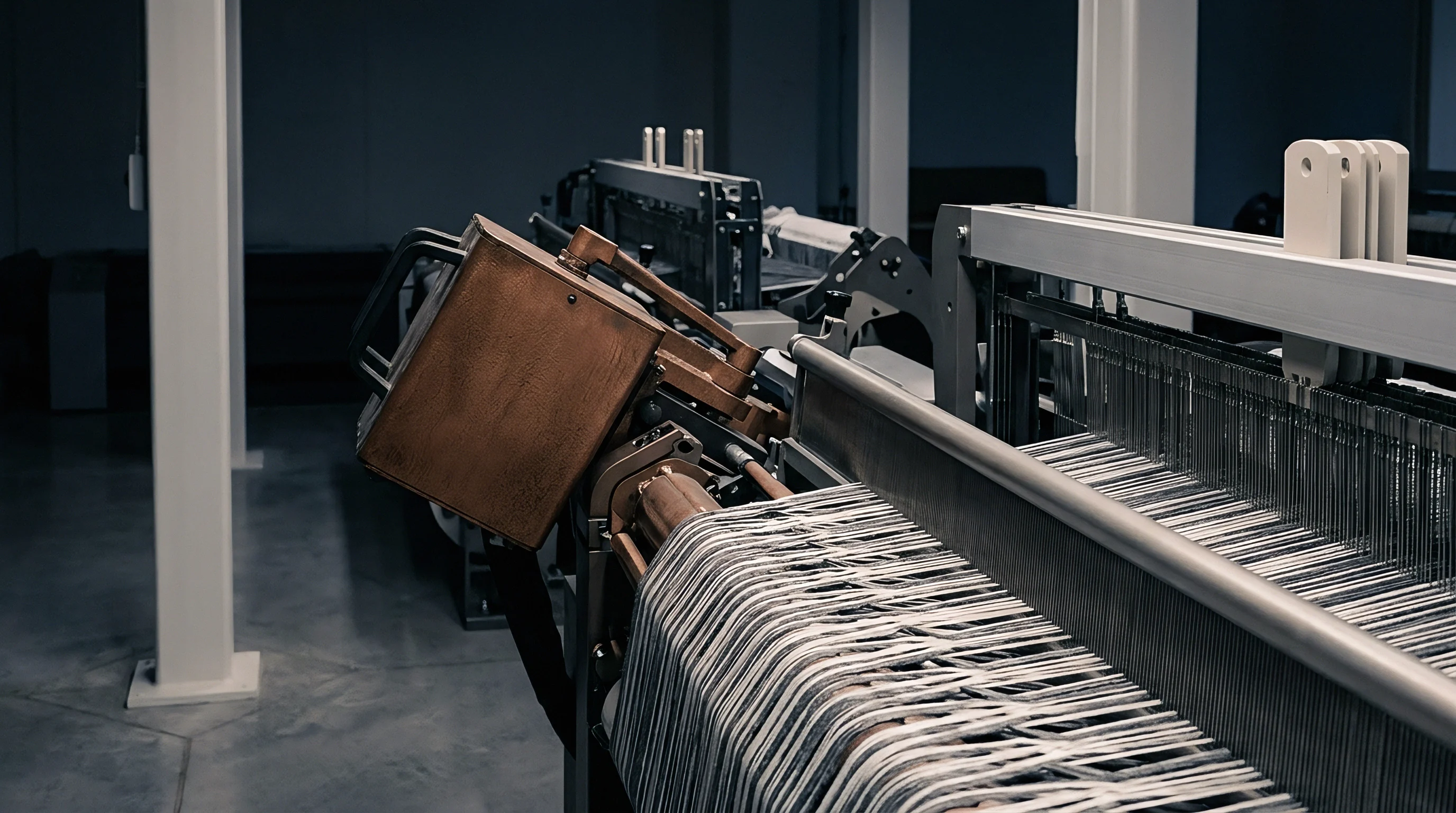
Physical arrangement of threads within a woven structure dictates both mechanical performance and visual opacity. Warp cover factor represents the ratio of the fabric surface covered by warp yarns to the total fabric area. In an idealized model, warp threads lie parallel with uniform circular cross-sections across a defined width.
Machine realities force yarn deformation under weaving tension, turning theoretical circular profiles into flattened ellipses at the crossover points.
Thread spacing matters.
Peirce developed the foundational geometric model for woven fabrics by assuming fixed thread densities and uniform yarn diameters. Yarn diameter derives directly from linear density and fiber packing density. When a warp thread sits under tension in the loom shed, its cross-sectional area deforms against opposing weft threads.
The spatial distribution of warp threads determines structural features like pore size, air permeability, and liquid barrier behavior.
A tight warp sett increases yarn friction inside the reed, elevating yarn stress before wet finishing begins.
Greige counts shift.
Calculating theoretical cover requires establishing the specific yarn diameter formula appropriate for the fiber material. For staple spun yarns, outer fibers flared by air-jet or ring spinning expand the effective boundary beyond the solid fiber core. Continuous filament synthetic yarns exhibit higher packing factors, yielding smaller effective diameters for the same linear density.
Accurate structural modeling demands using the actual compacted diameter inside the fabric matrix rather than the loose thread diameter measured off a spool.
Yarn Diameter and Spatial Distribution Mechanics
Yarn density varies.
Calculations rely on converting yarn count into an equivalent diameter expressed in inches or millimeters. In the English cotton count system, yarn diameter traditionally equals one divided by twenty-eight times the square root of the yarn count. This constant assumes a yarn bulk density of approximately 0.9 grams per cubic centimeter and a packing fraction around 0.60.
Synthetics like continuous filament polyester present higher bulk densities near 1.38 grams per cubic centimeter, requiring an adjusted multiplier in diameter calculations.
Tension changes everything.
Physical measurement of yarn diameter inside finished cloth using optical cross-sectioning reveals that flattening increases the apparent width of the yarn by ten to twenty-five percent compared to its free state. This transverse expansion increases effective warp coverage without altering yarn weight or thread count. Evaluating structural coverage requires accounting for both thread count per unit length and the altered dimensions of flattened yarns under crimp stress.
Warp threads lying in close proximity create mechanical interference during reed beat-up. Excessively high warp thread counts force adjacent threads to ride over each other, causing structural distortions known as reed marks or trailing ends. Controlling thread geometry requires maintaining sufficient spacing between adjacent warp threads to permit smooth passage of the weft during insertion.
Yarn diameter alters fabric porosity.
Sizing adds effective bulk.
Higher warp density pushes yarn crowns outward, forcing greater crimp amplitude onto the warp or weft systems depending on relative tension levels during weaving. Balancing this spatial geometry prevents structural instability while maintaining target fabric mass and physical density.
Higher warp thread density increases mechanical friction in the loom shed, creating greater yarn abrasion before wet processing line entry.
Formula
Mathematical relationship between thread spacing and yarn cross-sectional dimensions provides the quantitative basis for warp cover calculations. Multiple unit systems exist across global textile regions, demanding exact mathematical conversions between English, Metric, and Tex-based systems. Expressing warp cover factor correctly requires specifying whether the calculation uses fractional cover, percentage cover, or standard system-specific indices.

Mathematical Expressions in Traditional Systems
The traditional English cotton system defines warp cover factor, often denoted as K1 or Kw, as the ratio of ends per inch to the square root of the cotton count. This formula delivers a dimensionless index typically ranging between 10 and 28 for standard apparel and industrial fabrics.
English Warp Cover Factor equation:
Kw = EPI / sqrt(Ne)
EPI represents ends per inch in the greige or finished cloth, while Ne represents the indirect English cotton yarn count. A woven fabric with 80 ends per inch using a 40/1 Ne cotton yarn yields a warp cover factor of 80 divided by 6.325, equaling 12.65. When using worsted or woollen counts, conversions must standardise the indirect count back to the cotton equivalent or apply system-specific multipliers.
Denier-based systems calculate warp cover by converting continuous filament weight directly to thread width. In silk and synthetic filament weaving, the equivalent warp cover expression incorporates ends per inch and the square root of denier.
Filament Warp Cover Factor equation:
Kd = (EPI sqrt(Denier)) / 100
An industrial polyester taffeta constructed with 110 ends per inch of 70 denier yarn produces a cover index of 110 times 8.366 divided by 100, resulting in a warp cover index of 9.20. Converting between indirect systems and direct filament systems requires maintaining strict dimensional consistency across input variables.

SI Metric Units and Fractional Cover Derivations
International standards, including ISO methods, utilize direct Tex units to calculate warp cover. The Tex system measures mass in grams per thousand meters of yarn. The metric warp cover factor formula uses ends per centimeter and the square root of yarn linear density in Tex.
Metric Warp Cover Factor equation:
Km = (ends/cm sqrt(Tex)) / 10
Converting an English warp cover factor to a Metric warp cover factor involves a fixed conversion constant derived from unit scaling.
Km = Kw 0.957
Fractional cover represents the absolute proportion of fabric area occupied by the projection of warp threads, expressed as a number between 0.0 and 1.0. Absolute fractional warp cover, designated as Cw, incorporates the packing density and specific density of the fiber material.
Fractional Warp Cover equation:
Cw = ends/cm d
In this equation, d represents yarn diameter in centimeters. Substituting the structural density formula into yarn diameter yields the complete physical equation for fractional warp cover.
Cw = (ends/cm / 100) sqrt((4 Tex) / (10^5 pi rho phi))
The variable rho represents fiber density in grams per cubic centimeter, while phi represents the dimensionless yarn packing factor. Cotton fiber carries a density of approximately 1.54 g/cm3, whereas polypropylene presents a density of 0.91 g/cm3. Accounting for fiber density prevents structural errors when calculating equivalent spatial coverage across different fiber polymer specifications.
Specifications referencing ISO 3801 demand mass per unit area measurements on conditioned finished fabric rather than greige state off the loom.
| System Name | Input Thread Density Unit | Input Yarn Count System | Standard Calculation Formula | Conversion Factor to Metric Index (Km) |
|---|---|---|---|---|
| English Cotton System | Ends per Inch (EPI) | Cotton Count (Ne) | Kw = EPI / sqrt(Ne) | Km = Kw 0.957 |
| Tex Metric System (ISO) | Ends per Centimeter (ends/cm) | Linear Density (Tex) | Km = (ends/cm sqrt(Tex)) / 10 | Km = 1.000 |
| Denier Filament System | Ends per Inch (EPI) | Direct Weight (Denier) | Kd = (EPI sqrt(Denier)) / 100 | Km = Kd 0.300 |
| Absolute Fractional Cover | Ends per Centimeter (ends/cm) | Yarn Diameter in cm (d) | Cw = ends/cm d | Km = Cw 28.0 / sqrt(rho phi) |
Calculating total fabric cover requires integrating both warp and weft cover factors into a single fractional area coverage value. Total fabric cover, designated as Ct, prevents double-counting the square overlapping areas where warp and weft threads intersect.
Total Fractional Cover equation:
Ct = Cw + Cf – (Cw Cf)
Cw represents fractional warp cover and Cf represents fractional weft cover. A woven specification with a fractional warp cover of 0.65 and a fractional weft cover of 0.50 yields a total fabric cover of 0.65 plus 0.50 minus 0.325, equaling 0.825 or 82.5 percent spatial area coverage.
Contracts specifying physical performance under ASTM D737 air permeability limits require minimum calculated total cover values written directly into the technical schedule.
Mesh
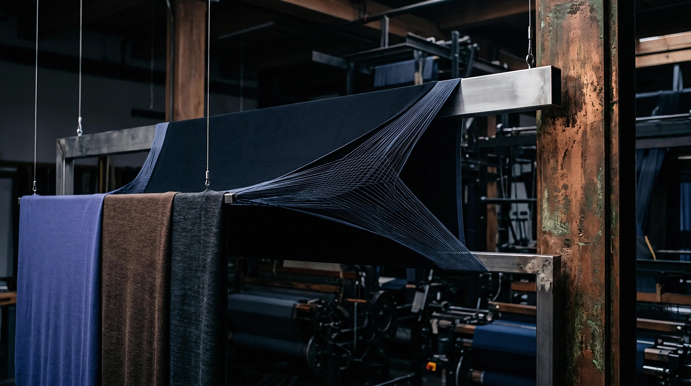
Interlacing patterns constrain how tightly warp ends pack together before mechanical binding occurs during weaving. Plain weave structures present maximum thread intersection points, creating high internal structural resistance. Twill and satin weaves reduce intersection frequency, enabling higher warp end density for the same yarn linear density.
How Does Weave Structure Limit Maximum Warp Density?
Thread crossing frequency determines the geometric space available for adjacent yarns inside the loom shed. Plain weave interlaces on a 1/1 repeat, requiring warp yarns to change shed position after every single pick. This frequent movement forces warp threads to occupy wider lateral space, imposing an absolute physical limit on maximum warp cover factor before structural jamming occurs.
Peirce calculated maximum practical cover factors for jammed structures based on geometric packing limits. In plain weave cotton fabrics, theoretical jamming occurs when the warp cover factor Kw reaches approximately 20 to 22, depending on weft cover levels. Attempting to weave a plain weave fabric above these cover levels causes high warp end breakages, severe reed marks, and loom stops.
Twill weaves interlace less frequently, floating over two or three weft picks before passing under. A 2/2 or 3/1 twill structure reduces internal spatial restriction, allowing warp cover factors to reach Kw values between 24 and 28. Satin weaves extend this principle further, floating over four to seven weft threads, enabling maximum warp cover values exceeding Kw 28 in dense lining and down-proof specifications.
| Weave Interlacing Pattern | Intersection Index Factor | Maximum Practical Kw (English) | Maximum Practical Km (Metric) | Maximum Fractional Warp Cover (Cw) |
|---|---|---|---|---|
| Plain Weave (1/1) | 1.00 | 20.5 – 22.0 | 19.6 – 21.0 | 0.73 – 0.78 |
| Matt Weave (2/2 Basket) | 0.50 | 22.5 – 24.0 | 21.5 – 23.0 | 0.80 – 0.85 |
| Twill Weave (2/1) | 0.67 | 23.0 – 25.0 | 22.0 – 23.9 | 0.82 – 0.89 |
| Twill Weave (2/2 or 3/1) | 0.50 | 24.5 – 27.0 | 23.4 – 25.8 | 0.87 – 0.94 |
| Satin / Sateen (5-end) | 0.40 | 27.5 – 29.5 | 26.3 – 28.2 | 0.92 – 0.98 |
Dyeing induces yarn shrinkage.
Reed width dictates initial density.
To avoid structural jamming while achieving target fabric weight, engineers adjust thread density parameters on the loom setup sheet using clear geometric rules.
- Yarn diameter verification using optical microscope cross-sections establishes the actual compacted yarn thickness prior to loom shed setup.
- Interlacing factor calculation adjusts maximum cover boundaries based on the selected weave repeat and float length.
- Reed dent selection matches warp yarn count with reed wire thickness to prevent reed marks and lateral thread crowding.
- Beat-up resistance monitoring identifies approaching structural jamming point before warp ends experience severe mechanical abrasion.
Finishing compacts the structure.
Failure to balance warp cover factor against weave interlacing capacity causes warp yarn shredding in the loom reed, resulting in rejected bulk rolls and unrecoverable loom downtime charges.

Contraction
Dimensional changes occurring on the wet finishing floor alter the physical spacing of threads established during weaving. Fabric leaves the loom under high longitudinal warp tension and lateral reed width constraint. Subsequent wet processing stages relaxation, scouring, dyeing, and drying release these frozen stresses, inducing substantial dimensional movements.
Warp end breakages increase rapidly.
Off-loom relaxation causes immediate grey fabric contraction. Upon releasing warp tension at the loom take-up roll, fabric contracts longitudinally while expanding slightly in width. When grey fabric enters aqueous preparation baths, yarn swelling and crimp interchange force further dimensional shifts.
Warp yarns contract in length while increasing in thread density per unit width.
Wet processing shrinkage elevates effective warp cover factors by six to fourteen percent depending on heat-setting temperatures and tension profiles.
Crimp interchange governs warp alignment.
During wet finishing, tension applied in the stenter frame alters the balance between warp crimp and weft crimp. Pulling the fabric tightly in the warp direction flattens warp crimp, forcing weft yarns to bend around straight warp ends. This structural shift reduces the effective transverse width of warp threads while pushing warp ends closer together laterally.
Conversely, high stenter clip width expansion stretches the weft, increasing finished ends per inch and driving up the finished warp cover factor.
Evaluating warp cover solely on off-loom greige counts leads to inaccurate physical specifications. A greige cotton fabric woven at 76 ends per inch on the loom can contract six percent in width during scouring and jet dyeing. The finished fabric then measures 81 ends per inch.
Assuming the yarn count remains constant, the calculated warp cover factor Kw rises from 12.01 in the greige state to 12.80 in the finished state.
High cover drops loom speed.
- Greige metric reliance causes miscalculation of finished air permeability due to uncounted wet processing thread compaction.
- Uncontrolled width stenter settings create batch-to-batch warp cover variance across different dyeing lots.
- Ignoring sizing removal swelling underestimates finished warp yarn diameter, leading to unexpected seam slippage failure under ISO 13936-1 testing.
- Resin finishing neglect overlooks synthetic polymer cross-linking that locks yarn flattening, permanently altering thread coverage.
Tighter weaves consume more yarn.
Mills frequently claim that fabric failing density checks met all original construction specs on the loom, attributing post-finishing warp cover discrepancies entirely to uncoordinated customer stenter width instructions.

Invoice
Commercial specifications tied to calculated thread cover directly govern mill production costs and yarn purchasing requirements. Warp yarn represents a fixed capital commitment prior to loom setup, requiring warp preparation, sizing, and warping processes. Specifying higher warp cover factors than end-use performance requires inflates landed fabric costs per linear meter without adding commercial product value.
Increasing warp cover factor demands either higher warp end counts or coarser warp yarn linear densities. Adding ends per inch requires more yarn spools in the warping creel, longer beam preparation times, and higher sizing chemical consumption. Sizing formulations must penetrate dense warp sheets evenly, requiring adjusted size box viscosities and higher drying energy on the sizing machine.
| Target Warp Cover Level | Loom Operating Speed (RPM) | Warp Stop Frequency (Stops/10^5 picks) | Sizing Chemical Solids Take-Up (%) | Relative Production Cost per Finished Meter |
|---|---|---|---|---|
| Low Cover (Kw 10.0 – 12.0) | 650 – 720 | 0.8 – 1.2 | 6.0 – 8.0% | 1.00 (Baseline) |
| Medium Cover (Kw 12.1 – 15.0) | 600 – 650 | 1.3 – 1.8 | 8.1 – 10.0% | 1.08 (+8%) |
| High Cover (Kw 15.1 – 18.0) | 520 – 580 | 2.2 – 3.1 | 10.1 – 12.5% | 1.19 (+19%) |
| Extreme Jammed Cover (Kw > 18.0) | 420 – 480 | 4.5 – 6.8 | 12.6 – 15.0% | 1.36 (+36%) |
Higher warp cover factors decrease weaving machine efficiency. Dense warp sheets increase beat-up resistance, forcing air-jet and rapier looms to operate at reduced motor speeds to prevent yarn breakage. High end-break frequencies demand more weaver intervention, raising direct labor costs per woven roll.
Exceeding maximum warp cover thresholds slows weaving insertion rates and raises end-break frequency per hundred thousand picks.
- Calculated warp cover factor target determines total warp end count and warping creel setup requirements.
- Sizing formulation and chemical pick-up percentages adapt to dense warp end packing to prevent yarn chafing.
- Loom speed settings adjust downward to accommodate beat-up resistance and reduce mechanical end breaks.
- Dyehouse width tension profiles adjust to deliver final finished ends per inch matching contract specifications.
- Landed fabric cost per meter accumulates cumulative cost additions from reduced loom output and increased sizing mass.
Specifying tight warp cover tolerances forces converters to audit both greige weaving logs and finishing house stenter records. When finished warp cover drifts below contractual thresholds, air permeability and tear strength metrics shift immediately out of compliance. Landed fabric invoices must reflect true finished performance rather than nominal greige loom settings.
How do mills dynamically balance sizing pickup and stenter overfeed to maintain exact target warp cover factors across variable humidity seasons?