Calculating Essential Greige Warp Set Parameters for Shuttleless Weaving
Greige warp parameters require calculating loom reed width from finished dimensions while incorporating weave crimp, size pick-up, and shuttleless selvedge waste.

Reed
Getting the effective warp width right at the loom bed requires accounting for grey fabric contraction, selvedge ends, and denting density. Shuttleless weaving machines ~ whether air-jet, rapier, or projectile ~ depend on rigid geometric boundaries across the reed space. Unlike shuttle looms, which allow the selvedge to draw in gradually, shuttleless insertion systems maintain uniform cross-machine tension, amplifying any error in width allocation.
A wrong calculation distorts warp end density, throws off insertion timing, and shifts the finished weight per unit area long before wet processing begins.
To set the correct width in the harness and reed, work backwards from the target finished state to the unconstrained greige cloth on the loom. Finished width accounts for wet processing shrinkage, dry heat relaxation, stenter frame chain settings, and mechanical tension relief. Greige off-loom width is what remains after take-up tension is released.
On-loom width, by contrast, is the distance between the outermost warp ends while under full weaving tension. Loom reed width goes further still, adding space for selvedge waste ends, tuck-in allowances, and the catch cords required for shuttleless insertion.

Width Conversion Equations and Shrinkage Factors
Designing a greige warp set starts with measuring dimensional change from the reed wires to the inspection table after finishing. Finishing contraction covers width loss during scouring, bleaching, dyeing, and drying. Weft contraction ~ or weft crimp ~ measures the wavy path that warp threads force filling yarns to follow as they interlace.
The equations for calculating loom reed width run as follows:
Warp Width Calculation ~
Greige On-Loom Width = Finished Width / (1 – Total Finishing Width Shrinkage)
Loom Reed Width = Greige On-Loom Width x (1 + Weft Crimp Fraction)
Take a 100% cotton 3/1 twill targeted for a 150 cm finished width. If lab trials show 5% finishing width contraction and 7.5% weft crimp, the greige on-loom width is 150 divided by 0.95, or 157.89 cm. Adding the 7.5% weft crimp factor pushes the required reed width to 169.73 cm across the body ends.
Selvedge structures then require additional width based on the machine’s edge termination mechanism.
Air-jet looms using pneumatic tuck-in devices need an extra 12 to 15 mm of warp space per side for stable selvedges. Rapier machines with mechanical tuckers or leno cutters require dedicated catch cords placed outside the body weave. These catch cords, often fed from separate spools, hold filling tension steady during insertion and are trimmed off after beat-up ~ a permanent yarn loss.
Adding 2.5 cm total for selvedge structures to the body reed width gives a total loom reed width of 172.23 cm.

Denting Plans and Reed Selection Mechanics
Reed count is simply the number of wire openings, or dents, per unit length. Choosing the right count means balancing warp thread distribution against friction and mechanical abrasion. High dent counts with few ends per dent yield smoother cloth, but they make reed marks more noticeable and increase yarn-to-metal chafing.
Conversely, lower dent counts packed with threads reduce wire friction but risk grouping the warp ends and leaving uneven beat-up lines.
Calculating denting space depends on total body warp ends and the chosen ends-per-dent pattern. Standard plans run 2, 3, or 4 ends per dent for plain and twill weaves, whereas heavy fabrics or dense satins might use 5 or 6. Finding the required reed count in dents per inch or centimetre comes down to warp density at the reed:
Reed Count Determination ~
Ends per Unit Width at Reed = Total Body Ends / Greige On-Loom Width
Reed Count = Ends per Unit Width at Reed / Ends Per Dent
If the target density at the reed is 32 ends per centimetre and the weave structure specifies 4 ends per dent, the required reed count is 8 dents per centimetre. Standard reed tolerances allow a variation of plus or minus 1% in dent spacing. Engineering audits check reed wire thickness alongside dent spacing, as wire gauge directly alters the open space within each dent.
| Insertion Technology | Standard Speed (RPM) | Selvedge System Type | Selvedge Space Allocation | Typical Weft Crimp Range |
|---|---|---|---|---|
| Air-Jet Insertion | 800 – 1200 | Pneumatic Tuck-In / Leno | 12 – 15 mm per side | 6.0% – 9.0% |
| Negative Rapier | 500 – 700 | Mechanical Tuck-In / Catch Cord | 15 – 20 mm per side | 5.5% – 8.5% |
| Positive Rapier | 400 – 600 | Leno and Edge Trimming | 10 – 14 mm per side | 5.0% – 8.0% |
| Projectile Insertion | 350 – 550 | Mechanical Tuck-In Mechanism | 18 – 25 mm per side | 7.0% – 10.5% |
Reed wire thickness usually ranges between 0.2 mm and 0.5 mm. Picking a wire that is too thick chokes the passage of yarn slubs, knots, and size film protrusions, driving up warp breakage on high-speed shuttleless frames running above 800 picks per minute. Open air space ratio ~ the dent opening divided by total dent pitch ~ needs to stay above 50% to prevent severe mechanical chafing on spun warp yarns.
Reed wire thickness combined with high ends per dent directly dictates warp abrasion limits on air-jet looms running above 900 rpm.
Errors in reed allocation ripple through the entire production sequence, degrading fabric quality and driving up yarn costs.
- Density distortion occurs when calculated reed width ignores wet processing width extension or relaxation, resulting in off-spec ends per inch in the finished fabric.
- Selvedge breakage rates climb when catch cord space is under-calculated, forcing insertion nozzles or rapier grippers outside their optimal mechanical timing window.
- Reed marking defects show up when low reed counts with too many ends per dent leave permanent structural streaks that survive dyehouse stenter and calendering operations.
- Filling insertion instability happens on air-jet looms when reed width exceeds the effective air profile channel, causing tip-end weft buckling and loom stops.
Getting the reed width wrong forces the loom tuner to tamper with warp tension to hit target fabric weights. Excessive warp tension pulls out crimp, distorts fabric tear strength ratios, and ruins hand feel ~ turning a theoretical calculation error into a scrap lot at the inspection table.

Crimp
The waviness introduced by interlacing dictates how much warp yarn is consumed per metre of woven greige cloth. As a warp thread passes over and under consecutive picks, its path forms an undulating profile. This physical contraction length defines warp crimp.
Calculating it accurately is essential for estimating yarn weight requirements, predicting greige fabric construction limits, and evaluating yarn strength utilization on shuttleless frames.
Warp crimp and warp take-up describe the same physical phenomenon from different mathematical angles. Warp crimp expresses yarn contraction as a percentage of woven fabric length, whereas warp take-up expresses it as a percentage of the original straight yarn length before weaving. Confusing the two introduces serious errors into warp procurement models and beam set planning.
Peirce Weave Geometry and Mathematical Equations
Classical fabric geometry models established by Peirce define how warp count, weft count, thread spacing, yarn diameter, and crimp interact. In a fully flexible model where yarns maintain circular cross-sections, yarn diameter relates directly to linear density:
Yarn Diameter Approximation ~
Yarn Diameter (mm) = 0.905 / sqrt(Yarn Metric Count Nm)
Yarn Diameter (mm) = 1.189 / sqrt(Yarn Cotton Count Ne)
Thread spacing is simply the reciprocal of thread density. When warp density is EPI (ends per inch), warp thread spacing p_1 equals 1 / EPI. When weft density is PPI (picks per inch), weft thread spacing p_2 equals 1 / PPI.
Warp crimp fraction c_1 connects to weft yarn diameter d_2, warp yarn diameter d_1, warp thread spacing p_1, and warp bending height h_1 through the fundamental geometric approximation:
Warp Crimp Percentage Formula ~
Warp Crimp % = ((L_warp – L_cloth) / L_cloth) x 100
Warp Take-Up % = ((L_warp – L_cloth) / L_warp) x 100 = (Warp Crimp % / (100 + Warp Crimp %)) x 100
To calculate crimp in a plain weave running 24 ends/cm and 20 picks/cm with Ne 30/1 ring-spun cotton warp and weft, first determine the straight yarn length L_warp needed for 100 metres of greige cloth. Lab crimp tester measurements following ISO 7211-3 yield an average warp crimp of 8.2% for this specific build under standard beam tension.
| Fabric Weave Construction | Warp Yarn Count | Weft Yarn Count | Warp Density (EPI) | Weft Density (PPI) | Warp Crimp (%) | Weft Crimp (%) |
|---|---|---|---|---|---|---|
| Plain Weave (1/1) | Ne 30/1 Spun | Ne 30/1 Spun | 80 | 70 | 7.5 – 9.5 | 6.5 – 8.0 |
| Twill 2/1 | Ne 20/1 Spun | Ne 16/1 Spun | 96 | 64 | 6.0 – 7.5 | 8.5 – 10.5 |
| Twill 3/1 Canvas | Ne 10/1 Spun | Ne 10/1 Spun | 72 | 42 | 8.0 – 10.5 | 5.0 – 7.0 |
| Satin 5 (4/1) | 40D Filament | 40D Filament | 140 | 90 | 3.5 – 5.0 | 11.0 – 13.5 |
| Ripstop Reinforcements | Ne 40/2 Spun | Ne 40/2 Spun | 110 | 86 | 6.8 – 8.2 | 7.0 – 8.8 |
Producing 1,000 metres of greige cloth requires 1,000 multiplied by 1.082, or 1,082 metres of yarn per warp end. If the warp beam carries 6,400 body ends, total yarn consumption comes to 6,924,800 metres. Converting that length to weight uses the yarn metric count: for Ne 30/1 (Nm 50.81), dividing total metres by 50.81 gives 136.29 kg of dry warp yarn, before accounting for size pick-up.

Crimp Exchange Mechanics during Loom Operation
Crimp is not a static value fixed during warp preparation. Dynamic tension from the let-off and take-up motions on shuttleless looms causes crimp exchange between the warp and weft systems. When warp tension increases, it pulls the warp ends into a flatter line, transferring the bending waves into the filling yarns.
Consequently, high warp tension lowers warp crimp while driving up weft crimp and fabric width contraction.
Shuttleless looms subject warp yarns to heavy mechanical impacts during beat-up. On rapier frames inserting coarse filling counts, high warp tension keeps the cloth structure stable but accelerates warp fatigue. On air-jet looms, however, low warp tension leads to slack sheds and filling stops.
Setting let-off tension relies on finding a crimp balance where warp thread strain stays well inside the elastic limit of the sized yarn.
Increasing let-off tension shifts crimp from the warp sheet into the weft system, reducing warp yarn consumption while increasing loom-bed width loss.
Fabric weight formulas depend directly on accurate crimp values. Calculating greige fabric weight per square metre (GSM) without correcting for crimp underestimates raw material costs:
Greige Warp Mass Contribution ~
Greige Warp GSM = (Ends per cm x 100 x (1 + Warp Crimp Fraction) x Tex) / 1000
For a greige cloth woven at 30 ends/cm with 20 Tex yarn and 8% warp crimp, warp GSM equals 30 x 100 x 1.08 x 20 / 1000, or 64.8 g/m^2. Leaving out the 1.08 crimp factor drops the calculated warp weight to 60.0 g/m^2 ~ an 8.0% accounting error. Over a 50,000-metre production run, that mistake hides more than 2,400 kg of yarn.
Higher pick counts raise warp crimp because warp ends must cross more interlacing points per centimetre. Similarly, coarser weft yarns force warp ends to travel around a larger cross-sectional arc during shedding and beat-up, further increasing warp crimp.

Tension
Dynamic strain on warp ends during shed formation directly controls end breakage rates on high-speed shuttleless looms. With speeds exceeding 1,000 picks per minute on modern air-jet frames, cyclic stress on warp threads becomes severe. Peak tension hits during shed opening and beat-up.
Designing a warp set without checking dynamic strain limits leaves the process vulnerable to end breaks, accelerated harness wear, and structural fabric defects.
Shedding geometry dictates how much geometric stretch a warp end undergoes as the harness moves. Total strain during shed opening is the sum of structural extension and geometric extension. That combined strain fraction must stay below the sized yarn’s yield point to prevent permanent stretch or direct tensile failure.
Shedding Geometry Strain Calculations
Geometric strain from shedding depends on harness depth, shed height, and the distance from the cloth fell to the back rest roller. As harness frames move from closed to fully open shed, warp yarns are pulled into top and bottom shed lines, and that path extension generates dynamic tension.
Shed Line Extension Equation ~
L_open = sqrt(L_front^2 + (H_shed / 2)^2) + sqrt(L_back^2 + (H_shed / 2)^2)
Warp Extension Strain = (L_open – L_closed) / L_closed
Here L_front is the distance from cloth fell to harness frame, L_back is from harness frame to back rest roller, and H_shed is total shed height at the harness line. On a rapier loom where L_front is 300 mm, L_back is 900 mm, and H_shed is 60 mm, L_open works out to 301.498 mm plus 900.500 mm, or 1201.998 mm total. With L_closed at 1200 mm, yarn stretch per stroke is 1.998 mm ~ an operational geometric strain of 0.166%.
Beat-up introduces a sharp impulse strain when the reed pushes the filling pick into the cloth fell. Dense fabric constructions increase beat-up resistance, driving the cloth fell forward during reed contact. This fell movement requires higher static let-off tension to hold position, pushing cyclic tension peaks up to 30 ~ 50 grams per end.
Cover Factor Limits and Loom Weaveability
Density limits dictate whether a warp set will actually weave on a shuttleless frame. Fractional cover factor measures the proportion of fabric area covered by warp and weft yarns. For Cotton Count Ne, Peirce warp cover factor K_1 comes from:
Peirce Fractional Cover Factor ~
Warp Cover Factor K_1 = EPI / sqrt(Ne_warp)
Weft Cover Factor K_2 = PPI / sqrt(Ne_weft)
Total Fabric Cover Factor K_c = K_1 + K_2 – (K_1 x K_2 / 28)
In SI units (ends per cm and Tex), maximum theoretical cover factor equals 1.0, where adjacent threads touch without flattening. In practice, the upper limit for shuttleless weaving depends on insertion mechanics, shed clarity, and sizing strength.
| Yarn Fiber & Structure | Yarn Count (Ne) | Max Practical EPI | Warp Cover (K_1) | Air-Jet Limit (K_c) | Rapier Limit (K_c) |
|---|---|---|---|---|---|
| 100% Combed Cotton Ring | Ne 40/1 | 120 | 18.97 | 24.5 | 26.2 |
| Carded Cotton Ring | Ne 20/1 | 84 | 18.78 | 23.8 | 25.5 |
| Polyester/Cotton Blend | Ne 30/1 | 112 | 20.45 | 25.0 | 27.0 |
| Viscose Filament | 150 Denier (Ne 35.4) | 118 | 19.83 | 24.0 | 25.8 |
| Textured Nylon 6,6 | 70 Denier (Ne 75.9) | 160 | 18.37 | 23.2 | 25.0 |
Pushing an air-jet cover factor past 25.0 causes warp threads to cling during shed opening. That clinging prevents clean shed separation, interfering with the main air stream and causing filling insertion stops.

Where Does Beat up Resistance Peak in High Density Builds?
Fell displacement reaches peak force when warp and weft cover factors cross critical density thresholds together. Tight warp packing keeps weft picks from sliding easily into position on the reed’s forward stroke. A comparative analysis across three density bands on air-jet machinery demonstrates how high thread density affects warp tension profiles.
Worked Comparative Sensitivity Band Analysis ~
An evaluation covers three variations of a 100% combed cotton plain weave (Ne 40/1 warp and Ne 40/1 weft) across a 170 cm reed width running at 850 RPM. Static let-off tension is adjusted in each case to keep the cloth fell position constant.
Case A (Standard Density) ~ Sett 90 EPI x 80 PPI. Warp cover K_1 = 14.23, Weft cover K_2 = 12.65. Total cover K_c = 20.44.
Load cell transducers record peak dynamic warp tension at 18.2 grams per end. Loom efficiency averages 94.5% over 24 hours.
Case B (High Density) ~ Sett 110 EPI x 90 PPI. Warp cover K_1 = 17.39, Weft cover K_2 = 14.23. Total cover K_c = 22.79.
Peak dynamic warp tension rises to 28.6 grams per end, with fell displacement reaching 2.4 mm per beat-up stroke. Loom efficiency holds at 91.2% with occasional warp stops.
Case C (Extreme Density Limit) ~ Sett 128 EPI x 100 PPI. Warp cover K_1 = 20.24, Weft cover K_2 = 15.81. Total cover K_c = 24.62.
Peak dynamic warp tension spikes to 44.1 grams per end. Fell displacement exceeds 4.8 mm, bringing heavy warp abrasion, size film breakdown, and an unacceptable stop rate of 8.5 warp breaks per loom-hour.
- Install dynamic strain load cell sensors beneath the back rest roller support brackets to monitor real-time tension spikes in the warp sheet.
- Measure static baseline tension with harness frames leveled at mid-stroke before turning on the loom.
- Record peak tension values across at least 50 consecutive shedding cycles at operating speed.
- Measure fell displacement using non-contact laser sensors focused on the cloth fell line during beat-up impact.
- Adjust let-off motion control response until dynamic peak-to-valley tension variance falls below 25% of baseline static tension.
When dynamic tension during shed opening exceeds 30% of single-end sized yarn tenacity, yarn extension capacity is exhausted. Cumulative fatigue forms micro-cracks in the size film, causing fiber fuzz, end entanglement, and eventual warp breaks.
Where exactly tension spikes trigger non-linear strain failure depends on yarn hairiness and how well the size binder handles high-frequency cyclic loading.
Sizing
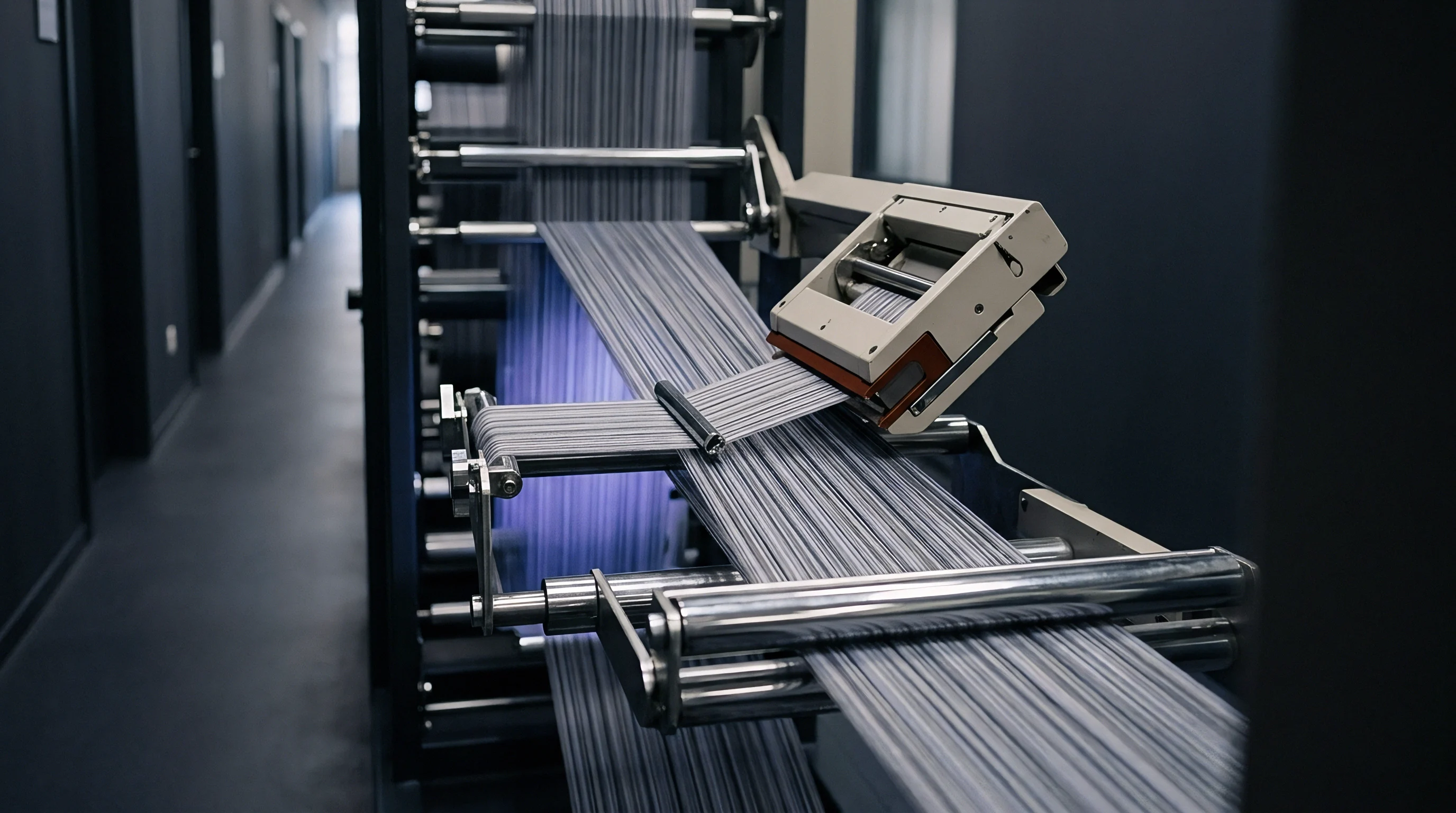
Polymer encapsulation applied during beam preparation turns weak, hairy spun yarns into durable structures that can handle weaving stresses. Unsized spun warps simply lack the abrasion resistance and tensile uniformity needed for high-speed shuttleless looms. Air-jet weaving demands minimal hairiness so ends won’t cling in the shed, while rapier weaving requires tough surface abrasion resistance against gripper passage.
Slashing operations must deliver precise chemical solids pickup while keeping yarn stretch within narrow limits.
Sizing calculations center on dry size pick-up, size box concentration, squeeze roll pressure, and creel stretch control. Getting these settings right ensures complete yarn encapsulation without making the warp brittle or difficult to desize in wet processing.
Dry Size Pick-Up Calculations
Dry size pick-up measures the net weight of dry size solids added to the unsized warp yarn, expressed as a percentage. Too little pick-up leaves surface fibers exposed, forming fuzz balls behind the reed. Too much pick-up stiffens the yarn, cuts down elongation at break, and increases chemical consumption during desizing.
Dry Size Pick-Up Percentage Formula ~
Size Pick-Up % = ((Weight of Sized Dry Warp – Weight of Unsized Dry Warp) / Weight of Unsized Dry Warp) x 100
To hit a target dry size pick-up, the slasher operator calculates size box liquor concentration based on wet pick-up performance. Wet pick-up is the mass of liquid size solution absorbed by the warp relative to dry unsized yarn mass before reaching the drying cylinders:
Wet Pick-Up and Concentration Equation ~
Wet Pick-Up % = (Mass of Liquid Size Solution Absorbed / Unsized Dry Warp Mass) x 100
Required Size Concentration % = (Target Dry Size Pick-Up % / Wet Pick-Up %) x 100
If a slasher running carded cotton warp achieves 110% wet pick-up under 20 kN squeeze roll pressure and the target dry pick-up is 11.0%, the required refractometer solids concentration is 11.0 divided by 1.10, or 10.0% dry solids in the size box.
Wet pick-up levels vary inversely with slasher squeeze roller pressure and warp yarn packing density across the size box immersion roller.
Formulating size requires matching film properties to fiber content and loom insertion method. Standard recipes blend primary binders like modified starches or polyvinyl alcohol (PVA) with secondary binders such as acrylic copolymers and lubricant waxes.
- Air-jet sizing formulations focus on hairiness reduction, using higher PVA or acrylic ratios to glue down surface fibers and keep sheds clear.
- Rapier sizing formulations emphasize film toughness and surface lubrication, relying on higher wax content to minimize metal chafing from rapier guides.
- Water-jet sizing formulations use water-insoluble acrylic polymers or ester starches that hold up against high-pressure water sprays.
- Filament warp sizing formulations use low-viscosity acrylics or polyester resins built for thin surface coating rather than filament penetration.
Controlling stretch during slashing is just as vital as managing size pickup. Tension between creel beams, size boxes, drying cylinders, and headstock pulls on warp yarns throughout preparation. Excessive stretch strips out natural yarn elasticity and reduces elongation at break.
Slasher Stretch Strain Calculation ~
Slasher Stretch % = ((Delivery Speed – Creel Feed Speed) / Creel Feed Speed) x 100
For spun cotton warps, slasher stretch should stay below 1.5%; for synthetic filaments, it must remain under 0.5%. Pushing cotton stretch past 2.0% destroys yarn elasticity and can drive up warp breaks on high-tension shuttleless looms by more than 40%.
Fabric specification contracts standardly include clauses limiting slasher yarn stretch to a maximum threshold of 1.25 percent to preserve residual warp elongation.
If slasher speed increases without a matching increase in squeeze roll pressure, wet pick-up spikes. That extra moisture overloads the dryer section, leaving damp warp beams that can mildew in storage and cling heavily in the weaving shed.
While bumping up size pick-up by two percentage points is sometimes thought to fix high loom stop rates, adding size without sufficient softening wax simply makes the yarn brittle, leading to shear fractures under beat-up impact.
Allowance
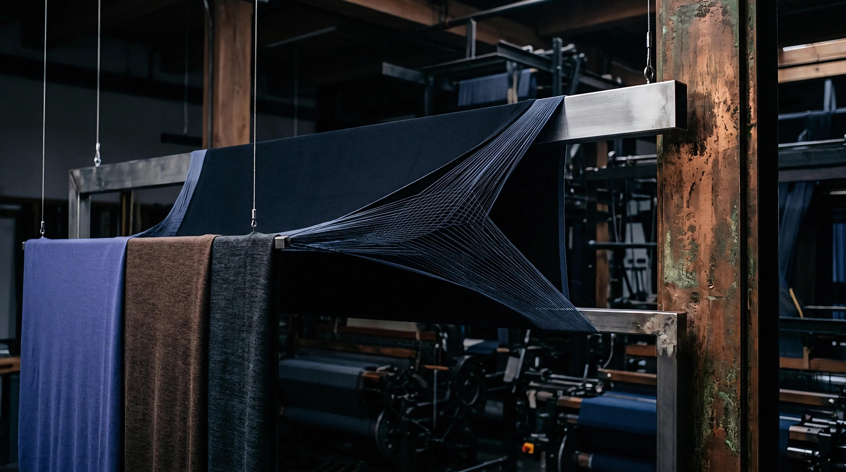
Converting thread counts into accurate raw material orders requires accounting for thread waste, selvedge discard, and beam contraction. Buying yarn based strictly on theoretical fabric weight leads to shortages or leftover inventory at the end of a run. A proper warp calculation tracks every mass loss mechanism from warping and slashing through weaving and inspection.
Warp accounting spans five distinct loss points: creel remnant waste, slasher headstock waste, loom tie-on waste, selvedge discard, and inspection sampling cuts. Factor all of these in, and theoretical warp numbers translate cleanly into real purchase orders.
Component Breakdown of Warp Waste Allocations
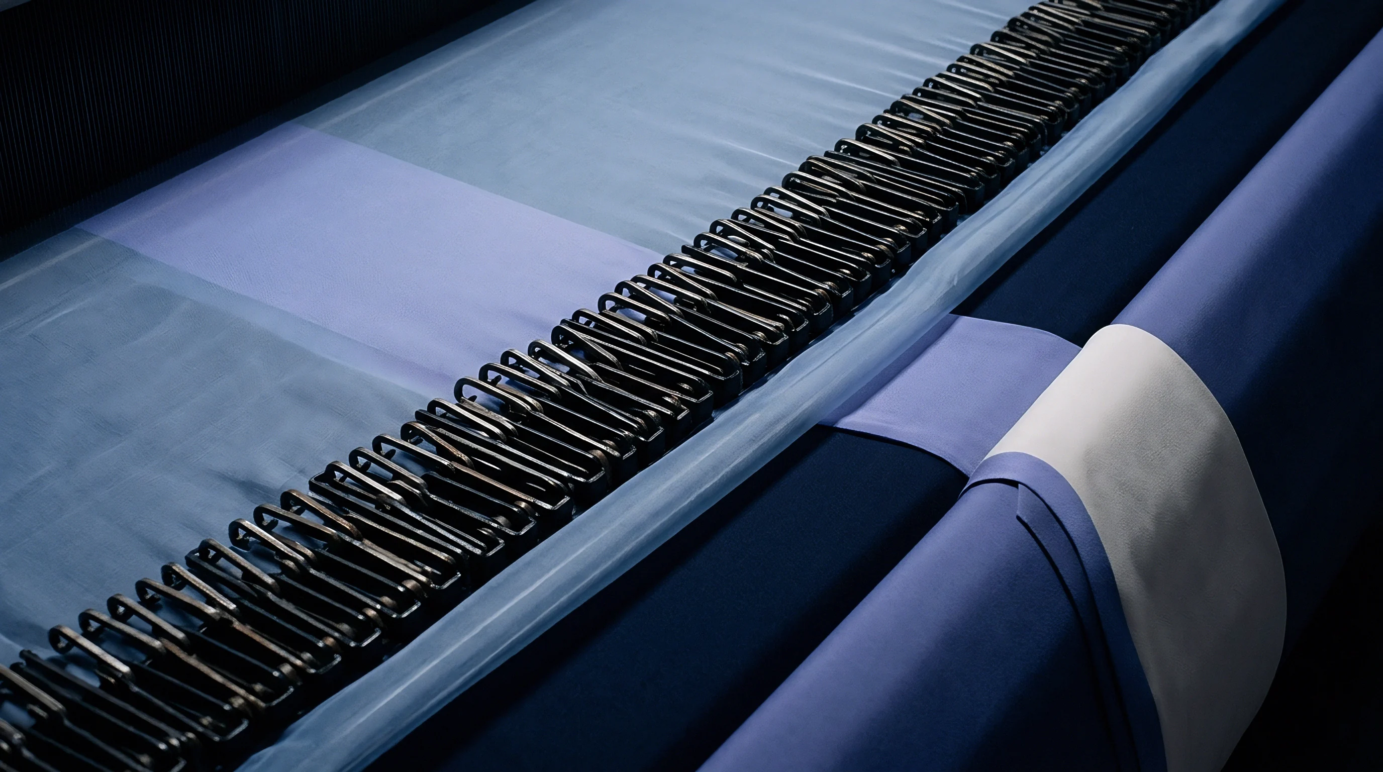
Creel waste occurs when bobbins unspool down to their cores. Small tension variances leave residual yarn packages (bobbin ends) that cannot be wound onto warp beams. In modern automatic warping plants, creel waste averages 0.5% to 1.0%.
Slashing waste comes from lead-in alignment, size box threading, and damaged headstock ends during beam changes. A 10-beam slashing set typically generates 20 to 35 metres of full-width waste, or roughly 0.3% to 0.6% total length loss on a 5,000-metre run.
Loom tie-on waste occurs when mounting a new beam on the weaving frame. Automatic knotting machines require 0.8 to 1.2 metres of warp length per beam installation. Both slasher waste and tie-on losses are fixed length losses, regardless of total beam length.
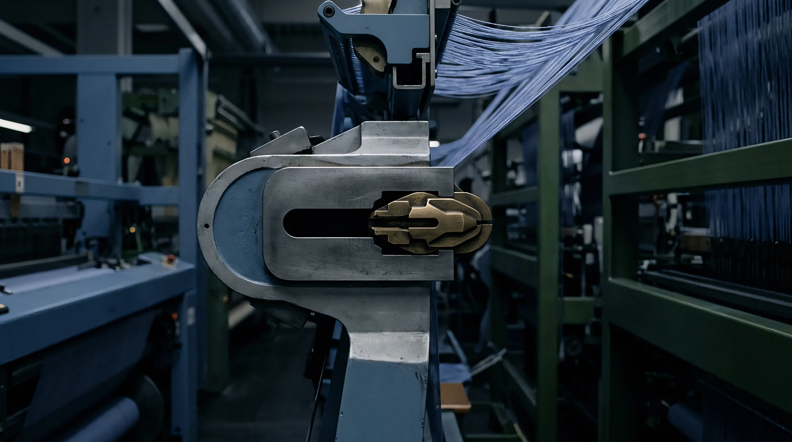
Selvedge waste is permanent loss created during shuttleless insertion. Tuck-in systems trim yarn tails, leno cutters create fringe waste, and rapier catch cords run continuous extra ends outside the body weave. These catch cord threads run parallel to the body ends but feed directly into waste bins right after beat-up.
| Insertion System | Selvedge Type | Catch Cord Requirement | Fixed Waste / Set (m) | Process Waste (%) | Total Warp Allowance Factor |
|---|---|---|---|---|---|
| Air-Jet Loom | Pneumatic Tuck-In | None Required | 30 – 45 | 1.2% – 1.8% | 1.025 – 1.035 |
| Air-Jet Loom | Leno & Trim | 2 to 4 Ends per Side | 30 – 45 | 2.5% – 3.8% | 1.040 – 1.055 |
| Rapier Loom | Mechanical Tuck-In | None Required | 35 – 50 | 1.5% – 2.2% | 1.030 – 1.040 |
| Rapier Loom | Leno & Catch Cord | 4 to 8 Ends per Side | 35 – 50 | 3.0% – 4.5% | 1.048 – 1.065 |
| Water-Jet Loom | Leno Melt-Sealed | 2 to 4 Ends per Side | 25 – 40 | 2.0% – 3.2% | 1.035 – 1.048 |
Master Equation for Total Warp Mass Requirement
Finding the total warp yarn mass needed for a given contract length means pulling end counts, crimp, size pick-up, selvedge allowance, and process waste into a single equation:
Master Warp Mass Equation ~
Total Warp Ends = (Greige On-Loom Width x Ends/cm at Reed) + Selvedge Ends + Catch Cord Ends
Warp Mass per Metre (g/m) = (Total Warp Ends x Tex x (1 + Warp Crimp Fraction) x (1 + Size Pick-Up Fraction)) / 1000
Total Yarn Required (kg) = (Target Fabric Length (m) x Warp Mass per Metre (g/m) x Process Waste Factor) / 1000
A full allocation calculation applies to a bulk order of 20,000 metres of greige twill woven on a rapier loom with leno cutters and catch cords. Specifications call for 160 cm greige width, 32 body ends/cm, Ne 20/1 warp yarn (29.5 Tex), 7.0% warp crimp, 10.0% dry size pick-up, 8 catch cord ends (29.5 Tex), and 40 body selvedge ends. The process waste factor is 1.042 (4.2% total waste).
Multiplying 160 cm by 32 gives 5,120 body ends. Adding 40 selvedge ends and 8 catch cords brings total warp ends to 5,168. Warp mass per metre works out to 5,168 x 29.5 x 1.07 x 1.10 / 1000, or 179.37 grams per metre.
Total yarn mass required for 20,000 metres comes to 20,000 x 179.37 g/m x 1.042 / 1000, or 3,738.27 kg of unsized Ne 20/1 yarn. Subtracting size pickup leaves the net raw fiber requirement, while sizing inventory must allocate 373.83 kg of dry size solids for the set.
Calculating warp yarn procurement without adding dedicated catch cord ends creates a systematic yarn shortage of up to 80 kilograms per 50,000-metre production set.
Standard purchase contracts require delivered greige warp weight to stay within plus or minus 1.5% of master yarn weight calculations after moisture conditioning per ISO 139 specifications.