Calibration Model for Optical Edge Detection Bias across Textured Fabric Finishes under Tensile Loading
Dynamic tensile load alters surface texture scatter, shifting optical edge detection boundaries; calibration models must couple strain to filter parameters.


Grain
Automated visual inspection systems on web processing lines and tensile testing frames register fabric edges by tracking spatial intensity gradients across camera sensor arrays. When textured textiles undergo axial tension, surface topographies collapse, reorient, and alter local light scattering profile boundaries. Machine vision algorithms detect threshold crossings where grey-level values drop sharply across adjacent pixel rows.
On finished surfaces carrying structural depth, directional illumination creates shadow valleys that mimic or displace true physical material edges.
Shadows migrate under stress. A machine vision sensor configured for flat, untextured woven grey goods fails when evaluating heavy piqué knits, 3/1 twill denim, or brushed fleece under tension. Tensile loading pulls high-twist yarns into flatter cross-sections while opening inter-yarn voids.
Specular reflection peaks move away from yarn crowns toward the trough between warp and weft floats. An edge extraction system relying on Fixed Thresholding or standard Sobel gradient filters misinterprets this reflection displacement as a physical lateral expansion or contraction of the web boundary.
| Surface Finish Topology | Baseline Roughness (Ra, micrometres) | Tensile Load Strain (Percent) | Illumination Angle (Degrees off-axis) | Apparent Edge Bias (Millimetres) |
|---|---|---|---|---|
| Single Jersey Knit (Unfinished) | 18.4 | 5.0 | 15 | +0.14 |
| Single Jersey Knit (Unfinished) | 18.4 | 20.0 | 15 | +0.42 |
| 3/1 Warp-Faced Twill (Calendered) | 8.2 | 5.0 | 45 | -0.08 |
| 3/1 Warp-Faced Twill (Calendered) | 8.2 | 15.0 | 45 | -0.29 |
| Piqué Honeycomb Structure | 42.1 | 10.0 | 30 | +0.86 |
| Heavy Raised Fleece (Napped) | 65.0 | 10.0 | 30 | +1.24 |
Lighting geometry dictates the magnitude of optical edge migration. Telecentric lenses paired with collimated backlight illumination eliminate edge parallax, but backlit configurations fail on dynamic production lines where mechanical webs pass over solid anvil rolls or wide-width tensioning drums. Directional front lighting generates strong topographical micro-shadows that shift when tension aligns disordered surface fibres along the stress vector.
The optical detector interprets grey-level transitions at shadow boundaries as physical edge locations, introducing systematic measurement errors that scale dynamically with applied strain.
A 12 percent elongation in a 3/1 twill construction shifts the apparent optical edge boundary outward by 0.38 millimetres under 500 lux directional ring lighting.
Tension distorts light scattering. Surface finish treatments aggravate this bias by altering surface energy and bidirectional reflectance distribution functions. Fluorocarbon water-repellent coatings create specular micro-beads on protruding yarn crowns, while mechanical calendering flattens surface ribs into reflective ribbons.
Under tensile force, calendered ribbons tilt away from the camera optical axis, extinguishing specular return signals at the outer web border and forcing sub-pixel line fitting algorithms to lock onto interior shadow boundaries instead.
- Specular peak migration occurs when yarn crown flattening under axial load alters the angle of maximum reflectance away from sensor axes.
- Shadow valley collapse develops as high-tension state flattens structural floats and narrows inter-yarn gaps, shifting perceived contrast gradients inward.
- Fibre realignment noise manifests when napped or brushed surface filaments orient along strain paths, scattering fringe illumination into camera apertures.
- Poisson edge rounding creates local light leakage at fabric borders where edge yarns untwist and fray under direct tensile jaw clamping.
Equipment manufacturers frequently assert that high-resolution sensor grids and neural network edge classifiers completely eliminate texture noise during high-speed tensioning cycles.

Strain
Tensile stress alters fabric geometry through yarn crimp interchange, structural shear, and Poisson contraction. In woven structures, tension along the warp direction straightens warp yarns while forcing weft yarns into higher crimp amplitudes. This mechanical transformation changes the spatial frequency of the surface texture profile.
An optical camera observing an unstrained fabric registers a dominant spatial frequency corresponding to the relaxed thread count per centimetre. As tensile load builds, thread pitch changes non-linearly across the field of view.
The weave flattens rapidly. Yarns rotate under load. Spatial domain edge detection operators such as Canny or Laplacian of Gaussian assume a stationary spatial reflectance noise distribution.
When tensile loading stretches the substrate, that assumption breaks. The filter kernel width, optimized for relaxed fabric texture, becomes misaligned with the altered spatial pitch of the strained yarn floats. Sub-pixel interpolation routines then select secondary contrast peaks generated by rotated yarn crowns rather than the true material boundary.
Coarser surface yarns produce shadows that migration routines register as physical fabric movement whenever tension flattens the structural weave.
Sub-pixel intensity profiles across an optical edge follow a step-like transition softened by lens point-spread functions and surface scatter. Tensile deformation introduces a dynamic optical blur along this profile. Cross-directional contraction causes edge yarns to tilt out of plane, creating an inclined optical surface relative to the imaging sensor.
The edge transitions from a step boundary to a low-gradient ramp. Fixed threshold processing methods register this ramp flattening as a lateral shift of the fabric border, recording artificial dimensional changes up to five times greater than actual physical necking.
- Structural crimp interchange alters warp and weft thread density, changing spatial surface texture frequencies during loading sequences.
- Cross-directional necking causes out-of-plane rotation of border yarns, converting sharp step edges into wide optical transition ramps.
- Unraveling fringe dynamics generates floating transient edge artifacts as individual filament ends pull free from yarn bundles under extreme stress.
- Polarized light rotation occurs in synthetic multifilament structures when stress birefringence changes surface light reflectance under cross-polarized illumination setups.
Uncompensated optical vision tools tracking width during ISO 13934-1 strip tensile tests systematically overestimate lateral strain parameters on coarse weave structures. Calibration against stationary metal plates or precision glass reticles fails to correct this error. Glass reticles maintain absolute boundary contrast under all lighting conditions, presenting no mechanical deformation, texture shifting, or surface light scatter.
Dynamic calibration requires correction factors derived directly from substrate morphology and current strain states.
Valid calibration protocols couple visual edge positioning to real-time tensile strain inputs through surface reflectance transfer functions.
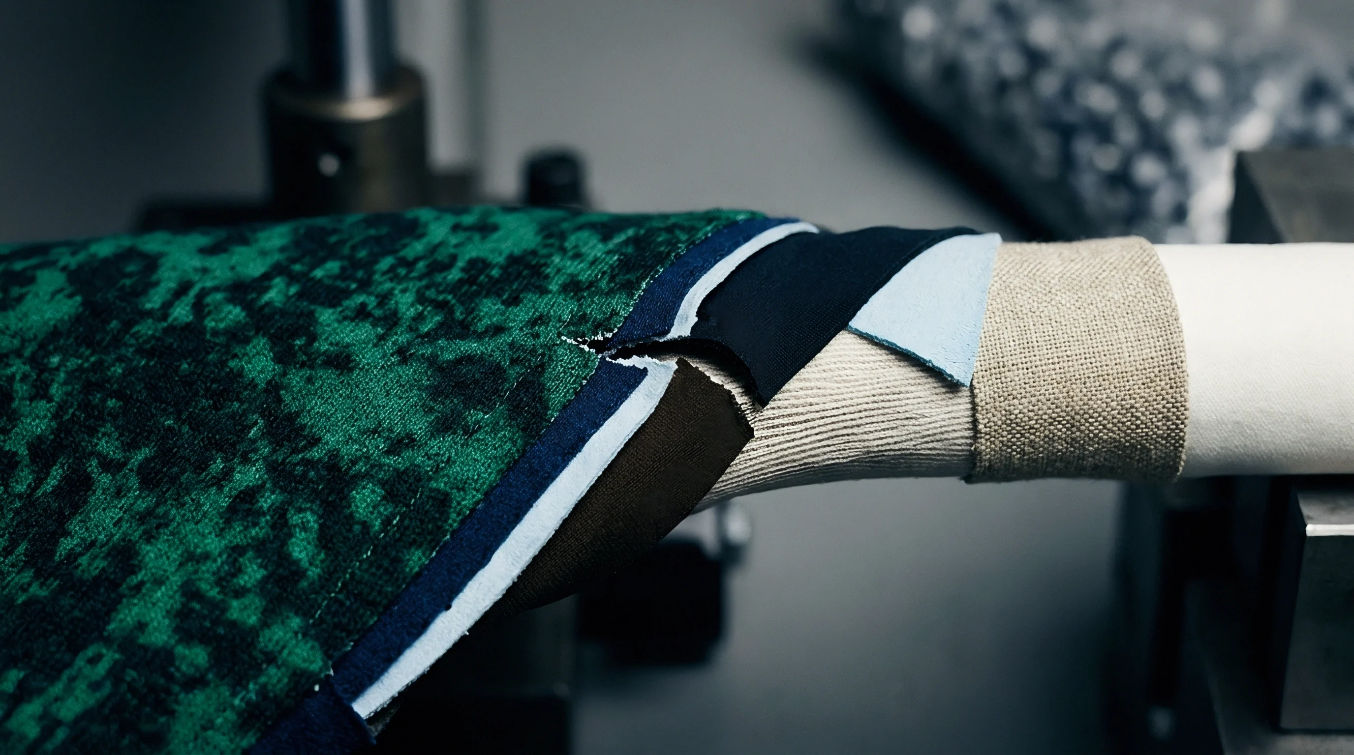

Kernel
Algorithmic compensation for optical edge bias requires converting grey-level sensor arrays into true physical spatial coordinates through strain-dependent filter adaptation. Conventional edge extraction uses continuous spatial convolution, evaluating local image intensity gradient vectors across horizontal and vertical axes. Standard derivative operators calculate maximum gradient values across localized pixel neighborhoods, but surface finishes on textured textiles introduce high-frequency optical noise that distorts gradient amplitude peak locations.
How Does Specular Shadowing Induce Edge Bias under Load?
Gradients move across pixels. Specular highlights and directional shadows displace local intensity maxima away from actual physical boundary lines. Under zero-load conditions, a 2D intensity profile across a fabric edge displays high spatial frequency ripple superimposed on a macro-step function.
Applying tensile load changes both the frequency and amplitude of the ripple. Standard Canny hysteresis thresholds either discard true material edges or lock onto internal shadow ridges created by structural floats. Correcting this systematic error demands dynamic scaling of Gaussian smoothing variance parameters based on real-time tensile feedback.
| Algorithm Variant | Sub-Pixel Method | Mean Edge Bias (Pixels) | Std Deviation (Pixels) | Processing Latency (ms) |
|---|---|---|---|---|
| Standard Sobel Operator | Intensity Centroid | +3.42 | 0.88 | 1.2 |
| Canny Edge Detector | Hysteresis Thresholding | +1.85 | 0.54 | 4.5 |
| Zero-Crossing Laplacian | Second Derivative Fit | -2.10 | 0.72 | 2.8 |
| Adaptive Texture Spline | Dynamic Gaussian Surface Fit | +0.12 | 0.09 | 14.1 |
| Bi-Directional Gradient Filter | Strain-Coupled Profile Matching | +0.04 | 0.05 | 18.6 |
Precision optics demand spatial ground. The mathematical correction model constructs a tension-dependent transfer function that adjusts sub-pixel edge positions based on measured material strain and finish surface metrics. Image brightness profile I(x,y) across an edge is modeled as the convolution of physical edge step function S(x), point-spread optical function P(x), surface reflectance function R(x, epsilon), and illumination scattering matrix L(theta).
The dynamic edge position correction model evaluates spatial shift delta-X using the following operational sequence.
Compliance with ISO 13934-1 strain evaluation without dynamic edge bias compensation invalidates sub-millimeter width verification during high-speed tensile loading.
- Capture dynamic high-resolution image frames of fabric edge boundaries while simultaneously recording synchronization timestamps from load cell amplifiers.
- Extract raw one-dimensional intensity profile vectors orthogonal to the approximate edge line across a minimum sampling width of sixty-four pixels.
- Calculate current spatial texture frequency metrics by performing fast Fourier transforms on interior fabric region sample blocks adjacent to the edge zone.
- Adjust spatial Gaussian filter kernel width sigma dynamically as a function of measured spatial texture frequency decay and axial tension inputs.
- Convolve vector profiles with adapted derivative kernels to establish spatial intensity gradient profiles stripped of yarn-level specular noise.
- Execute sub-pixel edge fitting using zero-crossings of second-derivative Gaussian polynomials matched to current material strain states.
- Apply offline-calibrated offset surface lookup matrices mapping surface roughness Ra and strain percentage directly to lateral pixel shift values.
Edge tracking fails silently. Implementing uncalibrated sub-pixel edge routines on automated web processing equipment leads directly to false out-of-tolerance width alerts, causing unnecessary production line stops and invalid roll rejections.

Proving
Validating an optical edge bias calibration model requires empirical verification against independent physical measurement standards during active mechanical loading. Laser Doppler velocimeters and contact mechanical micrometer jaws provide reference baselines, but non-contact optical laser line displacement meters set to high precision offer the cleanest cross-validation for textile web boundaries. The calibration rig mounts an accredited ISO 17025 load cell onto an optical bench equipped with telecentric backlight illuminators, multi-angle directional front lights, and sub-micron linear encoders.
Texture alters spatial gradients. The verification process evaluates target fabrics across complete load-unload hysteresis curves. Test swatches undergo controlled uniaxial tension according to ASTM D5034 grab methods or ISO 13934-1 strip procedures while machine vision sensors and laser displacement gauges log edge positions simultaneously at sampling frequencies exceeding 100 Hz. Comparing raw vision data, calibrated vision data, and laser gauge baselines establishes absolute calibration accuracy across varying strain intervals.
Machine vision reads local contrast. Discrepancies between visual edge positions and laser displacement metrics highlight regions where surface finishes break down under stress. For example, calendered wax finishes flake or delaminate under high strain, creating localized light-scattering debris that disturbs sub-pixel fitting algorithms.
Identification of these failure thresholds prevents false web width logging during high-speed coating operations.
Audit records must trace calibration validity back to primary physical targets under certified laboratory ambient conditions. ISO/IEC 17025 accredited laboratories demand complete measurement uncertainty budgets covering illumination voltage fluctuations, camera thermal drift, tension cell hysteresis, and fabric surface roughness variances. Calibration files without documented strain-bias correction vectors fail brand audits during automated defect compliance disputes.
Sub-pixel interpolation algorithms track intensity gradients rather than physical mass distribution when shear angles alter surface reflectance.
Laboratory validation procedures verify calibration performance before deploying optical detection algorithms into real-time quality control environments:
- Reference standard alignment verifies that telecentric laser gauge beams align parallel to camera sensor planes within a tolerance of 0.05 degrees.
- Illumination stability verification measures light source intensity variations across five-hour operational windows to isolate drift from texture scattering effects.
- Multi-angle contrast profiling evaluates edge gradient response under front lighting angles from 15 to 75 degrees in 15-degree increments.
- Hysteresis curve tracking evaluates calibration matrix accuracy during both ascending load cycles and descending mechanical relaxation phases.
Whether calibration transfer matrices derived under static laboratory tension hold equal validity on high-speed continuous web converting lines running at three hundred metres per minute remains open to empirical challenge.
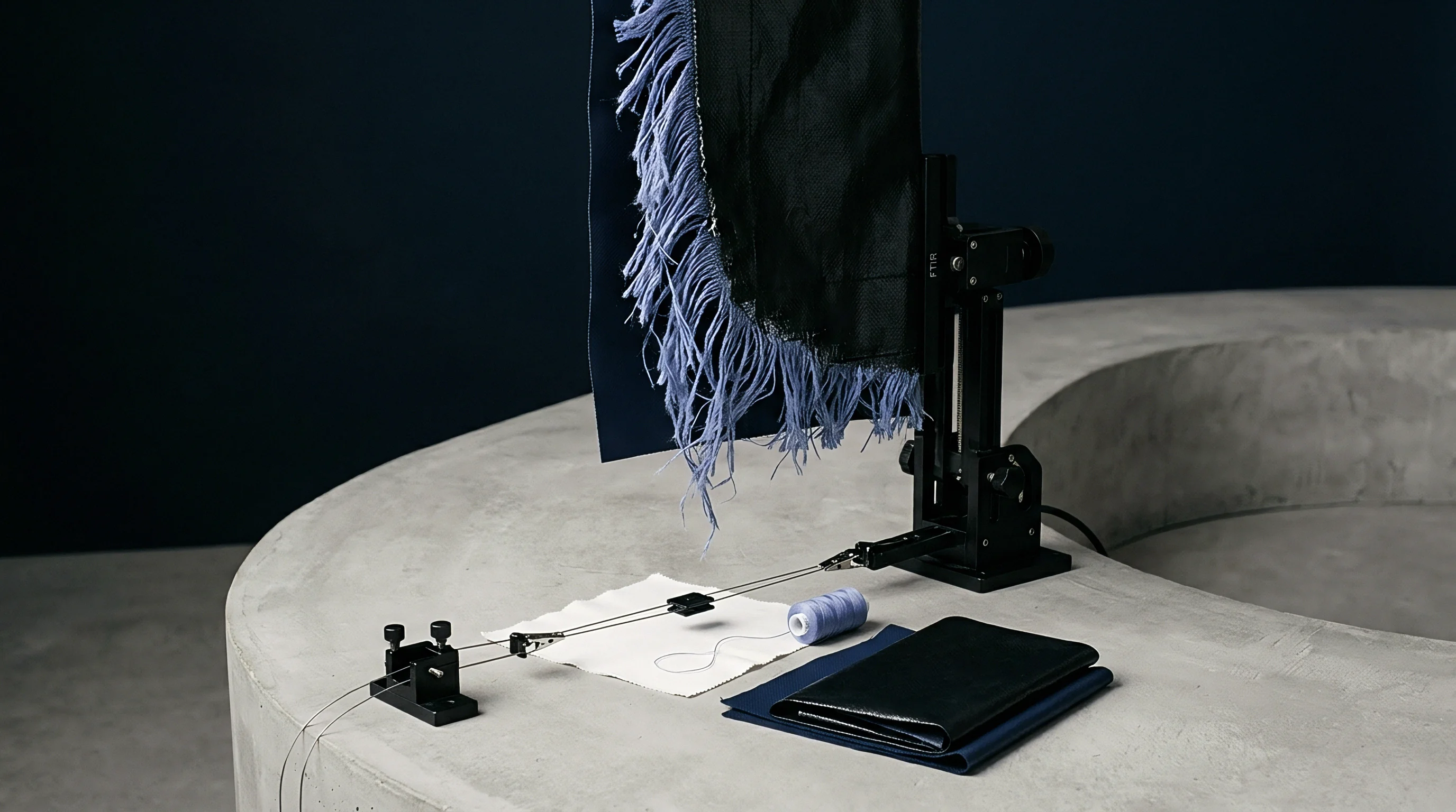
Exposure
Uncorrected optical edge detection bias introduces significant financial liability across cross-border textile supply chains. Automated web-guiding and edge-trimming systems rely on real-time vision inputs to maintain width specifications and optimize cut yields. When vision systems misinterpret shadow shifts as material width drift, active steering roll actuators overcorrect, creating physical web skew, edge wrinkling, and excessive selvedge trim waste.
In high-speed coating and laminating operations, false edge tracking causes uneven chemical application along borders, leading to wide roll rejections during end-article quality audits.
Width metrics drift wide. A converter buying technical fabrics on spec sheets requiring tight mill-width tolerances risks holding non-compliant inventory if mill-floor vision systems rely on uncalibrated optical edge sensors. When a brand audit tests landed rolls using contact physical calipers or telecentric backlit laboratory frames, recorded roll widths frequently fall below purchase order minimums.
The resulting non-conformity claims stall customs clearances, trigger inventory write-downs, and force costly re-inspection protocol execution at port warehouses.
| Process Operation | Web Speed (m/min) | Optical Edge Bias Range (mm) | Operational Failure Mode | Estimated Direct Scrap / Penalty Cost |
|---|---|---|---|---|
| High-Speed Slitting and Rewinding | 350 | 0.5 to 1.2 | Excessive selvedge trim and uneven roll profiles | USD 2,400 per 10,000 m batch |
| Functional Coating and Laminating | 120 | 0.8 to 2.5 | Uncoated border zones and adhesive bleed-through | USD 8,500 per container load |
| Automated Garment Pattern Cutting | 45 | 0.3 to 0.9 | Pattern piece dimension drift and panel misalignment | USD 1.15 per cut garment unit |
| High-Tension Technical Web Guiding | 200 | 1.0 to 3.0 | Web wrinkling and steering-induced edge tearouts | USD 12,000 machine downtime event |
Contractual limits apply strictly. Sourcing contracts covering high-value technical textiles, protective apparel substrates, or automotive interior fabrics mandate documented measurement system analysis studies. Master purchase agreements increasingly include explicit compliance terms governing vision system calibration under dynamic tension.
Incorporating calibrated strain-bias mathematical models into automated inspection protocols protects buyers and converters from unevidenced quality rejections while ensuring mill shipments conform to physical dimensional criteria under all operating loads.
Standard supply contracts specify that dimensional measurement non-conformities identified during brand audits trigger full batch re-testing costs charged directly to the weaving mill unless the mill produces verified dynamic optical calibration logs for all online vision inspection stations.