Principles of Mass Flow Dosing and Fluid Hydraulics in Continuous Coating Lines
Inline Coriolis mass dosing coupled to variable slot die hydraulics guarantees uniform dry coat weight and prevents boundary layer failure across high-speed webs.
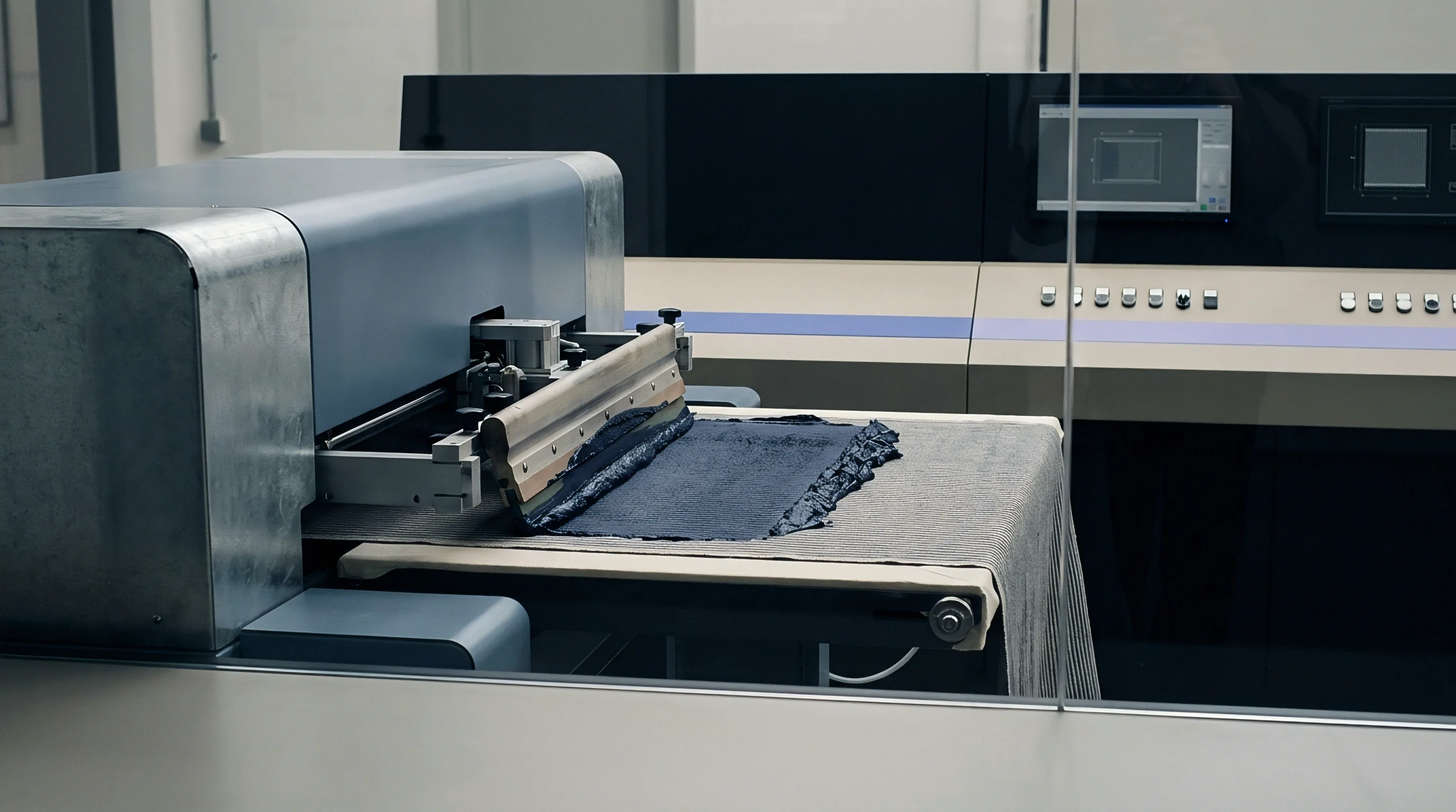

Rheology

Non-Newtonian Dynamic Response in High-Speed Web Applicators
Continuous textile and film coating lines deliver polymer compounds onto moving webs at line speeds ranging from 15 to 120 metres per minute. Fluid behavior within the narrow gap between an applicator blade, roll, or die lip and the flexible substrate determines initial wet film thickness, cross-web levelling, and penetration depth into the yarn bundles. Coating formulations based on waterborne polyurethane dispersions, solvent-borne acrylics, or liquid silicone rubbers exhibit pronounced non-Newtonian flow properties under processing conditions.
Shear rates within the coating zone regularly exceed 10,000 reciprocal seconds, driving structural changes in the fluid polymer network that alter apparent viscosity during application.
Pseudoplastic fluid systems undergo shear thinning inside high-shear application zones. Polymer chains align parallel to the direction of web travel, dropping hydraulic resistance and enabling smooth passage through clearances down to 20 micrometres. The fluid must recover its structural viscosity rapidly upon exiting the shearing geometry to arrest sag, strike-through, and edge bead migration.
Thixotropic fluids introduce a time-dependent structural collapse, where viscosity continues to decrease under sustained shear stress and rebounds over seconds or minutes once stress ceases. When recovery occurs too slowly, low-viscosity fluid migrates deep into the weave structure of high-filament polyamides or polyesters, consuming excessive chemical add-on without forming a continuous surface membrane.
| Application System | Shear Rate Range (s⁻¹) | Operational Viscosity (mPa·s) | Target Wet Add-on (g/m²) | Coat Weight Tolerance (g/m²) |
|---|---|---|---|---|
| Knife-over-Roll | 5,000 to 35,000 | 3,000 to 25,000 | 15 to 150 | ±2.5 |
| Slot Die Enclosed | 1,000 to 15,000 | 100 to 5,000 | 5 to 500 | ±0.5 |
| Direct Gravure | 10,000 to 80,000 | 50 to 1,500 | 2 to 25 | ±0.3 |
| Floating Knife (Air) | 2,000 to 12,000 | 8,000 to 45,000 | 20 to 200 | ±4.0 |
Yield Stress and Time-Dependent Structural Recovery
Formulations containing high solids loading or thickener additives display distinct yield stress values that resist initial flow until applied shear stress passes a critical threshold. Dilatant fluids present the opposite challenge, increasing apparent viscosity sharply under elevated shear rates. Dilatant spike events inside positive displacement pumps or narrow die feeds generate severe pressure surges, line stoppage risks, and mechanical wear on metering gears.
Dynamic viscosity measurements taken solely on benchtop rotational viscometers at low shear rates (0.1 to 100 reciprocal seconds) fail to capture fluid hydraulics under actual coating head conditions.
A high-solids polyurethane dispersion delivered at 40 metres per minute through a 50-micrometre blade gap experiences localized shear rates above 13,000 reciprocal seconds, dropping operational viscosity by up to 85 percent compared to static cup measurements.
Temperature fluctuations within chemical supply lines modify viscosity profiles during continuous production runs. Waterborne acrylic dispersions show viscosity shifts up to 3.5 percent per degree Celsius shift in fluid temperature. Uncontrolled thermal drift alters the hydraulic force generated against blade backs or inside slot die manifolds, shifting wet deposit weights across long manufacturing runs.
Heating jacket loops installed along chemical delivery hoses stabilize fluid supply temperatures within a narrow band of ±0.5 degrees Celsius, maintaining reproducible shear stress response across multi-shift production sequences.
Substrate porosity and surface energy interact directly with fluid rheology at the instant of contact. Filament spacing, yarn twist factor, and residual sizing agents on greige woven fabrics dictate capillary suction pressure according to the Washburn relationship. Higher capillary pressure draws low-viscosity liquid phases away from the coating film into the internal core of the fabric structure.
This selective phase separation leaves a high-solids filter cake at the surface, disrupting film formation and producing pinhole defects that ruin hydrostatic head performance.
Ignoring high-shear thixotropic breakdown causes excessive chemical penetration into structural yarns, stripping fabric flexibility and raising raw material consumption by up to 18 percent without improving surface barrier performance.

Head
Hydraulic Manifold Dynamics and Flow Distribution
Slot die coating heads rely on internal cavity geometry to convert a single pipe inlet stream into a uniform, planar fluid sheet across web widths exceeding 3.2 metres. The coat-hanger manifold profile balances fluid residence time and pressure drop across the width of the die. Fluid enters the central feed channel, splits along angled distribution arms, and exits through a tight, precision-ground land gap ranging from 100 to 750 micrometres.
Internal pressure drops across the distribution channel drive fluid laterally, compensating for viscous losses so that volumetric flow per unit width remains uniform from the center to the deckle edges.
Dimensional stability of the die lip gap under internal hydraulic pressure governs cross-web coat weight uniformity. High-viscosity compounds operating at internal die pressures between 3 and 15 bar exert expansion forces that deflect die lips if structural rigidity is insufficient. A local gap widening of 5 micrometres across a 200-micrometre nominal setting alters local volumetric discharge by up to 7.5 percent, driving cross-web coating weight variation out of specification limits.
Heavy-gauge stainless steel die bodies and internal pressure compensation bolts preserve gap tolerances under varying line throughput levels.

Boundary Layer Stabilization in Open and Enclosed Systems
Knife-over-roll applicators rely on dynamic pressure generation within the converging wedge formed between the blade edge and the backed web. Fluid dragged into the nip by web movement creates a high-pressure hydrodynamic wedge that lifts the blade or deflects the flexible substrate. The magnitude of this hydrodynamic force scales directly with web velocity, liquid viscosity, and blade profile geometry.
Beveled knife angles between 15 and 45 degrees produce controlled pressure profiles that meter the fluid film, whereas rounded or blunt knife profiles generate strong hydrodynamic lifting forces that create thick, uneven wet deposits.
- Hydrodynamic gap expansion forces the coating knife upward against mechanical position stops, increasing film thickness during line acceleration.
- Substrate deflection under wedge pressure compresses resilient backing rolls, causing edge-to-center coat weight gradients on wide textile lines.
- Fluid ribbing instabilities surface downstream of the application nip when capillary forces exceed surface tension forces at high capillary numbers.
- Air entrainment at the dynamic wetting line traps micro-bubbles under the wet film, creating pinhole voids upon passing through drying zones.
Modern continuous lines mitigate surface boundary air entrainment by installing vacuum backing boxes immediately upstream of the application point. Applying a controlled vacuum between 100 and 500 Pascals behind the moving web stabilizes the dynamic contact line, preventing air boundary layers from breaking into the fluid film at elevated line speeds. Substrate tension control must maintain uniform longitudinal tension within ±1.0 percent to prevent local bagginess or width contraction, which destabilizes hydraulic nip pressures across the application zone.
Enclosed applicator heads eliminate free fluid banks exposed to ambient plant air, minimizing solvent evaporation and skin formation during extended continuous runs. Pressurized applicator chambers supply formulation directly into doctor blade contacts under positive fluid pressure of 0.2 to 1.5 bar. Controlled positive pressure forces liquid into fabric surface contours, anchoring functional polyurethane or fluoropolymer coatings firmly onto open-weave structural fabrics without requiring high mechanical blade loading.
Coating machine suppliers often claim that wider blade clearances eliminate web break risks, yet this adjustment relies on mechanical tolerances to mask uncontrolled fluid pressure spikes inside open coater banks.


Metering

Coriolis Mass Flow Principles in Continuous Dosing Loops
Volumetric dosing methods using positive displacement gear or progressive cavity pumps suffer from drift when fluid density, temperature, or trapped air content varies during continuous operation. Mass flow dosing systems bypass fluid volume uncertainty by measuring mass flow directly using Coriolis force flowmeters installed inline. As liquid passes through vibrating sensor tubes within the meter, inertia induces a phase shift in tube oscillations proportional to the mass flow rate.
Coriolis sensors deliver real-time mass flow measurements accurate to within ±0.1 percent of actual flow, independent of fluid viscosity changes or non-Newtonian behavior.
Continuous closed-loop control systems match mass flow delivery directly to web line speed encoder signals. System controllers compute target mass delivery in kilograms per minute using web width, current line speed, and target dry coat weight combined with formulation solids content percentages. Variable frequency drives operating main dosing pumps adjust rotational speed in millisecond response cycles to correct flow deviations before coat weight errors manifest on the finished web.

How Does Coriolis Mass Feedback Correct Viscosity Swings?
Viscosity reductions caused by ambient warming or shear heating inside chemical supply lines cause conventional positive displacement pumps to experience slippage, reducing actual volumetric delivery despite constant shaft rotation. Coriolis mass flow controllers detect the resulting drop in mass throughput instantly. Controller algorithms ramp pump rotational frequency upward, restoring precise mass delivery to the coating head.
If fluid entrains air bubbles during chemical preparation or drum changeovers, volumetric meters report uncorrected pump delivery while actual polymer mass drops; Coriolis density measurement channels flag the density drop simultaneously, triggering dynamic stroke adjustment and alerting operators to de-aeration system failures.
- Verify zero-point stability on the inline Coriolis meter under full line pressure with downstream isolation valves fully closed.
- Input formulation specific gravity and measured total solids weight fraction into the central coat-weight control processor.
- Set target dry add-on weight in grams per square metre alongside active web coating width parameters.
- Engage auto-tracking feed mode to lock dosing pump drive response to primary line speed encoder signals.
- Monitor differential pressure across chemical filtration units upstream of the mass meter to prevent flow cavitation.
Consider a continuous coating line running a 1.8-metre wide technical polyester fabric at 35 metres per minute. The specification calls for a target dry polyurethane add-on weight of 45.0 grams per square metre using a liquid compound prepared at 52.0 percent total solids content by weight. The required dry mass delivery rate equals 3.645 kilograms per minute.
Accounting for the non-volatile solids fraction, the closed-loop Coriolis dosing system must deliver exactly 7.010 kilograms per minute of wet compound to the slot die applicator head. Should web speed accelerate to 42 metres per minute, the control system scales mass delivery upward to 8.412 kilograms per minute within 120 milliseconds, preserving coating weight precision across dynamic line transitions.
| Dosing Technology | Mass Flow Accuracy | Viscosity Shift Sensitivity | Air Entrainment Tolerance | Response Time |
|---|---|---|---|---|
| Coriolis Mass Meter + VFD Pump | ±0.10% | Immune | Measures & flags density drop | < 150 ms |
| Open-Loop Positive Displacement | ±2.50% | High (Slip increases) | Fails (Uncorrected volumetric error) | N/A (Open loop) |
| Pressure-Fed Volumetric Loop | ±1.20% | Moderate | Fails (Volumetric displacement) | 300 to 800 ms |
| Loss-in-Weight Tank System | ±0.50% | Immune | Insensitive to density change | 2,000 to 5,000 ms |
Under ISO 22810 hydrostatic pressure compliance audits for water-impermeable technical textiles, continuous coat weight variation exceeding ±1.5 grams per square metre across a production roll creates localized barrier failures that invalidate lot certification.
Does dynamic mass flow feedback fully prevent coating weight defect formation when micro-foaming lowers chemical compound density inside supply piping?

Shear

Polymer Degradation under High Hydraulic Shear
Passing structured polymer compounds through narrow clearances at elevated flow velocities subjects molecular chains to severe mechanical shear stress. High-molecular-weight polyurethanes, silicone elastomers, and specialized thickener matrices undergo mechanical scission when shear stress exceeds intermolecular bond strength. Polymer chain scission permanently lowers formulation viscosity, reduces tensile film strength, and degrades elasticity in cured coatings.
Mechanical degradation occurs heavily inside high-pressure positive displacement pumps, fine-mesh strainers, and high-velocity die feed channels.
Progressive cavity pumps and low-shear lobe pumps minimize polymer destruction compared to high-speed gear pumps. Multi-stage progressive cavity designs distribute pressure generation over multiple internal cavities, holding localized shear rates below 500 reciprocal seconds during delivery. Minimizing internal flow recirculation inside pressure relief bypass loops prevents repeated shear exposure of heat-sensitive or shear-vulnerable chemical dispersions.
Inline bypass lines should loop back to raw batch mixing vessels rather than short-circuiting directly into pump suction ports, allowing thermal dissipation before re-entering the dosing loop.
Thixotropic Breakdown and Cavitation Dynamics
Rapid acceleration of coating liquids through narrow pipe elbows or partially closed valve orifices drops local static pressure below the fluid vapor pressure. Cavitation bubbles form instantly in these low-pressure zones, collapsing violently upon entering downstream high-pressure regions. Cavitation shockwaves generate micro-jet erosion on stainless steel pump internals and release dissolved air micro-bubbles into the coating compound.
Entrained air bubbles forced through doctor blade nips expand inside drying ovens, creating microscopic pinhole networks that degrade moisture vapor barrier performance.
Matching pump internal clearances to compound shear sensitivity prevents mechanical polymer chain scission and eliminates downstream film pinholing.
Piping design for continuous chemical delivery lines mandates smooth internal bore finishes, generous bend radii (at least five times pipe internal diameter), and total elimination of sudden cross-sectional contractions. Suction piping sized to hold fluid velocity below 0.8 metres per second prevents Net Positive Suction Head available (NPSHa) from dropping below pump requirements. Discharge line velocities maintained between 1.2 and 2.0 metres per second prevent particle sedimentation of inorganic flame retardant or pigment additives without generating excessive line pressure drops.
- High-shear gear pump recirculation degrades synthetic thickeners, causing irreversible viscosity loss over four hours of continuous operation.
- Localized fluid cavitation at throttle valves entrains micro-air, generating pinholes that fail breathability and water barrier test standards.
- Abrupt internal pipe elbows create dead-water vortex zones where stagnant polyurethane compound gel particles form and break off into the web stream.
- Unjacketed feed lines allow wall-cooling effects that create thick peripheral gel layers, reducing effective hydraulic pipe diameter.
Viscoelastic fluids exhibit normal stress differences under high shear, generating rod-climbing behaviors (Weissenberg effect) inside open mixing tanks and coater feed banks. These normal stresses exert upward hydraulic forces against coating blades, pushing the mechanical assembly away from the backing roll and altering application thickness. Designing fluid delivery manifolds with tapered entry angles mitigates viscoelastic stress accumulation, maintaining predictable hydrodynamic forces at the point of application.
Low-shear chemical transport preserves formulation viscosity profiles, ensuring predictable leveling performance without demanding excess synthetic thickeners.


Verification

Online and Offline Coat Weight Validation
Verifying applied coating mass stability across web width and roll length requires combining continuous non-contact online sensors with standardized offline laboratory testing. Online measurement systems utilize beta backscatter, X-ray fluorescence, or near-infrared (NIR) absorption gauges mounted on scanning frames downstream of the application zone or drying oven. Scanning sensors traverse the web continuously, building high-resolution profile maps of gross product weight.
Subtracting real-time unwinding greige fabric mass signals measured upstream isolates net dry coat weight distribution across center, left, and right web zones.
Offline laboratory verification acts as the primary calibration standard for online scanning systems. Mass per unit area testing performed according to ISO 3801 involves cutting circular fabric swatches (typically 100 square centimetres) across the left, middle, and right sections of sample rolls. Chemical extraction methods or mass balance analysis before and after oven drying determine exact dry resin add-on.
Discrepancies between online scanner profiles and offline ISO 3801 test results indicate sensor calibration drift, air gap temperature distortion, or moisture content shifts within the base textile substrate.
| Performance Metric | Test Method Standard | Target Specification | Acceptable Tolerance Window | Hydraulic Failure Mechanism |
|---|---|---|---|---|
| Hydrostatic Head Pressure | ISO 811 | > 8,000 mm H₂O | -500 mm H₂O absolute minimum | Pinhole formation from cavitation bubbles |
| Tensile Strength (Grab Test) | ISO 13934-1 | 1,200 N / 50 mm | ±5.0% of nominal lot mean | Excess compound penetration stiffening yarns |
| Coating Adhesion Strength | ISO 2411 | > 45 N / 5 cm | -3.0 N / 5 cm single minimum | Insufficient hydraulic nip contact pressure |
| Water Vapor Permeability | BS 7209 / ASTM E96 | > 5,000 g/m²/24h | ±8.0% of target rating | Uncontrolled coat weight thickness variation |
Hydrostatic and Mechanical Performance Mapping
Barrier fabrics engineered for protective apparel or industrial containment must maintain minimum hydrostatic head resistance across every square metre of bulk production. ISO 811 testing applies increasing water pressure (60 centimetres H₂O per minute) to the coated surface until three water drops penetrate the film. Localized coat weight drops of as little as 3.0 grams per square metre below target specification cause premature water breakthrough, dropping hydrostatic head values from 10,000 millimetres to below 2,000 millimetres of water column.
Consistent hydraulic dosing guarantees uniform film thickness, eliminating weak spots that lead to bulk lot rejections.
Continuous scanning profile data demonstrates that cross-web coat weight variation must stay within ±1.2 grams per square metre to maintain ISO 811 hydrostatic compliance above 8,000 millimetres of water gauge.
Coating adhesion testing conducted per ISO 2411 measures the force required to peel the applied polymer membrane from the woven base structure. Insufficient fluid pressure inside enclosed applicator heads or excessively high compound viscosity prevents mechanical keying into yarn interstices, resulting in low peel strength values. Conversely, over-penetration caused by uncontrolled shear-thinning liquid behavior locks yarns together, reducing fabric tear strength measured under ISO 13937-2.
Dynamic dosing and hydraulic pressure management optimize the balance between surface film integrity and mechanical flexible strength.
Contractual supply agreements for technical military and medical fabrics mandate compliance with ISO 2411 coating adhesion limits, where any single roll sample yielding peel strength values below 40 Newtons per 5 centimetres results in immediate rejection of the entire 10,000-metre production batch.

Disbursement
Yield Optimization and Raw Material Cost Mechanics
Chemical raw materials constitute between 45 and 70 percent of total finished fabric manufacturing costs in specialized coating lines. High-performance polyurethane, fluoropolymer, and specialty silicone compounds command costs ranging from 4.50 to 28.00 USD per wet kilogram. Inprecise volumetric dosing systems that run coat weights above specification targets to ensure functional compliance waste chemical stock and erode converter operating margins.
Precision Coriolis mass flow dosing tightens add-on weight distribution bands, allowing technical managers to target minimum specification limits without breaching lower quality thresholds.
| Dosing Control Setup | Target Add-on (g/m²) | Process Variation (g/m²) | Operational Setpoint (g/m²) | Chemical Waste Cost per 100,000 m (USD) |
|---|---|---|---|---|
| Uncontrolled Manual Blade Gap | 40.0 | ±5.5 | 45.5 | 44,550 |
| Volumetric Pump Loop | 40.0 | ±2.5 | 42.5 | 20,250 |
| Coriolis Mass Closed Loop | 40.0 | ±0.6 | 40.6 | 4,860 |
Quantifying chemical yield savings on a continuous coating line operating at 1.8 metres fabric width over a 100,000-metre production run illustrates the financial return of mass flow controls. Assuming a target dry add-on weight of 40.0 grams per square metre and a chemical compound cost of 9.00 USD per dry kilogram, an open-loop system with a mass variation of ±5.5 grams per square metre requires setting the nominal target to 45.5 grams per square metre to prevent low-weight rejections. Implementing closed-loop Coriolis mass dosing reduces process variation to ±0.6 grams per square metre, enabling an operational setpoint of 40.6 grams per square metre.
This 4.9 gram per square metre add-on reduction saves 882 dry kilograms of polymer per 100,000 metres of production, yielding direct raw material cost savings of 7,938 USD per production run while cutting scrap rates by 3.2 percent.
Startup and changeover chemical losses represent another major cost driver in continuous lines. Traditional open-tank coater setups lose between 15 and 40 kilograms of mixed coating formulation during bath drainage and system flushing at color or compound changeovers. Enclosed slot die systems with low internal volume delivery piping reduce system dead-space liquid capacity to under 3.5 kilograms.
Automated solvent flush protocols clear internal flow paths within 90 seconds, reducing chemical waste disposal volume and shortening line turnaround times between custom customer lots.
Line speed optimization linked directly to mass flow delivery capacity increases total annual plant throughput. When fluid delivery loops adjust dynamically to real-time line speed acceleration without introducing coat weight lag, production managers run coating equipment at maximum drying capacity limits rather than holding speeds down to protect manual dosing stability. Increasing average operating speed from 25 to 38 metres per minute spreads fixed plant overhead costs across greater finished metre volume, reducing total conversion cost per square metre by up to 14 percent across annual operating schedules.