Optical Extensometry Edge Drift Mitigation for ISO 13936 Seam Displacement Analysis
Mitigate optical extensometry edge drift in ISO 13936 seam testing using collimated backlighting, telecentric lenses, and directional subpixel algorithms.

Fringe
Tensile testing of sewn textile seams according to ISO 13936 exposes a structural measurement vulnerability when video extensometers monitor yarn slippage. The standard evaluates yarn displacement parallel to the seam line under applied forces, targeting fixed opening thresholds of two millimeters or three millimeters. Standard mechanical crosshead indicators measure total specimen extension, which includes grip deformation and clamp seating.
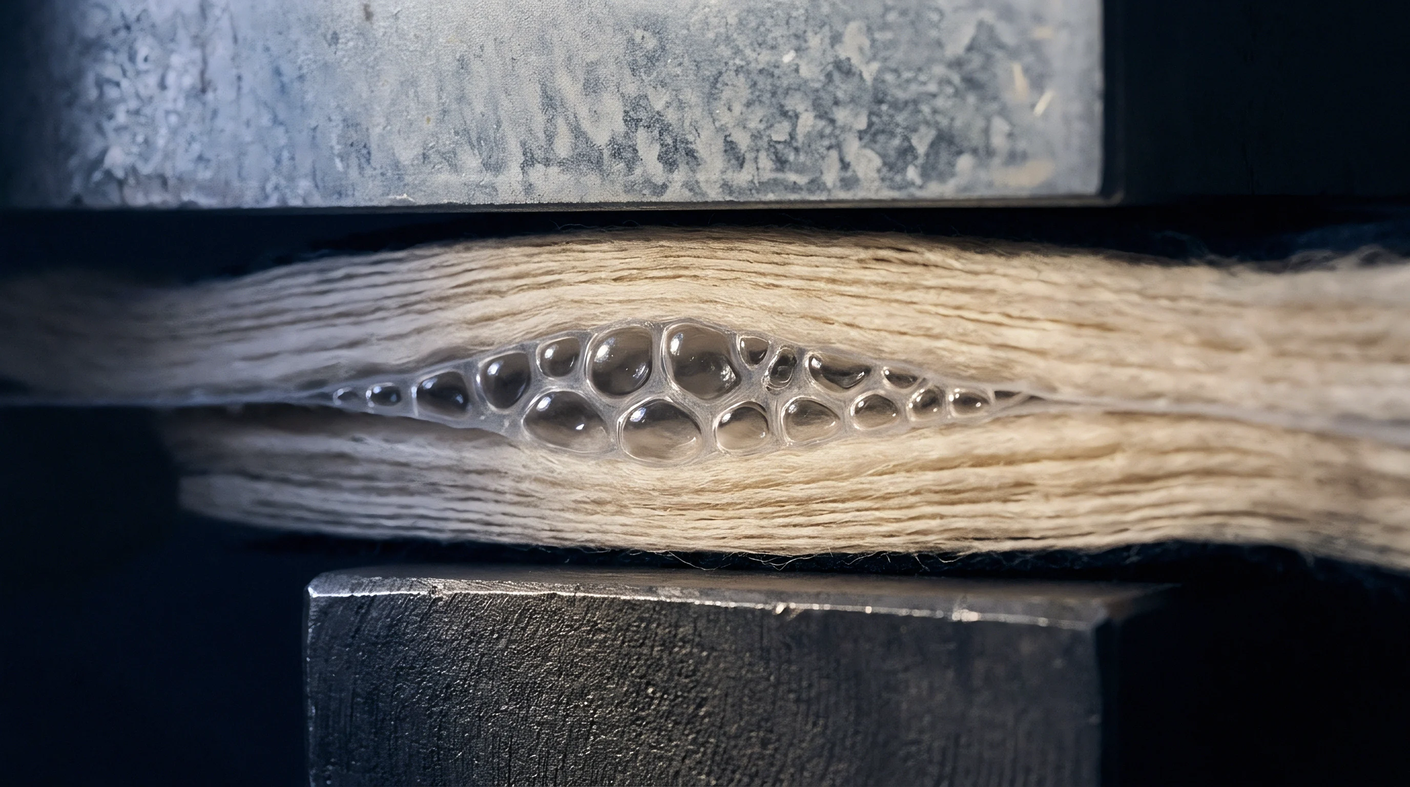
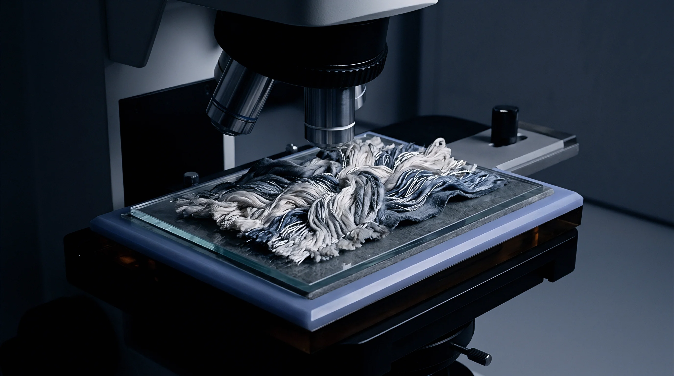
Video extensometers isolate the exact seam gap by tracking light intensity transitions across the stitch row. When tensile tension loads the orthogonal yarns, individual spun fibers release from the yarn bundle and protrude into the seam aperture. The camera detects this halo of loose filaments as solid textile boundary.
The load cell records tension continuously. As the stitch line pulls apart, loose fibers bloom into the void created by needle perforations. The edge-detection algorithm identifies this fuzzy boundary as yarn displacement, shifting the measured edge inward or outward depending on lighting contrast.
This shift represents edge drift. Edge drift generates false seam opening displacement readings before true inter-yarn slippage occurs. Standard testing programs fail compliant piece goods because the optical extensometer counts scattered surface hairs as structural seam separation.
Filament hairiness along the needle perforation creates a moving shadow boundary that obscures structural seam opening.
In wool blends, linen constructions, and textured filament upholstery substrates, yarn blooming accelerates rapidly between twenty newtons and sixty newtons of tensile pull. Needle penetration holes stretch under load. The camera registers three overlapping phenomena at the seam junction:
- Filament Bloom Displacement occurs when severed fibers unfurl into the needle gap and create false optical boundaries under direct tension.
- Decrimping Shadow Migration alters pixel grayscale values when warp yarns straighten and shift their cast shadows across adjacent weft crowns.
- Transverse Necking Contraction moves the specimen edge laterally across the camera field, skewing two-dimensional planar distance calculations.
Laboratory technicians often explain unexpected test failures by stating that the needle perforations simply yielded under tensile pull while the seam construction remained within commercial tolerances.
Optics
Camera positioning and lighting orientation govern spatial stability across the test plane. Standard laboratory configurations rely on front-mounted diffuse rings or overhead fluorescent arrays. These configurations illuminate surface hairiness, casting micro-shadows into the seam gap.
Glare blinds standard area-scan sensors. When yarn crowns rotate under tension, reflected highlights move across the surface. The optical tracking software mistakes moving highlights for structural yarn displacement.
Telecentric lenses coupled with collimated monochromatic backlighting eliminate this artifact by ignoring light rays that deviate from the optical axis.

Can Polarized Lighting Suppress Fiber Blur?
Cross-polarized illumination filters direct specular reflections from synthetic filaments without eliminating boundary contrast. Linear polarizing filters mounted across both light source and lens isolate the darker, structural yarn cores from translucent surface fibers. Translucent filaments scatter directed light.
Collimated backlighting cuts false shadows. When placed directly behind the clamped specimen, a high-intensity red light emitting diode panel projects crisp silhouettes of the warp and weft yarns onto the sensor. The camera captures yarn bundle bulk rather than protruding surface fibers.
Telecentric lenses preserve geometric scale when specimens neck inward under crosshead displacement.
Establishing an uncompromised optical path requires precise mechanical sequencing on the tensile bench:
- Align the telecentric lens perpendicular to the clamped seam line within zero point two degrees of plane parallelism.
- Mount a red collimated backlight behind the specimen, setting irradiance to saturate camera pixels in open seam gaps without blooming adjacent boundaries.
- Position cross-polarized linear filters over auxiliary front lights to extinguish specular reflections from polyester or nylon sewing yarns.
- Lock the aperture at f-eight to establish sufficient depth of field across out-of-plane yarn rotation during crosshead pull.
- Verify spatial calibration across the full fifty-millimeter field using a certified glass target before clamping the textile specimen.
Parallel rays through telecentric lenses ensure true scale across varying specimen depths.
Gradient
Subpixel edge algorithms establish the digital seam boundary by evaluating intensity slopes across neighboring pixel arrays. A simple grayscale threshold fails on textile substrates because yarn porosity generates gradual, stepped transitions rather than sharp step functions. Edge detection algorithms evaluate first-order intensity derivatives.
The peak of this derivative marks the physical yarn boundary. When surface fuzz drifts into the gap, the intensity slope flattens, dispersing the mathematical derivative across five to fifteen pixels. The raw pixel coordinate shifts.
Contrast drops across dyed filaments. Edge drift mitigation requires directionally constrained edge operators. Because ISO 13936 measures displacement perpendicular to the stitch row, mathematical kernels must scan strictly along the axis of tensile loading.
Evaluating intensity gradients across orthogonal axes introduces irrelevant fiber hairiness into the displacement calculation. Algorithms that enforce parabolic profile interpolation locate zero-crossings of the second derivative, achieving subpixel resolution down to zero point zero two millimeters.
Edge extraction in high-magnification textile metrology shares mathematical models with satellite orbital imagery and microelectronic wafer manufacturing, where atmospheric dust or photoresist bleed creates boundary ambiguity across subpixel targets. In textile analysis, these models isolate the structural yarn mass from wandering single filaments.
Subpixel edge interpolation limits seam opening tracking error to 0.04 millimeters when backlighting contrast exceeds thirty gray levels.
Tracking algorithms must monitor multiple yarn crowns across a broad region of interest rather than relying on a single tracking point. Averaging suppresses local yarn distortion. When a single filament snaps or protrudes, multi-point spatial averaging across twenty millimeters of the stitch row prevents localized fiber bloom from distorting the seam opening value.
| Tracking Algorithm | Optical Configuration | Measured Opening (mm) | Caliper Ground Truth (mm) | Edge Drift Bias (mm) |
|---|---|---|---|---|
| Fixed Grayscale Threshold | Diffuse Front Ring | 2.68 | 2.14 | +0.54 |
| Standard Sobel Operator | Diffuse Front Ring | 2.46 | 2.14 | +0.32 |
| Directional Derivative Filter | Cross-Polarized Front | 2.28 | 2.14 | +0.14 |
| Parabolic Subpixel Interpolation | Collimated Red Backlight | 2.16 | 2.14 | +0.02 |
| Multi-Crown Centroid Spatial Average | Collimated Red Backlight | 2.14 | 2.14 | 0.00 |
Whether algorithm developers can train generalized machine vision models to distinguish loose filament blooming across all variable weave floats remains unsettled in textile metrology circles.
Gauge
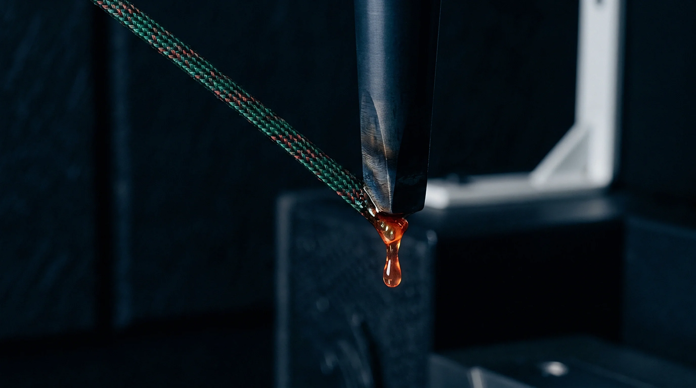
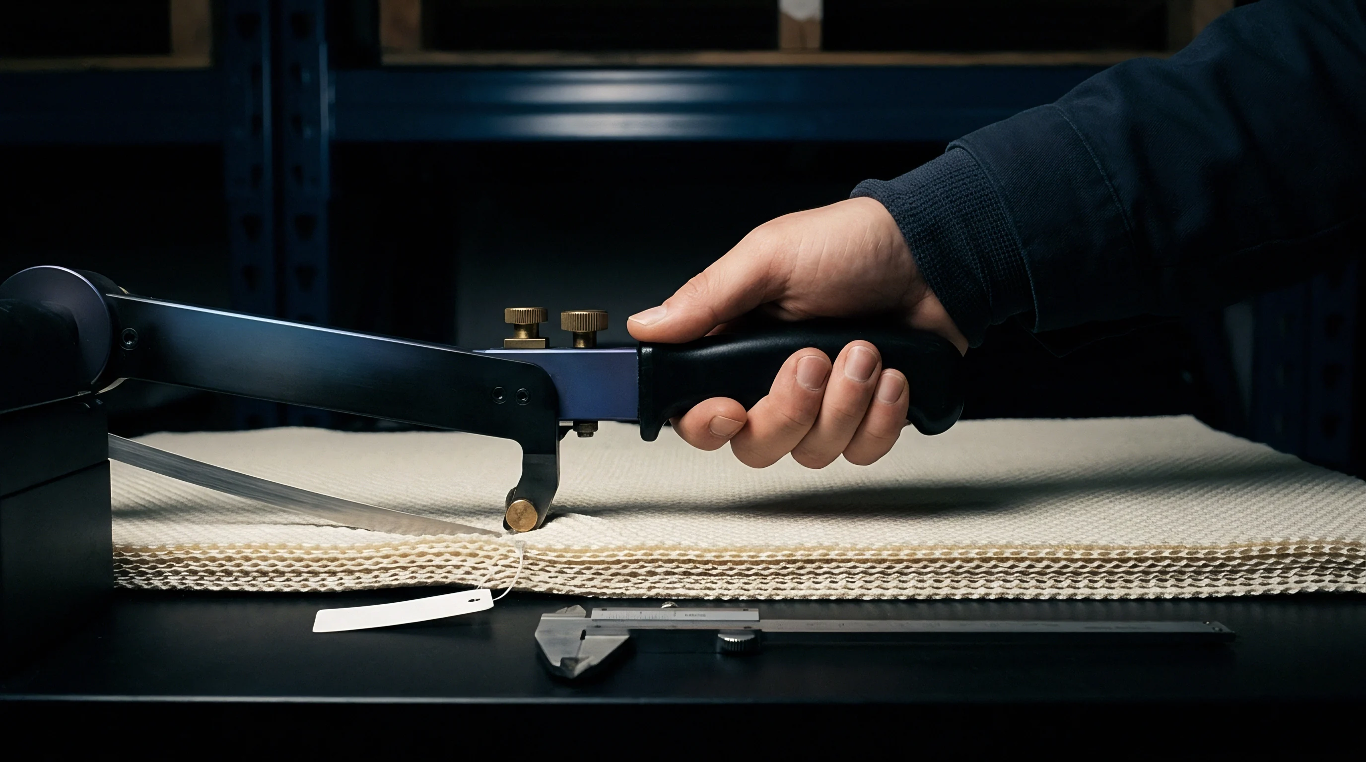
Discrepancies between mechanical feeler blades and contact-free video records originate from how physical tools interact with deformed yarn bundles. Under ISO 13936-1, an opening of two millimeters under an applied load between twenty and two hundred newtons defines the boundary between acceptance and rejection for apparel and upholstery fabrics. When an operator inserts a tapered mechanical thickness blade into a parted seam under load, the blade physically pushes loose surface filaments aside, registering the gap between structural yarn cores.
Manual feeler gauges compress loose yarns.

Will Edge Drift Trigger False Rejections under Audit?
Commercial contracts reject two-millimeter openings. An optical system without edge drift filtering records fiber fuzz as solid yarn boundary, declaring that the seam opened two millimeters when structural core slippage reached only one point six millimeters. The test report records a false failure.
Conversely, if edge filtering overcompensates by eroding edge pixels, true structural yarn slippage goes undetected, generating a false pass. Retail brand audits penalize both outcomes.
| Textile Classification | Yarn Composition | Standard Limit Under ISO 13936 | Observed Optical Drift (mm) | Commercial Decision Impact |
|---|---|---|---|---|
| Apparel Worsted Suiting | 100% Wool, 210 g/m² | Max 2.0 mm at 100 N | 0.35 to 0.48 | False rejection without backlighting |
| Commercial Upholstery | 100% Textured Polyester | Max 3.0 mm at 180 N | 0.25 to 0.40 | Borderline batch dispute |
| Workwear Drill | 65/35 Poly-Cotton, 280 g/m² | Max 2.0 mm at 120 N | 0.15 to 0.28 | False failure during brand audit |
| Filament Lining Taffeta | 100% Viscose, 85 g/m² | Max 2.0 mm at 60 N | 0.08 to 0.14 | Conformity maintained |
When preparing verification dossiers for accredited certification bodies, laboratories must substantiate optical extensometer calibration. Compliance files maintain validity when specific records accompany every test report:
- Spatial Grid Calibration Certificates establishing sub-pixel dimensional accuracy across the active field of view using certified stage micrometers.
- Backlighting Contrast Histograms validating a minimum separation of thirty grayscale levels between yarn bulk and open seam void.
- Algorithm Configuration Parameters specifying directional derivative kernels and spatial averaging window widths.
- Comparative Feeler Gauge Benchmarks confirming alignment between manual mechanical insertion and automated optical metrics within zero point zero five millimeters.
ISO 17025 accreditation clauses mandate documented verification of measurement uncertainty for all automated optical sensors before test laboratories issue valid conformity certificates.

Recourse
When test houses issue failing test reports based on unmitigated yarn fuzz drift, financial penalties land on the garment manufacturer. The testing laboratory absorbs no liability. Disputed lots stall at customs.
Importers absorb the delay. Commercial contracts stipulate immediate stop-shipment orders or steep discounts when an accredited laboratory records a seam opening exceeding two millimeters under ISO 13936-1. The financial fallout extends beyond laboratory fees.
Consider an operational scenario constructed with declared assumptions: take a production lot of 10,000 meters of polyester-viscose suiting cloth priced at 6.20 dollars per meter, tested under ISO 13936-1 Part 1 at a 100 newton target load for a 2.0 millimeter maximum opening. Assume an unmitigated video extensometer registers edge drift of 0.45 millimeters caused by loose staple fiber halos. The instrument reports a seam displacement of 2.30 millimeters, failing the specification.
The brand issues an immediate chargeback of thirty percent against the invoice value, totaling 18,600 dollars, while demanding an independent arbitration test.
Retesting costs accumulate rapidly. Retesting costs four hundred dollars per swatch. Air-freighting replacement swatches to a secondary accredited facility adds twelve hundred dollars.
Port storage demurrage on the stranded container accrues at two hundred fifty dollars per calendar day during the eighteen-day dispute window, generating 4,500 dollars in port expenses. When secondary testing with collimated backlighting and subpixel centroid filtering demonstrates an actual seam opening of only 1.85 millimeters, the batch passes. The manufacturer recovers the invoice price, but absorbing demurrage and secondary laboratory fees reduces operating margin across the production run by 6,100 dollars.
Failure to document optical drift calibration in ISO 17025 test dossiers shifts border rejection expenses directly onto the garment vendor under standard retail vendor agreements.
Sourcing agreements govern these disputes through testing clauses. Buyers write chargebacks into purchase orders. Fabric suppliers protect export margins by embedding optical test criteria into technical specifications, stipulating that video extensometry records must include backlighting and subpixel drift mitigation to serve as valid grounds for batch rejection.
Failure to specify optical extensometer filtration criteria in purchase orders leaves suppliers exposed to catastrophic chargebacks whenever automated laboratory cameras confuse surface fiber fuzz with structural seam slippage.