Standard Tensile Machine Calibration Procedures in Textile Seam Testing
Calibration of tensile testing machines for seam strength requires verified load accuracy under ISO 7500-1 and frame compliance corrections to avoid test errors.
Load
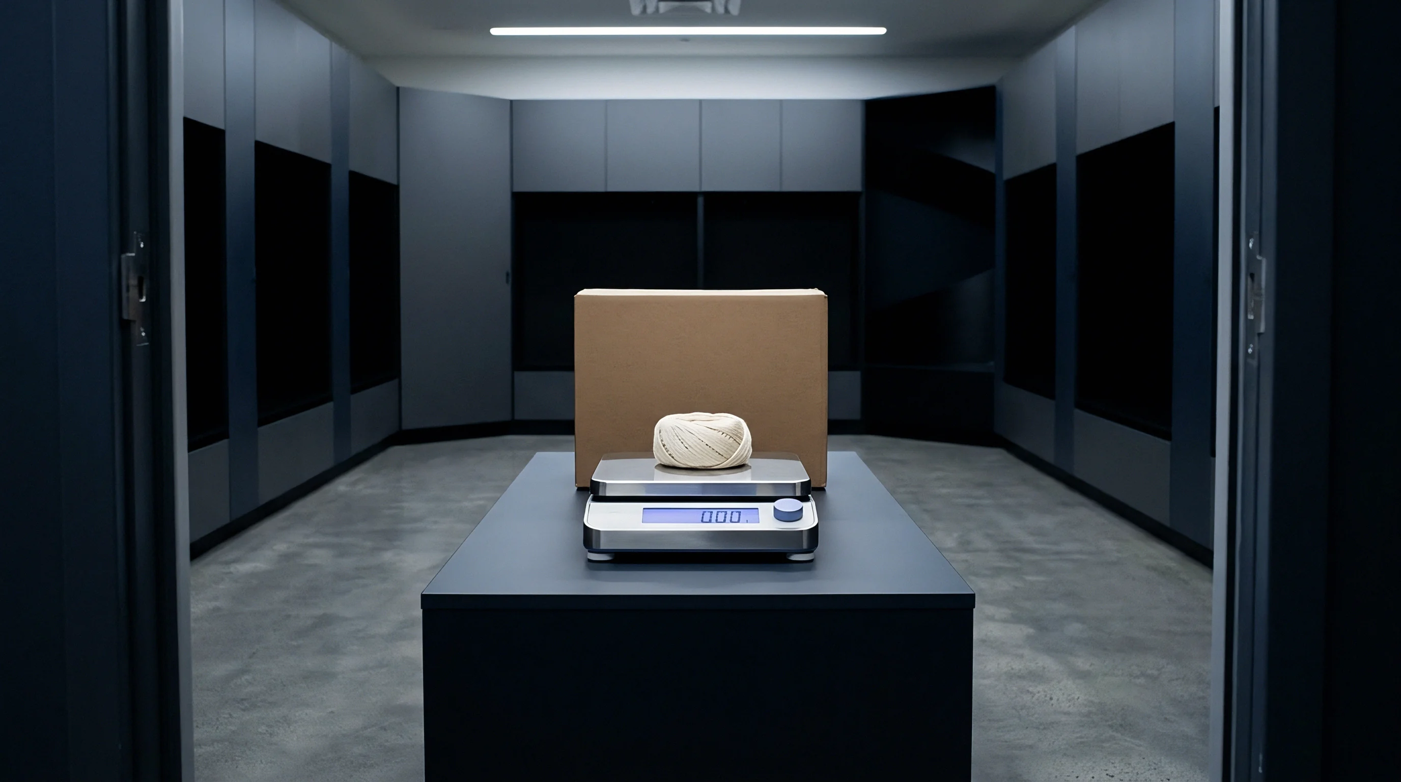
Force transducer accuracy determines whether a laboratory correctly measures maximum seam strength under ISO 13935-1 or ASTM D1683. Universal testing instruments utilize strain-gauge transducers that require periodic verification against secondary standards certified under ISO 7500-1 or ASTM E4. Force measurement drives seam compliance.
In textile seam evaluation, small errors in load cell output lead to false failures of high-value tailored garments or unearned acceptance of defective structural seams. Testing laboratories that operate unverified load cells compromise every seam rupture figure reported on commercial test dossiers.
Transducer Verification Intervals
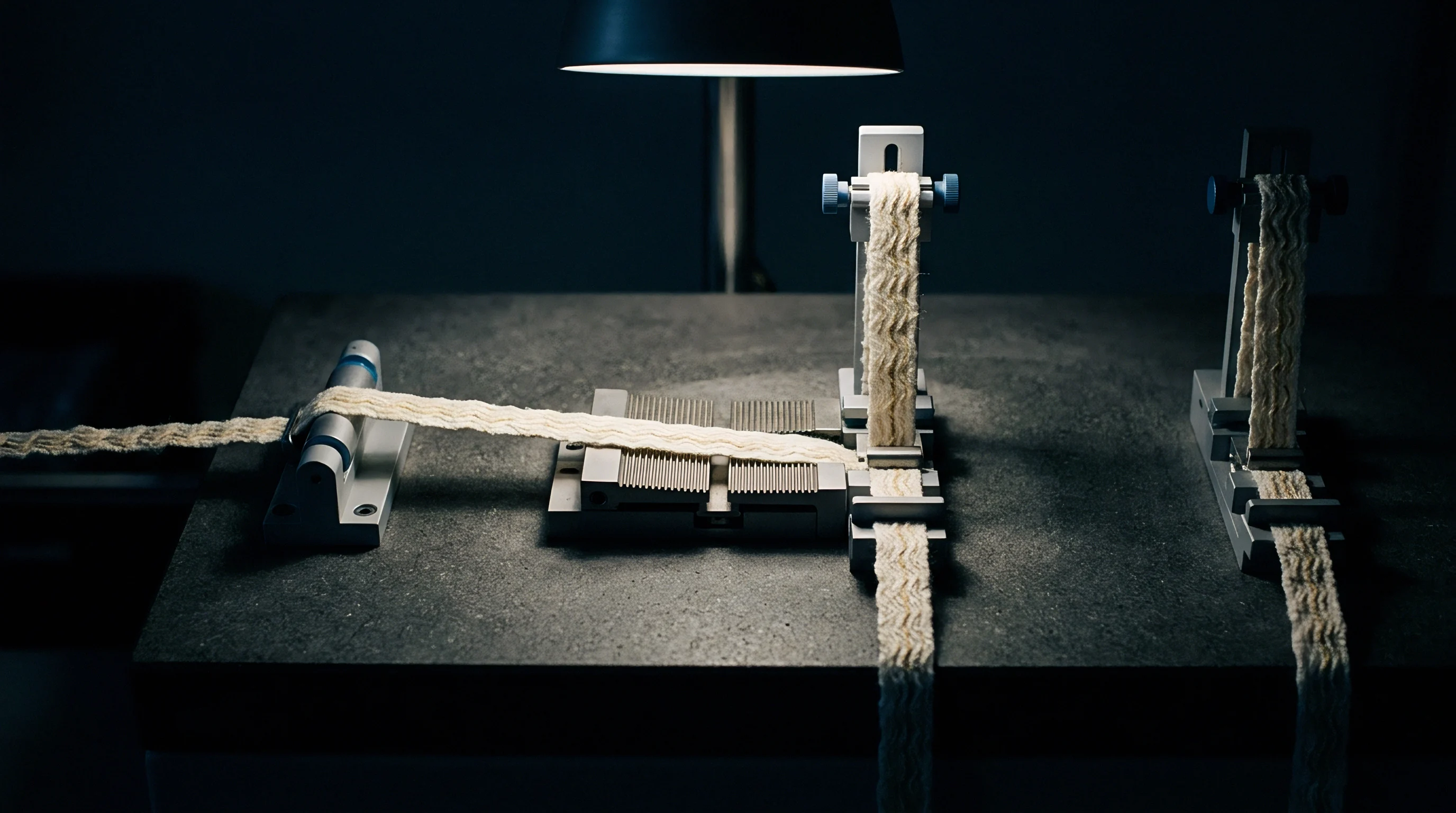
Calibration technicians apply certified dead weights or secondary reference cells across the working force envelope of the frame. Verification covers five to ten ascending and descending force increments to evaluate linearity, repeatability, and zero return. Standard laboratory practice dictates a twelve-month calibration interval, but high-throughput mills conducting hundreds of ISO 13935-2 grab tests weekly experience transducer drift far sooner.
Force cells operating near their lower limits exhibit significant proportional error. When evaluating light woven fabrics with seam strength requirements near fifty newtons, using a five-kilonewton load cell without low-range verification introduces unacceptable measurement bias.
Machine tare masks physical noise. Transducer tare procedures must zero out the physical weight of heavy pneumatic grips before starting a test sequence. Failing to account for clamp weight strains the load cell bridge before specimen mounting, shifting the operating baseline into a non-linear voltage region.
A class 0.5 force transducer operating below one percent of full scale capacity exhibits relative error exceeding two percent during low-force seam slippage evaluation.
Proving Instruments and Transfer Uncertainty
Secondary reference devices require traceable calibration through national metrology institutes every twelve months. Transfer standards used to calibrate textile testing frames include proving rings or precision reference load cells with an uncertainty budget five times smaller than the machine under test. The calibration process records force values across multiple runs to calculate relative indication error and relative repeatability error.
| Calibration Standard | Accuracy Class | Indication Error Limit (%) | Repeatability Error Limit (%) | Zero Return Error (%) |
|---|---|---|---|---|
| ISO 7500-1 | Class 0.5 | ±0.50 | 0.50 | ±0.10 |
| ISO 7500-1 | Class 1.0 | ±1.00 | 1.00 | ±0.20 |
| ASTM E4 | Standard Pass | ±1.00 | 1.00 | ±0.25 |
| ISO 7500-1 | Class 2.0 | ±2.00 | 2.00 | ±0.40 |
Inaccurate force transducers distort seam load-extension curves, causing verified thread breakage limits to appear sub-standard and triggering unwarranted fabric lot rejections that cost garment converters tens of thousands of dollars in delayed shipments.
- Zero-point drift ~ Thermal fluctuations inside the strain gauge bridge shift the baseline force reading during long testing cycles.
- Non-linearity at low forces ~ Calibration performed exclusively at upper load cell limits leaves force readings below ten newtons unverified during seam slippage initiation.
- Hysteresis accumulation ~ Mechanical hysteresis in older load cell flexures creates divergent tension curves between ascending and descending force application.
- Off-center load application ~ Misaligned pneumatic grips impart eccentric force components that distort strain gauge voltage outputs during seam pull tests.
Speed
Constant rate of extension testing relies on precise crosshead displacement rates to produce repeatable seam rupture data under ISO 13935-2. Textile materials exhibit viscoelastic behavior, meaning that thread tensile resistance and fabric seam opening forces vary directly with strain rate. A machine running five percent faster than specified applies higher strain rates to the seam assembly, artificiality inflating measured peak force at rupture.
Crosshead Displacement and Velocity Rules
Linear motion transducers quantify physical traverse along the vertical columns during tensile deformation. Calibration procedures under ASTM E2658 verify crosshead velocity accuracy across specified speeds, typically fifty millimeters per minute for ISO 13935-1 strip tests and fifty or one hundred millimeters per minute for ASTM D1683 seam slippage tests. Crosshead speed alters woven response.
Technicians use optical encoders or dial indicators combined with precision electronic timers to record actual crosshead displacement over timed intervals.
- Affix a calibrated optical encoder or linear variable differential transformer to the moving crosshead assembly.
- Set the machine control software to execute a constant rate of extension traverse over a distance of one hundred millimeters.
- Record time elapsed using a certified digital timer with precision of zero point zero zero one seconds.
- Compare measured displacement against digital transducer readouts at five equidistant points along the travel stroke.
- Calculate velocity percentage error and adjust motor drive compensation parameters when deviation exceeds zero point five percent.

Extensometer Calibration and Gage Length Accuracy
Direct strain measurement devices override frame flexure by tracking optical markers attached to the fabric specimen. Gage length accuracy forms the foundation of strain calculations in seam opening and elongation tests. Extensometers eliminate frame deflection.
ASTM E2309 governs displacement calibration for tensile test equipment, setting maximum allowable error at zero point five percent of reading or zero point one millimeter, whichever is smaller.
Systematic crosshead velocity variation alters textile viscoelastic damping and invalidates comparative seam slippage measurements between testing facilities.
| Standard Method | Nominal Velocity (mm/min) | Velocity Tolerance (%) | Gage Length (mm) | Gage Length Tolerance (mm) |
|---|---|---|---|---|
| ISO 13935-1 (Strip) | 100.0 | ±10.0 | 200.0 | ±1.0 |
| ISO 13935-2 (Grab) | 50.0 | ±10.0 | 100.0 | ±1.0 |
| ASTM D1683 (Seam) | 50.0 | ±2.0 | 75.0 | ±0.5 |
| ASTM D5034 (Grab) | 300.0 | ±10.0 | 75.0 | ±1.0 |
Instrument manufacturers frequently claim that digital motor encoders eliminate the need for physical speed verification, arguing that internal drive feedback loops automatically guarantee perfect crosshead motion regardless of mechanical wear or lead screw contamination.

Jaw
Clamping mechanisms hold the fabric swatch securely without causing local yarn damage or permitting specimen pull-out during tension application. In seam testing, jaw face condition and alignment exert direct control over failure location. A jaw-break failure occurs when high local clamping pressure damages yarn structure at the grip line, yielding an artificially low breaking strength reading that reflects clamp geometry rather than seam integrity.
Clamping Alignment and Face Friction Dynamics
Parallel contact surfaces prevent stress concentration along the specimen edge during ISO 13935-1 seam pulls. Misaligned jaw faces pinch fabric unevenly, concentrating tensile load on one side of the seam swatch and causing premature sequential thread failure. Grip jaw face friction varies.
Calibration verifies face parallelism under full clamping force using pressure-sensitive film or micrometer readings taken across four contact quadrants.
Clamping stress degrades seam threads. Rubber-faced, serrated, or wave-profile jaw inserts require periodic durometer and surface profile verification. Worn rubber inserts allow fabric slippage during high-tension pulls, producing false extension peaks on the load-elongation curve.
Serrated jaws with excessive sharpness cut filament yarns at low force thresholds.
- Parallelism check ~ Measure contact gap between upper and lower jaw faces using feeler gauges across the full clamp width before testing seam swatches.
- Rubber insert durometer testing ~ Verify face hardness remains between sixty and seventy Shore A to prevent thread crushing or fabric slippage.
- Pressure transducer cross-verification ~ Insert a thin film pressure sensor between closed jaws to confirm uniform clamping force distribution across the specimen face.
- Slippage line tracking ~ Paint reference lines on specimen fabrics at the clamp edge to identify micro-slippage during high tension seam pulls.

Pneumatic Clamping Force Uniformity
Regulated air pressure lines supply pneumatic actuators to deliver constant lateral force against the specimen. Pneumatic pressure drops cause slip. Calibration of pneumatic clamping systems involves verifying pressure gauge accuracy against a certified master gauge and confirming that line pressure remains stable during rapid crosshead displacement.
Inconsistent air pressure leads to variable clamping force, introducing uncontrolled specimen slip during seam slippage determinations under ASTM D1683.
Uncalibrated clamping pressure leads directly to invalid jaw-line fabric breaks that skew ISO 13935 seam strength distribution statistics.
Do dynamic pressure drops inside laboratory air lines during simultaneous multi-frame operation introduce unaccounted jaw slippage during peak seam pull forces?
Compliance
Structural deformation within the testing frame distorts measured fabric elongation during high-load seam rupture tests. When a tensile machine pulls a heavy seam construction, force acts equally on the fabric specimen, load cell, drive screws, crosshead, and jaw adapters. Every metallic component undergoes micro-elastic strain.
Without software-based frame compliance correction, total crosshead displacement represents fabric extension combined with mechanical frame flexure.
Is Frame Deflection Distorting High Force Seam Elongation Figures?
Uncompensated elastic extension inside load cells, drive screws, and jaw mounts shifts the apparent load-displacement curve toward higher strain values. Frame stiffness alters breaking energy. In seam slippage evaluations where six-millimeter thread displacement force is recorded, frame flexure introduces substantial error.
A testing machine with a system stiffness of twenty kilonewtons per millimeter yields zero point zero five millimeters of frame deflection under a one-kilonewton load, which equals nearly one percent error on narrow gage length tests.
System compliance shifts force curves. Calibration engineers establish machine compliance matrices by loading a high-rigidity solid steel bar in place of a fabric specimen. The resulting force-displacement curve represents pure mechanical frame deformation.
Modern machine control software stores this calibration curve and subtracts frame deflection from crosshead displacement in real time during seam testing.
System Stiffness and Tare Correction Procedures
A rigid steel calibration specimen allows technicians to measure baseline machine displacement under load without fabric extension. Mathematical subtraction of machine flexure produces true specimen extension. Consider a seam strength test where a structural heavy canvas seam generates eight hundred newtons of peak tension before breaking.
Uncorrected crosshead travel records three point two zero millimeters of total displacement. Frame compliance calibration shows that the machine assembly deflects zero point four zero millimeters at eight hundred newtons force.
True specimen elongation calculates as three point two zero millimeters minus zero point four zero millimeters, resulting in two point eight zero millimeters actual seam extension. The uncorrected measurement overstates seam extension by fourteen point three percent. This magnitude of error causes high-modulus technical seams to fail elongation specifications defined in brand quality guidelines.
Frame compliance compensation converts raw crosshead displacement into true specimen strain by mathematically removing elastic machine deformation.
ISO 13935-1 Clause 8.2 specifies that extension measurements must account for instrument compliance when testing low-strain seam constructions or when using non-extensometric displacement logging.

Audit
Calibration documentation establishes legal and commercial validity for seam strength test reports submitted to buyers. An unaccredited calibration or an incomplete certificate creates legal vulnerabilities during brand audits and customs disputes. Traceability chains demand intact records.
The ISO/IEC 17025 standard requires testing laboratories to maintain an unbroken, documented chain of traceable calibrations connecting their working machines to primary national measurement standards.
Calibration Certificate Verification and ISO/IEC 17025 Scope
Technical compliance reviews begin by examining the scope of accreditation issued to the metrology service laboratory. A calibration provider accredited for general force calibration under ISO 7500-1 may lack accreditation for displacement verification under ASTM E2309 or crosshead speed verification under ASTM E2658. Expired certificates void batch releases.
Audit trails protect brand liability. Calibration certificates must explicitly state measurement uncertainty values, coverage factors, environmental testing conditions, and traceable reference standards utilized.
| Uncertainty Source | Distribution Type | Standard Uncertainty Contribution | Sensitivity Coefficient |
|---|---|---|---|
| Reference Load Cell Traceability | Normal | u_ref = 0.12% | 1.0 |
| Force Transducer Non-Linearity | Rectangular | u_nl = 0.15% | 1.0 |
| Crosshead Velocity Drift | Rectangular | u_vel = 0.20% | 0.5 |
| System Compliance Deviation | Normal | u_comp = 0.08 mm | 1.2 |
| Ambient Temperature Drift | Rectangular | u_temp = 0.05% | 0.3 |
Uncertainty Budget Elements for Seam Strength Methods
Combined standard uncertainty calculations aggregate contributions from force transducers, extensometers, and ambient laboratory conditions. Uncertainty budgets expand total error. The combined expanded uncertainty multiplied by a coverage factor of k=2 establishes a ninety-five percent confidence interval for reported seam strength results.
When reported test results fall within the uncertainty guardband near a buyer specification limit, the laboratory cannot confirm conformity without risking false acceptance.
- Accreditation scope documentation ~ Confirm the calibration provider holds ISO/IEC 17025 accreditation explicitly covering ISO 7500-1 and ASTM E2309 methods.
- Traceability certificate chain ~ Retain calibration reports for transfer proving devices showing direct measurement traceability to national metrology standards.
- Expanded uncertainty statements ~ Ensure calibration certificates detail coverage factors and expanded uncertainty figures for every verified load point.
- Environmental log records ~ Maintain continuous temperature and humidity logs during machine calibration to validate atmospheric stability requirements.
As a rule of thumb, when the expanded calibration uncertainty of a tensile frame exceeds one-third of the specification tolerance band for seam strength, the instrument cannot reliably adjudicate product pass-fail decisions.

Ledger
Commercial exposure arises when uncalibrated tensile testing leads to false acceptance or false rejection of production fabric lots. In global textile supply chains, brand owners specify minimum seam strength parameters to guarantee garment durability and safety. Lab error risks customs clearance.
When a garment factory ships thirty thousand units of woven outerwear based on internal test reports generated by unverified tensile equipment, the financial risk remains fully attached to the factory invoice.
Retest Risk and Border Dispute Arithmetic
Border detentions triggered by conflicting seam strength test results impose immediate demurrage fees and laboratory retest charges on importers. If a buyer compliance lab re-tests incoming garments and finds seam failure under ISO 13935-2 due to machine calibration discrepancies at the origin mill, the buyer issues a full commercial claim. Consider a shipment of thirty thousand jackets with an invoice value of thirty dollars per unit, totaling nine hundred thousand dollars.
The buyer retests ten swatches at a certified destination laboratory and records an average seam strength of one hundred and forty newtons against a required contract threshold of one hundred and sixty newtons.
Origin mill test records showed an average seam strength of one hundred and sixty-eight newtons. Investigation reveals the origin mill tensile tester operated with a three-year-old load cell calibration exhibiting a negative force bias of six percent, combined with uncalibrated crosshead speed running twelve percent too fast. The destination lab used an ISO 7500-1 Class 0.5 verified frame.
The destination lab results stand. The buyer rejects the entire nine-hundred-thousand-dollar container, imposing administrative retest penalties of four thousand five hundred dollars and charging return freight expenses to the supplier.

Contractual Allocation of Calibration Failures
Purchase orders incorporating clear testing governance terms reallocate testing dispute costs to the mill when instrument drift causes non-conformity. Smart sourcing practices enforce clauses requiring suppliers to furnish ISO/IEC 17025 calibration dossiers for all tensile equipment before production sign-off. When origin calibration data fails verification, contract penalties execute automatically, deducting re-inspection costs, container detention fees, and airfreight charges from open vendor balances.
Contract clauses that define instrument calibration standards create explicit financial accountability. Specifying ISO 7500-1 Class 0.5 accuracy and mandatory system compliance logging inside purchase order quality terms protects buyers against origin lab drift. When origin laboratories maintain rigorous, audited calibration schedules, tensile data holds up under cross-border audits, protecting shipment clearance and stabilizing global textile trade relationships.