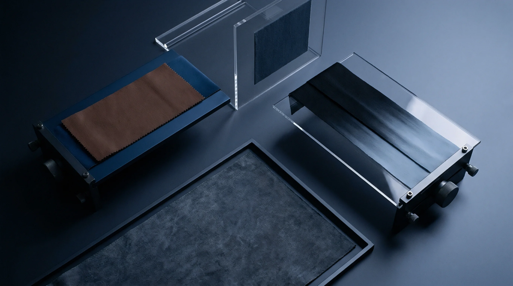
Tensile Measurement
Mechanical displacement per unit of time defines the constant movement of a test frame crosshead during destructive material evaluation of textile filaments or composite yarns. This crosshead speed governs the strain rate applied to a specimen held between stationary and moving grips. Laboratories utilize this parameter to standardize the extension conditions required for consistent stress strain curves.
Calibration of the equipment ensures the distance traveled remains uniform throughout the duration of the pull. Discrepancies in motor response or gear backlash alter the actual rate of elongation, which distorts the modulus calculation. Testing protocols dictate precise settings for specific fibre types to prevent premature failure.
Operational Variance
Variations in setting the rate affect the detected ultimate tensile strength of high tenacity aramid or polyethylene fibres. Higher velocities generate rapid load accumulation, which frequently masks the ductile behavior of thermoplastic polymers. Lower settings permit molecular relaxation during the stretching cycle, providing a clearer view of the elastic limit.
Technicians adjust the feed rate based on the estimated break elongation of the sample batch. A slow pull allows the sensor array to capture granular data points near the yield point. High speeds increase the likelihood of grip slippage due to the sudden impact force transferred through the clamp interfaces.
Calibration Requirement
Precise control of the drive motor prevents measurement error during high volume production inspections. Load cells record the force resistance as the actuator travels the measured vertical distance. Regular verification of the displacement sensors maintains alignment with industry quality standards for yarn durability.
Digital control units regulate the electrical current to maintain a steady cadence against internal mechanical resistance. Friction within the lead screw assembly changes over time, requiring periodic adjustment of the drive compensation. If the controller fails to maintain the programmed rate, the raw data gathered during the break test loses its reliability for batch verification.
Mechanical Constraint
Limiting the travel rate prevents damage to delicate force transducers during unintended sample ruptures. Sudden energy release upon fiber breakage transmits a shockwave that travels up the frame toward the load cell housing. Dampening the transition from tension to zero load protects the instrument from mechanical fatigue over extended operational cycles.
Excessive velocity settings increase the risk of harmonic vibration in the frame members, which introduces noise into the captured signal. Correct synchronization between the encoder and the data acquisition software remains the primary factor for ensuring the integrity of the reported elongation percentage. Consistent performance rests upon the rigid management of motor output against the measured resistance of the textile sample.