Resolving Structural Discrepancies between ASTM and GB Seam Slippage Test Calibration Methods
Resolving seam slippage discrepancies between ASTM and GB protocols demands harmonizing pretension baselines and jaw surface compliance before curve subtraction.

Mechanics
Tensile testing frames at origin and destination facilities often produce conflicting seam movement numbers for identical fabric constructions. A 280 g/m² woven polyester-viscose suiting fabric clearing ASTM D4034 at 100 N with a recorded 4.2 mm opening frequently records a 6.8 mm opening under GB/T 13772.1 at that same nominal force. The gap comes down to math and mechanics: how software subtracts extension curves, where the crosshead sets its baseline zero, and how initial pretension is applied.
ASTM and Chinese national standards evaluate seam integrity through distinct kinematic frameworks. ASTM D4034 measures seam slippage by applying a fixed force or measuring force at a specified seam opening, while GB/T 13772.1 uses constant rate of extension instruments under ISO 13936-1 parameters, calculating displacement with force-compensation algorithms.
To evaluate seam integrity, testing instruments generate two load-extension curves. The first tracks how an unsewn fabric specimen stretches under increasing tensile force. The second tracks a specimen containing a standardized seam sewn parallel or perpendicular to the warp yarns.
Subtracting the unsewn curve from the sewn curve isolates the displacement caused strictly by yarn slip along the stitch line. Discrepancies arise because ASTM and GB methods process these extension curves under different zero-point baseline assumptions. That zero point establishes where the crosshead begins recording extension, shifting the entire load-displacement trajectory across the test cycle.
Load Elongation Curve Subtraction Dynamics
Working with raw force displacement data requires accounting for how each standard handles structural stiffness variations between sewn and unsewn specimens. Under ASTM D4034, software aligns the unsewn and sewn curves at a low force baseline ~ typically 5 N or less ~ before calculating the horizontal gap between curves at a specified target force such as 44.5 N or 100 N. The horizontal distance between the two curves represents seam opening. GB/T 13772.1, by contrast, mandates continuous force subtraction along the entire extension profile, employing a mathematical correction factor for baseline fabric stretch.
If the unsewn fabric exhibits high elastic recovery or non-linear crimp interchange, the GB calculation yields a higher net opening value than the ASTM offset measurement.
Crosshead displacement rates introduce viscoelastic effects into seam evaluation. ASTM D4034 permits crosshead speeds of 50 mm/min or 305 mm/min depending on laboratory equipment setups, whereas GB/T 13772.1 mandates a fixed speed of 50 mm/min. Rapid crosshead acceleration during ASTM testing at 305 mm/min induces transient yarn friction, causing inter-yarn resistance to appear higher than it behaves under slower extension.
Yarns lock temporarily under high strain rates. At 50 mm/min under GB protocols, yarn-to-yarn friction drops into a steady dynamic state, allowing warp threads to slide past fill threads under lower continuous force. The faster test speed can hide structural seam weakness that slower testing exposes.
A baseline pretension shift from 2 N to 5 N on a 200 g/m² twill weave alters the recorded seam opening distance by 1.1 mm prior to curve subtraction.

Pretension Baseline Offset Discrepancies
Pretension application establishes the physical state of the specimen before tensile force measurement commences. ASTM D4034 permits manual mounting where specimens are secured in jaw clamps with slight hand tension before starting the test cycle, introducing operator variability regarding initial yarn slack. GB/T 13772.1 eliminates manual pre-tension variance by prescribing an automated pre-load calculated from fabric mass per unit area.
Fabrics weighing under 200 g/m² receive a 2 N pretension, while fabrics over 200 g/m² receive 5 N. Applying a firm 5 N pre-load removes fabric crimp prior to data logging, effectively shifting the initial curve origin to the right along the extension axis.
Removing crimp early alters how the algorithm distinguishes yarn extension from true seam opening. When 5 N pretension straightens warp yarns before crosshead movement registers, the baseline unsewn curve starts in a partially stiffened state. The sewn curve, carrying structural resistance from stitch loops, responds differently to early tensioning.
When instrument software subtracts the stiffened unsewn baseline from the composite sewn response, residual displacement concentrates almost entirely at the seam line ~ inflating calculated millimetric slippage values on technical audit reports generated by domestic Chinese laboratories.
| Standard Designation | Crosshead Speed (mm/min) | Pretension Protocol | Opening Evaluation Method | Gauge Length (mm) |
|---|---|---|---|---|
| ASTM D4034 | 305 ± 10 | Manual hand tension | Fixed force (100 N) or 6 mm opening force | 75 ± 1 |
| ASTM D1336 | 50 ± 2 | 2.2 N fixed mass | Fixed load index displacement | 100 ± 1 |
| GB/T 13772.1 | 50 ± 2 | 2 N (<200 g/m²) / 5 N (>200 g/m²) | Curve subtraction at target load or fixed opening | 100 ± 1 |
| GB/T 13772.2 | 50 ± 2 | 2 N (<200 g/m²) / 5 N (>200 g/m²) | Fixed load (up to 200 N) opening measurement | 100 ± 1 |
| Methods testing woven fabrics under constant rate of extension conditions with pneumatic or manual clamping options. | ||||
Gauge length configuration differences make cross-method data alignment even trickier. ASTM D4034 utilizes a short gauge length of 75 mm between upper and lower jaw faces, while GB/T 13772.1 standardizes on 100 mm. The longer distance puts more unsewn yarn structure into the specimen body, increasing the total elastic stretch potential of the fabric sample.
When crosshead movement stretches 100 mm of fabric, unsewn elongation represents a higher proportion of overall crosshead travel than it does across a 75 mm span. Subtracting this larger unsewn elongation value from a sewn specimen under non-linear strain introduces computational artifacts, widening the reported discrepancy between origin testing and brand audit verification.
Mathematical curve subtraction models assume uniform stress distribution across the width of the specimen, but seam stress rarely behaves that way. Near fabric edges, yarn constraint decreases, leading to edge distortion during tensile pull. ASTM protocols minimize edge effects by trimming specimens to a strict 100 mm width with a centered seam line.
GB protocols utilize specimen widths of 50 mm or 100 mm depending on sub-method selection. Testing a 50 mm specimen under GB/T 13772.1 concentrates seam strain along a narrower lateral zone, increasing localized yarn displacement per unit force. This effect shows up clearly in export suitings where 50 mm test specimens fail destination audits while 100 mm swatches from the identical roll clear origin laboratories.
Decoupling crosshead speed from tension decay equations reveals why dynamic friction measurements diverge across test standards. Dynamic friction between warp and fill yarns decreases as sliding velocity increases up to a critical threshold. Once yarns begin moving, lower crosshead speeds under GB/T 13772.1 maintain continuous micro-slippage throughout the loading cycle.
Higher crosshead speeds under ASTM D4034 cause stick-slip behavior, where inter-yarn friction spikes intermittently, stopping yarn migration before target force load cells trigger. The instrument registers artificial resistance, reporting a smaller opening value than exists under continuous slow loading.
Whether upcoming revisions of international standards will harmonize the mathematical subtraction algorithm between ISO 13936 and ASTM D4034 remains unanswered by technical committee ballots.
Clamp
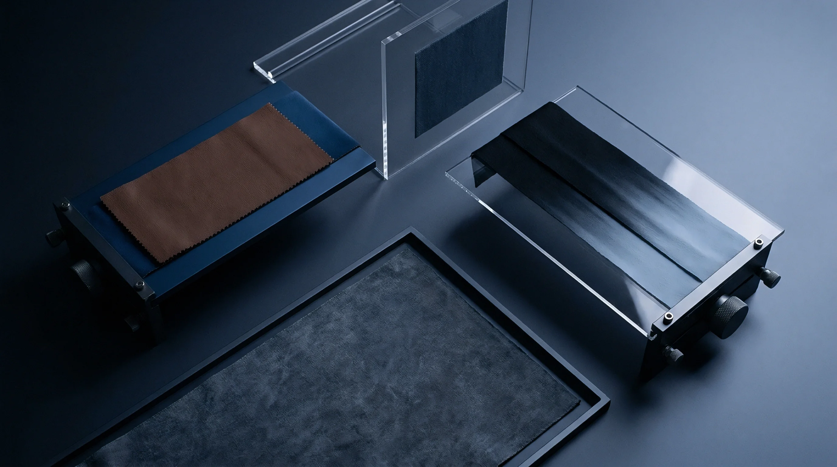
Direct mechanical coupling between instrument jaw faces and fabric specimens governs force transfer during seam opening tests. Inconsistent clamping dynamics introduce parasitic slippage inside the grips, distorting load-cell readings and invalidating mathematical curve comparisons. ASTM D4034 permits manual screw-action clamps, smooth steel faces, or pneumatic jaw systems.
GB/T 13772 testing within Chinese accredited laboratories standardizes almost exclusively on pneumatic clamps operating at controlled line pressures between 4 bar and 6 bar. When specimen ends move within jaw faces during tensile extension, instrument sensors record that displacement as seam opening, generating false failure reports on quality control ledgers.
Manual screw clamps rely entirely on technician technique to establish holding force. Technicians tightening clamp screws with manual T-handles generate holding forces ranging from 1.5 kN to 4.2 kN depending on operator fatigue and thread lubrication. Low clamping force allows smooth continuous filament yarns, such as 75-denier polyester or nylon linings, to pull out from jaw faces during load application.
High clamping force crushes delicate spun yarns, severing structural filaments at the jaw line and causing premature fabric tearing before seam slippage reaches target force thresholds. Pneumatic systems eliminate human variation by applying constant, verifiable pressure across calibrated piston areas.

Pneumatic Load Vs Manual Screw Torque
Quantifying jaw holding force requires calibrating pneumatic line pressure against effective surface clamping area. A 6 bar line pressure applied to a 50 mm diameter pneumatic cylinder generates approximately 1.18 kN of linear clamping force. If jaw faces measure 25 mm by 100 mm, effective clamping pressure reaches 0.47 N/mm².
Manual screw clamps tightened to 3 N·m torque produce variable surface pressures exceeding 1.2 N/mm² near the screw axis while fading toward outer jaw edges. Non-uniform clamping pressure across the specimen width allows outer warp yarns to stretch while center yarns remain anchored, creating non-linear stress profiles across the seam line.
Specimen distortion originating at the jaw interface propagates directly into the curve subtraction routine. As outer yarns slip from manual grips under ASTM testing, the unsewn baseline curve displays artificial elongation. When subtracted from the sewn curve, this artificial elongation compresses the calculated net seam displacement figure, making a weak seam appear compliant.
Conversely, under GB pneumatic clamping, uniform high-pressure retention prevents jaw slippage entirely. All crosshead motion transfers directly into specimen strain and seam yarn movement. The resulting GB test reports accurately reflect true structural seam displacement, exposing weak yarn-locking structures that manual origin testing obscured.
Jaw Face Friction and Vulcanized Rubber Hardness
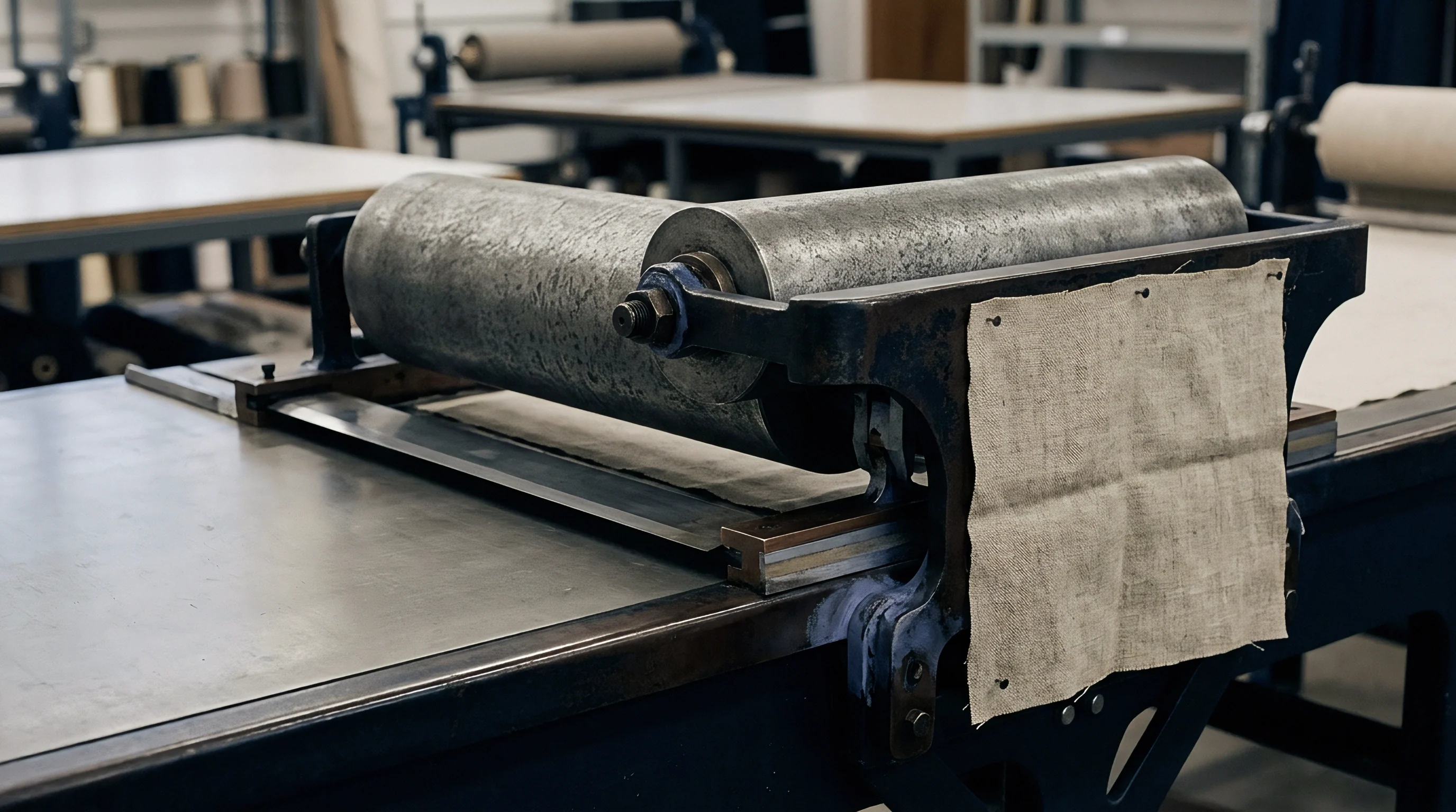
Face material selection alters boundary layer mechanics between metal jaw inserts and textile surfaces. ASTM D4034 allows smooth steel jaw faces, serrated steel inserts, or rubber-coated plates. GB/T 13772 protocols prefer smooth steel or high-durometer vulcanized rubber faces to prevent yarn cutting.
Steel jaw faces rely purely on dry friction against fabric surfaces. Rubber jaw faces deform under clamping pressure, gripping individual yarn crowns through mechanical interlocking. Rubber hardness, measured on the Shore A scale, dictates how far yarn crowns sink into the jaw coating under pressure.
Using low-durometer rubber jaw faces introduces compliance error into extension measurements. Soft rubber (50 Shore A) compresses laterally under vertical tensile loading. As the crosshead pulls upward, the rubber coating flexes upward by 0.5 mm to 1.5 mm before shear resistance halts movement.
Instrument load cells record this rubber deformation as crosshead travel, adding false extension units to both sewn and unsewn curves. High-durometer rubber (80 to 90 Shore A) resists shear deformation while maintaining mechanical interlock against yarn crowns. Laboratories failing to verify rubber jaw hardness introduce uncompensated calibration errors into batch verification reports.
Jaw slippage during tensile extension consistently masquerades as fabric seam movement when gripping smooth filament yarns.
Managing jaw mechanics demands systematic identification of grip interface failures during execution. The following list identifies critical failure modes encountered at the clamping boundary during dual-standard seam testing:
- Boundary Layer Slippage occurs when fabric surfaces slide between smooth steel jaw faces due to insufficient coefficient of friction, yielding artificial elongation values on force displacement charts.
- Transverse Compression Shear arises when soft vulcanized rubber jaw inserts deform vertically under tensile pull, introducing machine-compliance errors that corrupt curve subtraction algorithms.
- Yarn Crown Severing occurs when over-tightened serrated metallic jaws crush structural filaments at the clamp edge, causing fabric breakage at low force values before seam slippage completes.
- Asymmetric Pressure Gradient develops in manual screw grips when non-uniform torque application causes specimen edges to hold firmly while center zones pull free under load.
Calibrating clamping force requires inserting load cells directly between jaw faces to map pressure distribution across the gripping surface. Electronic tactile sensor arrays reveal pressure voids caused by worn jaw pivots or misaligned pneumatic pistons. Aligning jaw faces parallel within 0.02 mm prevents localized stress concentration.
If jaw faces clamp out of parallel, force concentrates on one edge of the specimen, initiating progressive seam failure from left to right across the stitch line. This progressive tearing mimics low seam slippage resistance under test conditions.
Machine compliance calibration isolates internal frame deflection from specimen extension. High-capacity load frames experience microscopic frame stretch, load cell deflection, and grip assembly movement under 100 N loads. Standard calibration procedures require clamping a solid steel plate between jaw faces and applying target test loads.
The resulting load-deflection curve records pure instrument deformation. Instrument software subtracts machine compliance data from raw fabric test curves. Omitting machine compliance calibration introduces up to 0.8 mm of systemic error into reported seam slippage values, directly causing destination audit failures under strict GB standards.
A twelve-thousand-dollar retest charge was incurred on a sixty-thousand-meter lot of technical outerwear fabric after failing to detect rubber jaw flex during initial testing.


Stitch
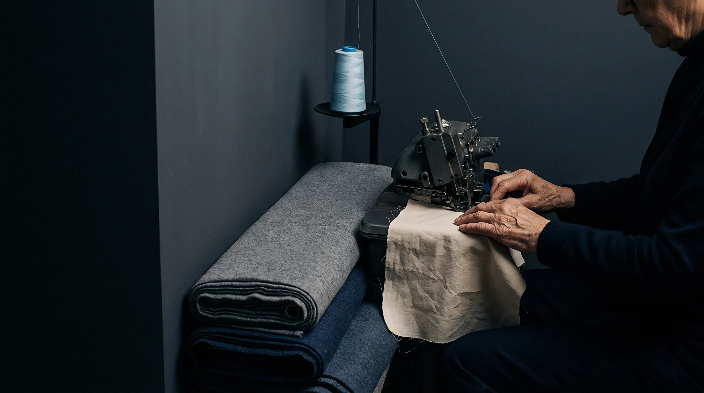
Sample preparation procedures dictate the mechanical geometry of the seam subjected to tensile force. Minor variations in needle diameter, stitch density, sewing thread elasticity, and seam allowance width alter internal force distribution among intersecting yarns. ASTM D4034 and GB/T 13772 specify distinct sewing parameters that prevent direct equivalence between test results unless specimens undergo precise normalization.
Preparing swatches under ASTM parameters produces structural seam behaviors that fail to match performance measured under GB standard conditions.
Needle selection alters yarn structural integrity along the seam line. ASTM D4034 calls for metric needle size 90 (Singer size 14) or size 110 (Singer size 18) depending on fabric mass, using light ball point or sharp needle geometries. GB/T 13772.1 specifies metric size 90 (Nm 90) for light-to-medium fabrics and metric size 100 (Nm 100) for heavy fabrics, enforcing precise needle eye dimensions and blade tapers.
Inserting a large needle through high-density woven fabrics severs warp or fill filaments, creating localized structural voids. Severed yarns lose structural anchorage within the weave, sliding under significantly lower tensile force than intact yarns.

Needle Displacement and Fabric Yarn Damage
Penetrating dense woven fabrics with an uncalibrated needle generates friction heat and structural yarn displacement. When an Nm 100 needle pierces a high-sett fabric, it forces adjacent yarns sideways, compressing neighboring weave spaces. This localized compaction increases inter-yarn friction around the needle hole while weakening the surrounding weave matrix.
Under tensile strain, displaced yarns slip easily through the widened needle perforation. ASTM protocols permit broader needle size selections, allowing origin facilities to select smaller needles that preserve fabric integrity. GB auditors re-testing the batch with mandatory Nm 100 needles induce higher yarn displacement, resulting in larger seam opening values.
Stitch density specifications create further structural disparity between origin and destination test reports. ASTM D4034 standardizes on 12 stitches per inch (approximately 4.7 stitches per cm). GB/T 13772.1 mandates 5.0 stitches per cm ± 0.2 stitches per cm (12.7 stitches per inch).
A higher stitch density places more sewing thread loops within a given length of seam, distributing applied tensile force across a greater number of contact points. Increasing stitch density from 4.7 to 5.0 stitches per cm increases force distribution points by 6.4 percent, theoretically enhancing seam resistance.
Stitch density increases also compress fabric yarns tighter within lockstitch loops. Tight lockstitch loops restrict yarn mobility, preventing fill yarns from sliding past warp yarns under tension. However, if stitch density exceeds fabric structural limits, repeated needle penetrations weaken the cloth along the seam axis, initiating stitch-line perforation failure.
Balancing stitch density against needle diameter determines whether seam failure manifests as pure yarn slippage or fabric rupture during crosshead extension.

Seam Allowance Friction and Sewing Thread Modulus
Seam allowance width governs edge friction resistance behind the stitch line. ASTM D4034 specifies a 13 mm (0.5 inch) seam allowance. GB/T 13772.1 mandates a 10 mm seam allowance for standard testing, with 15 mm permitted for specific technical fabrics.
The fabric strip extending beyond the seam line provides structural backing. As tensile force pulls structural yarns out of the seam, trailing yarn ends must slide through the seam allowance margin before full opening registers. A wider 13 mm seam allowance offers 30 percent more frictional length than a 10 mm allowance, increasing force required to pull yarn tails out of the matrix.
Testing fabrics with narrow 10 mm seam allowances under GB protocols reduces total edge friction. Tail ends of fill yarns clear the seam allowance border quickly, allowing rapid seam widening at lower load thresholds. Origin tests conducted under ASTM’s 13 mm allowance benefit from extended tail friction, recording high force values for 6 mm openings.
Buyers relying on origin ASTM compliance certificates discover that destination GB testing with 10 mm allowances yields premature seam opening failures under identical purchase order force specifications.
| Parameter Type | ASTM D4034 Specification | GB/T 13772.1 Specification | Operational Impact on Retest Data |
|---|---|---|---|
| Needle Size | Nm 90 (Size 14) or Nm 110 (Size 18) | Nm 90 or Nm 100 strictly assigned | Larger needles increase yarn damage in high-density weaves. |
| Stitch Frequency | 12 stitches per inch (4.7 stitches/cm) | 5.0 ± 0.2 stitches per cm | Higher frequency redistributes load but increases perforation risk. |
| Seam Allowance | 13 mm (0.5 inch) | 10 mm (standard) or 15 mm | Shorter seam allowance reduces friction on slipping yarn tails. |
| Sewing Thread Type | 100% spun polyester (Ticket 50/70) | 100% polyester core-spun (36 to 45 tex) | Higher thread modulus minimizes loop extension under load. |
| Stitch Type | ISO 4915 Stitch Type 301 (Lockstitch) | ISO 4915 Stitch Type 301 (Lockstitch) | Uniform thread tension prevents asymmetric loop distortion. |
Sewing thread tensile modulus governs internal loop deformation under load. ASTM D4034 permits standard spun polyester threads, whereas GB/T 13772 protocols dictate high-modulus polyester core-spun threads within specific linear density ranges (36 to 45 tex). Low-modulus sewing threads stretch under initial tensile loading before transferring force to fabric yarns.
This thread stretch absorbs initial crosshead travel, dampening force peaks registered by load cell sensors. High-modulus core-spun threads transfer force instantly into fabric yarn junctions, initiating seam movement at lower overall crosshead extension values.
Executing sample preparation requires strict adherence to sequential alignment protocols. Technicians follow this physical sequence when constructing seam test swatches for dual-standard laboratory correlation:
- Cut fabric specimens parallel to warp and fill directions using a calibrated rotary cutter, ensuring specimen dimensions measure exactly 100 mm by 350 mm.
- Mark seam lines using a fine fabric marker precisely 10 mm from the edge for GB testing or 13 mm from the edge for ASTM testing.
- Mount an undamaged, calibrated Nm 90 needle into the lockstitch sewing machine and check needle point smoothness under optical magnification.
- Adjust sewing machine thread tension control until upper and lower thread lock junctions seat exactly in the geometric center of the fabric specimen thickness.
- Sew test seams at a controlled machine speed under 800 stitches per minute to avoid thermal needle friction that weakens synthetic filament yarns.
Clause 6.2 of GB/T 13772.1 penalizes non-standard stitch density by invalidating the force curve whenever needle insertion cuts warp filaments.
Thread tension balancing prevents asymmetric seam distortion during load application. If top thread tension exceeds bobbin thread tension, lock junctions sit near the upper fabric surface. Under tensile strain, top thread loops pull straight, drawing bottom loops upward through needle holes.
This loop realignment creates 0.5 mm to 1.2 mm of initial structural slack before fabric yarns engage friction resistance. Standardizing sewing machine thread tension using electronic tension meters ensures lock junctions remain anchored in the fabric center core, eliminating thread-slapping artifacts during data collection.
Conditioning prepared seam swatches prior to mechanical testing stabilizes yarn crimp configurations altered during sewing operations. Sewing machine feed dogs introduce compressive strain along the seam line, bunching fabric yarns against stitch loops. ASTM D1776 and GB/T 6529 mandate preconditioning specimens at standard atmosphere (20 ± 2°C, 65 ± 4% relative humidity) for a minimum of 24 hours.
Testing swatches immediately after sewing, without moisture equilibrium conditioning, produces unstable friction coefficients between synthetic filaments, skewing recorded slippage forces by up to 15 percent.
Five stitches per centimeter is frequently treated as equivalent to twelve stitches per inch within commercial tolerance, despite the two millimeter gap variance registered on test reports.

Optics
Pinpointing the exact physical moment when a seam opens to a specified distance represents a major source of measurement uncertainty. ASTM D4034 relies on mechanical feeler gauges or manual curve subtraction calculations to identify target opening thresholds such as 6 mm. GB laboratories rely on non-contact digital optical systems integrated directly with constant rate of extension testing frames.
These optical systems track seam widening in real time at 50 to 100 frames per second. Optical measuring techniques capture microscopic yarn movements invisible to manual feeler gauges, recording smaller initial displacement thresholds and generating systematically different compliance results.
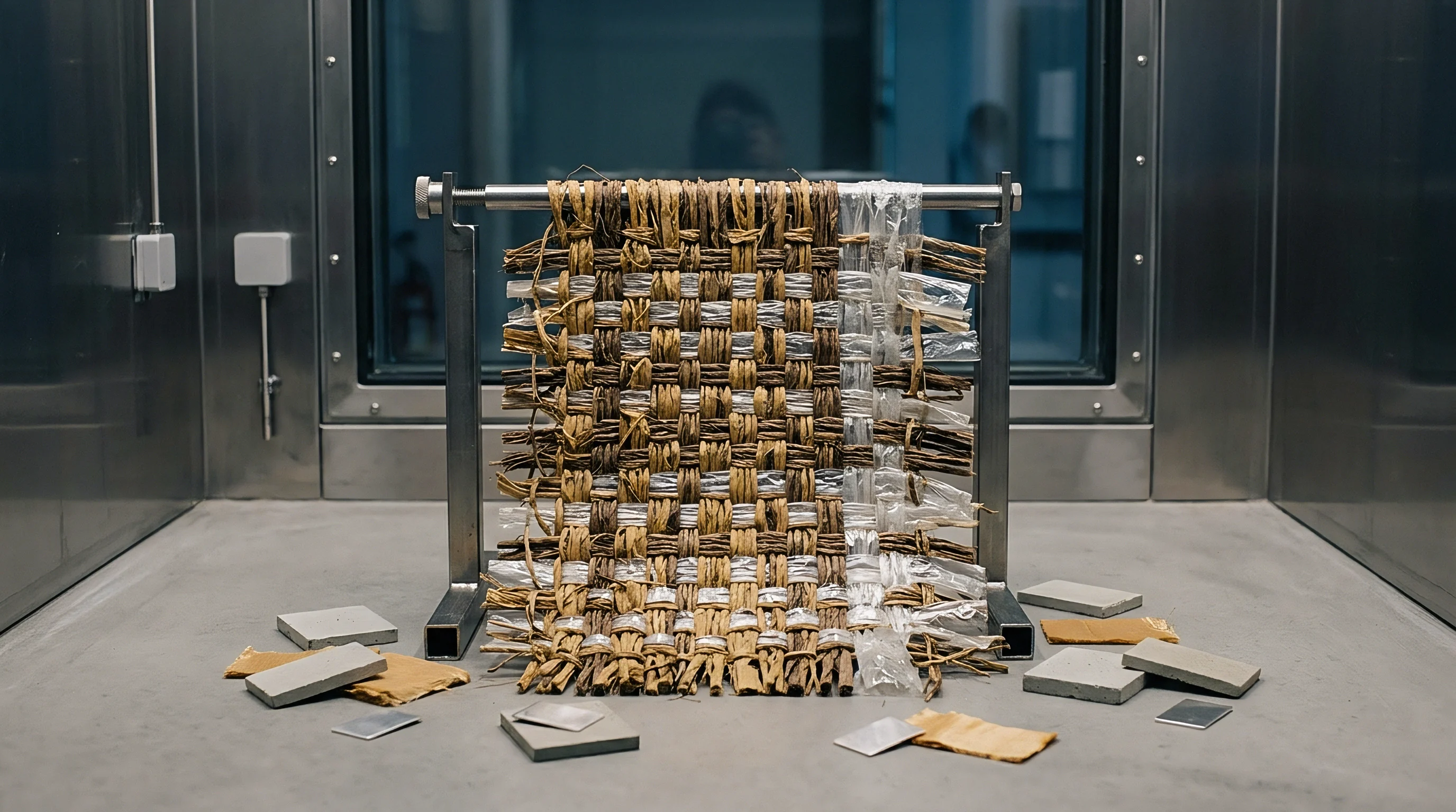
Manual feeler gauge inspection requires technicians to pause the testing machine or inspect the seam under static load. The technician inserts a tapered metal wedge or feeler gauge blade into the seam opening between parallel yarns. Inserting a physical steel blade forces yarns apart, adding mechanical displacement to the seam gap.
Human operator variation in feeler gauge insertion force introduces up to 0.6 mm of measurement error. Operators pushing feeler gauges firmly into seam gaps register target openings prematurely, reporting compliance at force values lower than true physical displacement requires.
Feeler Gauge Contact Resistance Vs Non Contact Pixel Mapping
Digital optical tracking systems eliminate physical contact errors by projecting high-intensity LED backlight through the specimen during extension. Monochromatic CMOS cameras capture high-resolution images of the seam line, analyzing light transmittance through widening spaces between structural yarns. Computer vision algorithms calculate seam opening distance by counting pixels exceeding calibrated brightness thresholds.
As yarns slide apart, light transmission increases proportionally. Optical systems detect light leakage through microscopic 0.1 mm yarn gaps, registering seam opening long before a technician can physically insert a standard feeler gauge blade.
Optical measurement algorithms must distinguish true yarn slippage from surface fabric fuzz and protruding filament ends. Low-grade filament yarns or hairy staple yarns project loose fiber ends across open seam spaces. These protruding fibers block backlight transmission, masking physical gaps between sliding yarns.
Advanced optical software applies edge-filtering filters to strip fiber noise from pixel calculations. If optical systems lack proper spatial calibration, surface fiber interference leads to underestimating true physical seam opening, creating compliance discrepancies between digital laboratories and manual inspection benches.

Could Image Analysis Resolve Manual Gauge Variance?
Deploying automated computer vision systems resolves human operator bias while introducing software parameter dependencies. Automated systems rely on threshold parameters to define where yarn edges end and open space begins. Setting grey-scale luminance thresholds too high causes the vision system to classify light-colored yarns as open space, overestimating seam widening on light fabrics.
Conversely, dark-dyed indigo or black fabrics absorb backlight, requiring specialized surface lighting angles to prevent edge detection failure. Calibration parameters must adapt dynamically to fabric color, weave density, and yarn reflectance.
Software algorithms track displacement using pixel mapping factors derived from calibrated optical calibration grids. A standard calibration grid features precision-etched chromium dots spaced at 1.000 mm intervals mounted on an optical glass sub-plate. Technicians place the grid in the specimen plane, aligning camera lenses until spatial resolution achieves a minimum of 40 pixels per millimeter.
Skimping on optical calibration allows lens distortion near image edges to warp millimetric distance calculations by up to 8 percent, rendering high-speed camera data invalid during accredited compliance audits.
Selecting appropriate measurement infrastructure requires matching optical capabilities against product risk levels. The decision checklist below outlines key factors when specifying seam evaluation technology for batch qualification:
- Spatial Resolution Verification requires ensuring camera sensors achieve at least 40 pixels per millimeter across the full 100 mm field of view to resolve sub-millimeter yarn movements.
- Backlight Luminance Uniformity demands verifying LED illumination arrays maintain consistent intensity within ±2 percent across the specimen area to prevent edge-detection threshold shifting.
- Surface Fiber Noise Filtering necessitates confirming vision software incorporates morphological opening filters that erase loose fiber ends from gap-width calculations.
- Dynamic Frame Rate Synchronization requires matching camera capture speed to crosshead displacement rates to acquire at least ten images per millimeter of crosshead travel.
Optical systems capture dynamic creep behavior during load-hold phases that static feeler gauges miss completely. Standard GB/T 13772.2 fixed-load protocols require applying a target force, such as 100 N, and holding that force for 10 seconds before measuring seam gap width. Under sustained load, synthetic yarns undergo viscoelastic stress relaxation, creeping slowly past stitch loops.
High-speed digital cameras record this time-dependent movement continuously, registering total creep opening at the final 10-second mark. Feeler gauge measurements taken manually during static holds allow load decay, under-reporting final creep displacement figures.
Non-contact measurement methods always yield smaller seam opening values than physical probes that force yarns apart during insertion.

Settlement
Resolving structural discrepancies between origin ASTM test reports and destination GB border audit findings requires commercial and technical alignment strategies. When imported garments face detention at Chinese ports under mandatory GB 31701 or GB 18401 safety codes due to seam slippage failure, financial losses escalate rapidly through demurrage charges, re-testing fees, and customs penalties. Sourcing practices must translate physical standard differences into contractual safety margins, establishing bulletproof quality assurance procedures that bridge origin certification with destination market surveillance.
Commercial contracts often state seam slippage limits using simplified parameters, such as “Seam Slippage < 6 mm under 100 N load.” This naive framing fails to specify whether evaluation follows ASTM D4034 curve offset methods or GB/T 13772.1 CRE force subtraction algorithms. A fabric clearing 6 mm under ASTM D4034 at 100 N will frequently register 7.5 mm to 9.0 mm under GB/T 13772.1 due to pretension baseline offsets and continuous curve subtraction. Sourcing engineers write precise purchase orders that mandate testing under target destination protocols prior to export container loading.

Contractual Alignment and Laboratory Correlation Factors
Establishing empirical correlation factors between ASTM and GB test data allows mills to target safe origin quality limits. Sourcing teams perform dual-standard calibration trials on specific fabric qualities, generating regression curves that link ASTM D4034 performance to GB/T 13772.1 outcomes. For example, statistical analysis of 200 g/m² woven wool blends indicates that achieving a GB/T 13772.1 pass limit of 4.0 mm under 100 N requires origin ASTM D4034 performance to reach 2.5 mm or less under identical force.
Sourcing teams embed these tightened internal engineering limits into mill production specifications.
Contractual language must explicitly assign financial liability for destination test failures resulting from methodology divergence. Standard purchase order amendments include clauses defining destination accredited laboratory re-testing as the final authority for batch acceptance. Sourcing practices require mills to provide transaction testing certificates issued by ISO/IEC 17025 accredited facilities whose scope specifically includes GB/T 13772 standards.
Relying on scope certificates that cite general ASTM methods leaves buyers exposed to border rejection without legal recourse against converting mills.
| Fabric Construction Class | Origin ASTM D4034 Result | Destination GB/T 13772.1 Result | Border Detention Risk Level | Commercial Exposure Mitigation Action |
|---|---|---|---|---|
| Lightweight Filament Lining (70 g/m²) | 3.8 mm at 80 N | 6.2 mm at 80 N | High (Exceeds 6 mm limit) | Tighten origin internal target to < 2.5 mm; change stitch density. |
| Medium Wool-Poly Suiting (220 g/m²) | 4.0 mm at 100 N | 5.4 mm at 100 N | Moderate (Near 6 mm threshold) | Enforce Nm 90 needle control; apply 5 N pretension correction factor. |
| Heavy Cotton Twill Outerwear (320 g/m²) | 2.1 mm at 120 N | 3.1 mm at 120 N | Low (Compliant) | Maintain current weave settlement and 10 mm seam allowance parameters. |
| Stretch Spandex Blend (180 g/m²) | 5.2 mm at 100 N | 7.8 mm at 100 N | Critical (Immediate Rejection) | Redesign seam construction; incorporate high-modulus stay-tape support. |
Managing financial exposure demands calculating total landed re-test costs against potential customs liabilities. Holding a delayed container at destination ports incurs demurrage charges averaging 150 to 300 USD per day per container, alongside accredited re-testing fees of 250 USD per swatch sample. If destination market surveillance flags a non-compliant garment batch under GB 31701 children’s wear rules, total exposure includes inventory confiscation, fines up to three times invoice value, and mandatory public recall notices.
Implementing rigorous destination-aligned testing at origin eliminates border detention risk entirely.
Verification protocols must trace batch compliance down to specific roll numbers and dye lots. Mills frequently submit hand-samples or specially sewn swatches for initial qualification, then ship production rolls with lower stitch density or uncalibrated sewing thread tension. Sourcing practices implement random lot acceptance sampling, drawing production swatches directly from packed containers prior to port delivery.
Testing container swatches against GB/T 13772.1 under strict ISO/IEC 17025 laboratory conditions ensures shipped cloth mirrors certified performance.
A batch clearing origin testing under American protocols frequently fails destination market surveillance when seam opening equations omit pretension offset values.
Addressing structural discrepancies between ASTM and GB seam slippage testing requires systematically standardizing kinematic baseline assumptions, clamping pressure distribution, needle penetration geometry, and optical evaluation methods. When buyers, converters, and accredited testing laboratories align physical sample preparation and mathematical curve processing across global supply chains, seam slippage measurements stabilize into predictable, repeatable performance metrics. Technical compliance shifts from an unpredictable border hurdle into a verifiable quality fact embedded directly within the commercial transaction file.
Section 14 of the standard export agreement assigns full chargeback liability to the weaving mill whenever destination GB testing yields seam slippage exceeding four millimeters under a hundred Newton load.