Calibrating Force Curve Subtraction for Yarn Slippage Measurement in ASTM D4034
Subtracting unsewn load curves from sewn seam curves in ASTM D4034 isolates true yarn slippage by removing raw fabric extension errors.
Baseline
Measurement of yarn slippage under ASTM D4034 isolates seam opening from fabric tension. In woven upholstery construction, applying a tensile force across a sewn seam stretches both the constituent yarns and the seam assembly. Standard testing protocols evaluate resistance to yarn slippage at the sewn seam by comparing two distinct force-extension curves generated on a constant-rate-of-extension tensile testing machine.
One curve records the response of the unsewn fabric under load. The second curve records the response of a specimen containing a standardized seam sewn parallel to either the warp or filling yarns.
The core analytical procedure requires subtracting the extension of the unsewn fabric from the extension of the sewn fabric at a specified load. This mathematical subtraction eliminates raw fabric stretch from the total displacement recorded across the seam area. The remaining distance represents pure yarn slippage, defined as the physical displacement of warp yarns over filling yarns, or vice versa, along the seam line.
Raw force curves tell part. Accurate determination of resistance to yarn slippage depends entirely on establishing a precise baseline alignment between these two load curves.
When the unsewn and sewn specimens do not share identical initial tension conditions, the calculated displacement values become corrupt. A small offset in the initial zero point shifts the entire subtracted curve along the extension axis. In laboratory practice, this shift causes substantial errors in the calculated seam opening distance, typically measured at 6.35 mm (1/4 inch) or 3.18 mm (1/8 inch) thresholds.
The load cell records force.
Force Curve Principles
Tensile testing instruments generate continuous load-displacement records during specimen elongation. In ASTM D4034 testing, a upper jaw speed of 305 mm per minute pulls the fabric specimen until a load of 222 N or seam failure occurs. The chart or digital recorder captures force on the vertical axis and distance on the horizontal axis.
For unsewn fabric, the curve reflects structural crimp removal followed by yarn elongation. For sewn specimens, the curve incorporates these same fabric deformation modes alongside needle thread deformation, seam tightener alignment, and yarn displacement at the stitch points.
A load offset exceeding 1.2 N between unsewn and sewn load curves at initial tension invalidates yarn slippage distance calculation across a 200 mm gage length.
Subtracting unsewn fabric extension from total seam extension isolates structural seam performance. Without subtraction, a fabric with high yarn elasticity shows false resistance to slippage because total extension appears large prior to seam opening. Conversely, a rigid fabric shows abrupt force increments that mask early yarn movement.
Isolating the net seam displacement profile reveals the exact load where structural weave failure initiates.
Mathematical Subtraction Mechanics
The procedure pairs two force records generated at identical crosshead speeds. At any given force value, represented as Fi, the recorder notes the total displacement of the unsewn fabric (Du,i) and the total displacement of the sewn fabric (Ds,i). The net seam opening displacement (Dnet,i) calculates directly through scalar subtraction:
Dnet,i = Ds,i – Du,i
When executing this calculation across the full loading profile, the laboratory constructs a derived force-versus-net-displacement curve. ASTM D4034 defines resistance to yarn slippage as the force required to produce a specified net seam opening, or alternatively, the net seam opening distance produced at a specified force limit. Precise calibration of the origin point for both primary curves governs the absolute accuracy of Dnet,i.
| Parameter | Standard Tolerance | Calibration Limit | Impact on Subtraction |
|---|---|---|---|
| Force Accuracy | +/- 1.0 % of reading | 0.05 N resolution | Errors alter vertical load matching points |
| Extension Measurement | +/- 0.1 mm | 0.01 mm resolution | Direct displacement error in net subtraction |
| Crosshead Speed Control | 305 +/- 10 mm/min | 305 +/- 2 mm/min | Speed variations alter fabric strain rate response |
| Preload Zeroing Limit | 0.5 N to 1.0 N | 0.1 N threshold | Misaligned zero load shifts horizontal baseline offset |
Incorrect subtraction offsets distort measured seam opening distances, leading to rejected upholstery shipments or unearned product failure claims.

Clamp
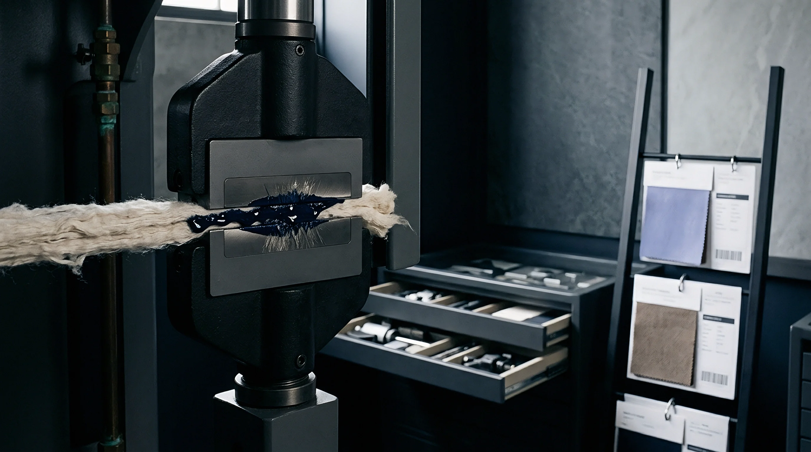
Mechanical gripping systems introduce physical compliance into force-displacement data. In ASTM D4034 testing, specimens secure within pneumatic or manual mechanical jaws attached to the load frame. Jaw face selection, clamp pressure, and rubber insert durometer directly alter the recorded extension profiles.
If the specimen slips within the jaw face during loading, the recorded crosshead displacement reflects both true fabric extension and mechanical jaw slip. Clamp deformation skews the array.
Jaw slippage alters unsewn and sewn specimens at different force thresholds due to variations in total specimen stiffness across the clamped width. Standard ASTM D4034 methods specify extra wide back jaw faces measuring 50.8 mm by 38.1 mm paired with front jaw faces measuring 25.4 mm by 25.4 mm, creating a focused stress field. This asymmetrical clamp geometry forces stress concentration around the central 25.4 mm strip of fabric containing the seam.
When clamping forces drop below critical thresholds, local fabric compression causes micro-displacement inside the jaw faces before structural yarn slippage occurs at the seam line. This artificial extension corrupts the force curve subtraction. Precision demands exact gage alignment.
Pneumatic Pressure Controls
Air pressure applied to testing jaws dictates surface friction at fabric contact points. Pneumatic clamping systems maintain constant pressure throughout specimen elongation, compensating for thickness reduction as fabrics stretch under load. Manual screw clamps lack this dynamic compensation, suffering from pressure decay as yarns flatten.
For heavy woven upholstery fabrics, pneumatic operating pressures between 0.55 MPa and 0.70 MPa prevent internal specimen movement without crushing constituent yarns.
Pneumatic clamp pressure calibrated below 0.45 MPa permits specimen slippage inside jaw faces, artificially widening reported seam opening values beyond true weave displacement.
Insufficient clamp pressure manifests as extended non-linear toe regions at the start of force-extension curves. When subtracting an unsewn curve with minimal jaw slip from a sewn curve with significant jaw slip, the mathematical net result indicates severe seam opening at low loads where none exists physically. Mechanical clamp integrity functions as a primary boundary condition for valid test data.
Mounting Slippage Vectors
Specimen movement within securing faces creates artificial extension on test curves. To detect and control mounting compliance during ASTM D4034 evaluations, laboratories evaluate mechanical mounting failure modes against explicit technical indicators.
- Jaw Face Friction Loss occurs when smooth steel surfaces fail to grip high-luster filament yarns, causing linear displacement offsets during loading.
- Pneumatic Pressure Decay results from leaking supply lines or failing cylinder seals, reducing holding force during high-load crosshead travel.
- Gage Length Asymmetry happens when non-parallel jaw mounting twists the fabric, causing uneven stress distribution across the central seam region.
- Gasket Cushion Compression develops when worn rubber jaw face inserts yield non-linearly under increasing force, adding false machine compliance to fabric extension values.
- Specimen Flashing Alignment Failure emerges when central seam orientation shifts away from perpendicular relative to the crosshead pulling vector.
Jaw pressure alters the curve. Mill quality managers routinely attribute anomalous initial curve slopes to jaw cushion compression rather than specimen slippage inside the gripping faces.
Deformation
Woven upholstery fabrics undergo structural rearrangement prior to yarn movement along sewn seams. Applying tensile load to a woven structure engages complex interactions between warp and filling thread systems. Crimp interchange dominates early deformation, where curved yarns straighten while pushing opposing straight yarns into higher crimp states.
Yarn crimp delays force buildup. This structural adjustment generates non-linear force-extension behavior during initial loading phases.
In sewn specimens, needle insertion alters local fabric architecture. The sewing needle displaces structural yarns, creating localized voids and altering local yarn density along the seam line. The seam gives way first.
As external load increases, needle thread tension holds the seam stitches while surrounding structural yarns deform. Disentangling intrinsic fabric extension from needle hole elongation demands precise curve alignment.
Viscoelastic strain adds time-dependent variables to this physical system. Synthetic upholstery yarns composed of polyester, polypropylene, or nylon exhibit rate-dependent extension under load. Elastomeric or textured yarns intensify this response, non-linearly altering the force curve profile.
When Does Fabric Extension Mask Seam Opening?
High-twist yarns and dense weave constructions absorb initial tensile loads through crimp interchange. During this phase, structural yarns shift position without sliding past neighboring yarns at the seam line. The force curve exhibits a low-modulus toe region.
If unsewn and sewn fabric specimens exhibit different crimp levels due to sewing thread tension, subtracting unsewn extension from sewn extension yields negative net values at low loads.
Negative displacement values signify mathematical artifact creation rather than physical fabric behavior. To eliminate these artifacts, testing operators execute standardized specimen mounting routines under controlled initial tension.
- Cut unsewn and sewn specimens to 100 mm width by 200 mm length parallel to warp or filling directions.
- Mark a reference line exactly 38 mm from the specimen end for seam placement.
- Sew test seams using standard gauge sewing thread with 4.7 stitches per centimeter under controlled thread tension.
- Calibrate tensile frame gage length to precisely 75 mm between upper and lower jaw faces.
- Apply a standardized preload of 1.0 N across the full specimen width prior to clamping lower jaws.
- Verify specimen vertical alignment using precision grid marking board.
- Execute crosshead elongation at 305 mm per minute until maximum load target is reached.
Subsetting load data past the initial crimp interchange zone isolates structural yarn movement from baseline weave extension.
Viscoelastic Yarn Recovery
Synthetic yarns display time-dependent strain behavior during mechanical loading cycles. When loaded at standard test speeds, viscoelastic relaxation alters force curve slopes. Fast loading rates increase apparent fabric modulus, whereas slow loading allows yarn creep.
Because ASTM D4034 employs continuous crosshead motion, strain rate sensitivity directly affects the subtraction output when unsewn and sewn specimens exhibit differing stress distribution profiles across clamped areas.
Weave structure governs slip force. Fabrics constructed with high crimp stability maintain linear subtraction behavior across increasing load levels.

Signal
Digital data acquisition systems convert analog force sensor voltages into discrete coordinate pairs. Tensile frames digitize load and displacement data at fixed sampling frequencies, typically ranging from 100 Hz to 1000 Hz. The load cell records discrete force-extension data points rather than continuous mathematical lines. Subtracting discrete digital arrays requires identical displacement or force sampling points across both unsewn and sewn datasets.
Data points require uniform spacing.
Interpolation errors emerge when digital signals lack identical data array lengths. If the unsewn specimen breaks or reaches peak load at a different extension than the sewn specimen, point-by-point subtraction requires signal resampling routines. Digital subtraction isolates the shift.
Modern testing software applies algorithmic smoothing to eliminate high-frequency electronic noise without dampening true structural yield signals.
Misaligned zero-force coordinates propagate through digital subtraction algorithms, creating cumulative displacement errors across the full load range.
Sampling Rates and Data Arrays
High-speed load sensors capture thousand-point arrays across five centimeters of crosshead travel. High sampling rates capture rapid force drops caused by individual yarn slip events across stitch lines. Low sampling rates blur these stick-slip events into smoothed averages, concealing initial seam yield thresholds.
| Processing Method | Data Resolution | Alignment Mechanism | Error Vulnerability | Repeatability (CV %) |
|---|---|---|---|---|
| Manual Graphic Overlay | Visual (0.5 mm grid) | Manual tangency line alignment | Operator subjective bias | 6.5 % |
| Linear Point Subtraction | Fixed load increments (1 N) | Static 1.0 N preload zeroing | Crimp region interpolation error | 3.2 % |
| Dynamic Array Interpolation | 1000 Hz digitized points | Modulus peak alignment | High-frequency sensor noise | 1.1 % |
| Polynomial Curve Fitting | 3rd-order curve fit equations | Derivative zero-crossing alignment | Over-smoothing structural yield points | 1.8 % |
Higher digitization rates improve displacement resolution, allowing detection of micro-slippage before visible seam openings develop.

Algorithmic Offset Alignment
Software routines shift unsewn displacement vectors to align with initial seam pretension values. Automated algorithms scan force arrays for initial contact force thresholds, establishing standardized origin coordinates (0,0) prior to mathematical array processing. Quality control checks ensure algorithmic alignment routines operate within strict parameters.
Digital curve subtraction aligned to initial contact tension rather than peak modulus yields consistent net displacement profiles across variable fabric densities.
- Force Threshold Zeroing sets origin points at the exact instant force exceeds 0.2 N, eliminating ambient air resistance and clamp weight artifacts.
- Linear Array Splining calculates intermediate displacement values using cubic spline interpolation when raw sampling rates vary between test runs.
- Modulus Matching Search identifies linear elastic zones on both curves to correct for structural mounting tilt before executing array subtraction.
- Noise Suppression Filtering applies digital low-pass filtering to remove mechanical motor vibration spikes without attenuating true yarn yield points.
Section 11.2 of ASTM D4034 specifies that net slippage values derive from curves aligned at initial preload, which alters reported seam strength results across lightweight woven structures.
Friction
Inter-yarn resistance within woven structures defines resistance to seam opening under load. When a sewing thread pulls perpendicular to structural yarns, sliding resistance relies on coefficient of friction between warp and filling filaments, yarn contact pressure, and weave geometry. High inter-yarn friction keeps yarns anchored, forcing seam stress onto needle threads.
Low inter-yarn friction permits easy yarn sliding, causing wide seam openings at minimal loads. The unsewn specimen provides zero.
Yarn finishes, lubricant additives, and chemical softeners alter boundary layer friction. Silicone softeners applied during fabric finishing drop inter-yarn friction coefficients significantly, drastically reducing seam slippage resistance. Conversely, fluorochemical or resin finishes lock yarns in place, artificially boosting slippage thresholds.
Identifying finished-induced slippage shifts requires thorough document verification against batch production records.
Commercial disputes arise when chemical finishes wash out or degrade during use, reducing inter-yarn friction and exposing underlying structural weak points.
Yarn Finish and Lubricant Impact
Chemical processing agents applied during finishing alter filament boundary sliding thresholds. Hydrophobic softeners reduce boundary friction between synthetic filaments, enabling easy displacement under low crosshead force. Downstream converters must audit chemical application rates to maintain compliance with commercial seam slippage specifications.
A mill test report omitting unsewn fabric reference curves prevents verification of calculated slippage against raw load data.
Auditing mill compliance dossiers requires verifying complete documentation sets. A compliant test file contains specific structural and procedural records.
- Raw Load Curves showing original force-extension output for both unsewn and sewn test specimens.
- Calculated Subtraction Profiles displaying net seam displacement array data.
- Fabric Construction Data listing verified warp/weft thread counts, yarn linear density, and finish designations.
- Sewing Conditions Specification documenting needle size, stitch type, thread identification, and stitches per inch settings.
- Testing Equipment Records confirming load cell calibration dates, pneumatic clamp operating pressures, and crosshead speed validation logs.
Warp and Weft Thread Counts
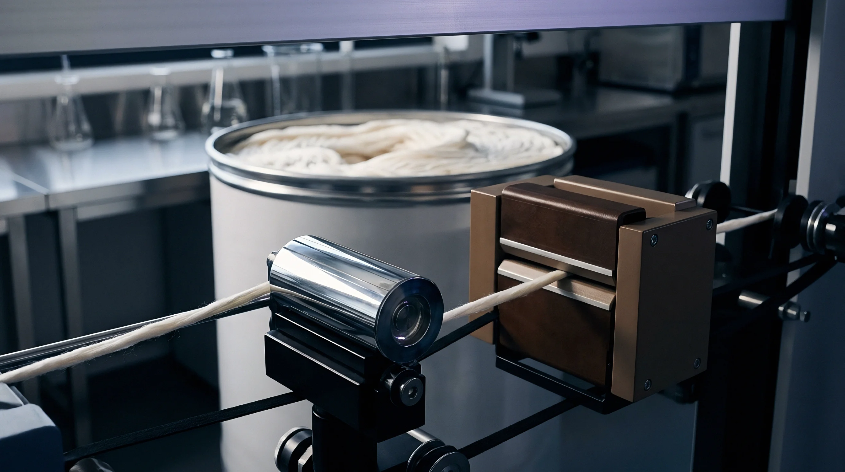
End and pick densities govern contact points per unit area across the seam line. High thread counts increase total contact area, multiplying cumulative inter-yarn frictional resistance. Low thread count upholstery fabrics, such as loose accent weaves, lack adequate contact density, relying heavily on yarn crimp or secondary backing compounds to prevent seam slippage.
Commercial risk follows poor math.
The exact contribution of silicone softener breakdown to long-term seam slippage under cyclic commercial seating stress remains an open area of investigation.
Tolerance
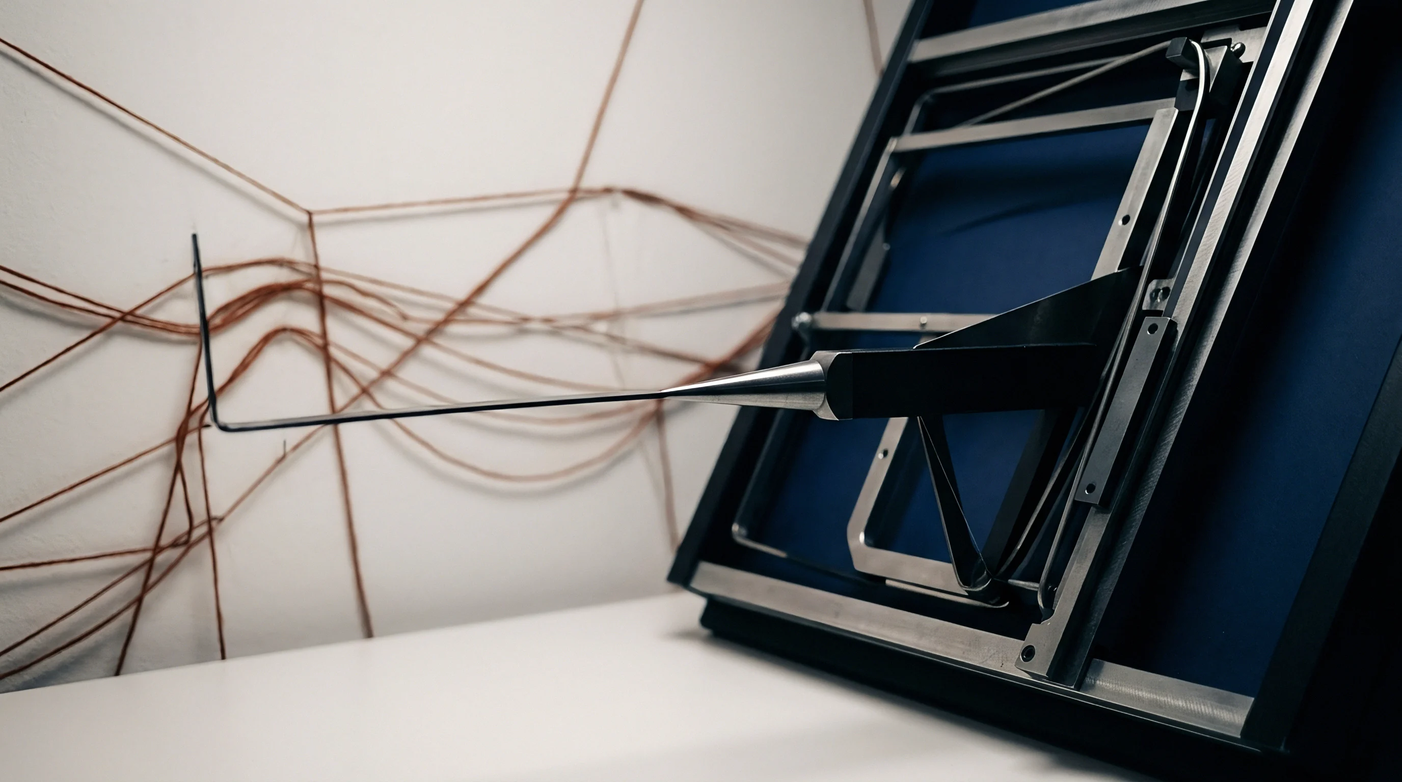
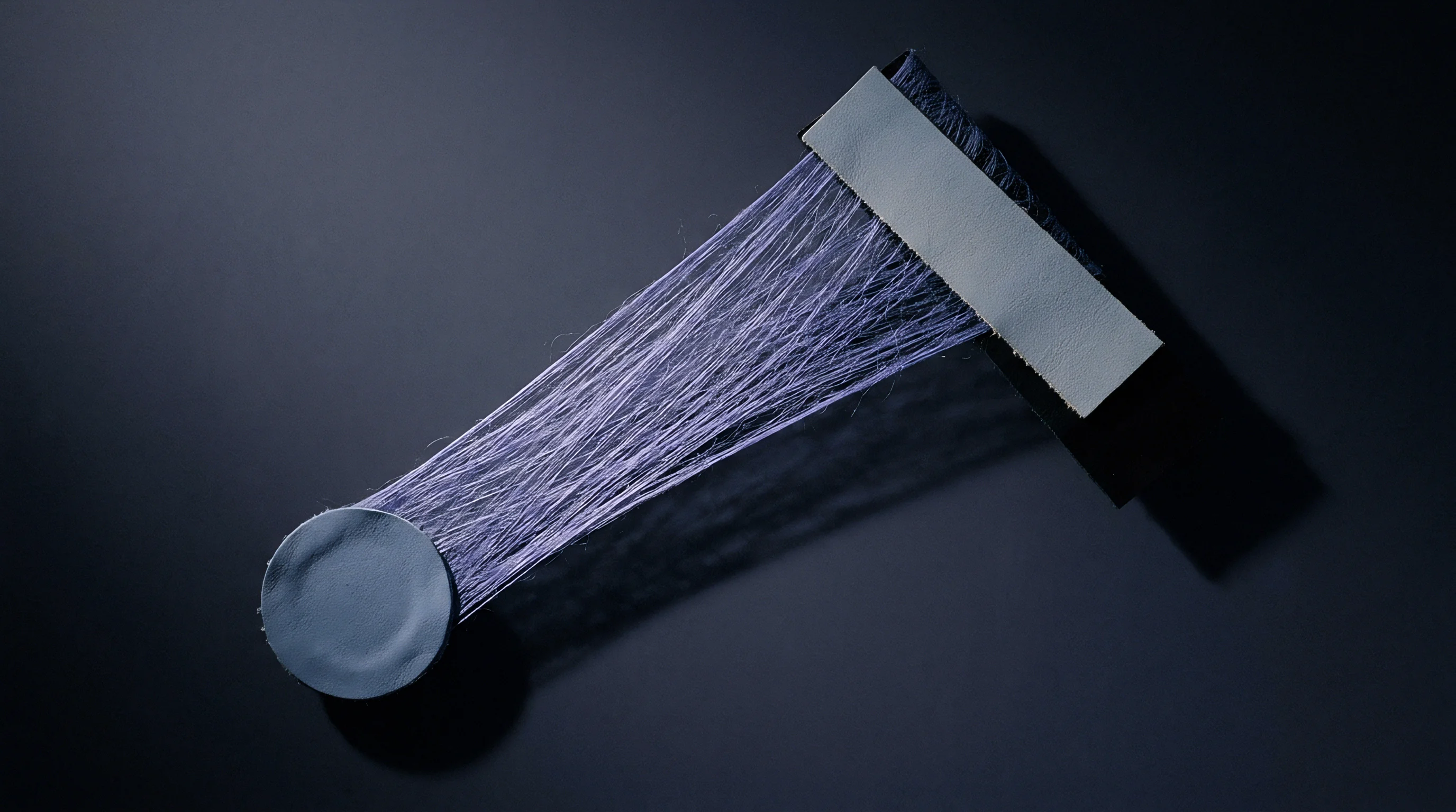
Commercial purchasing agreements define specific seam displacement limits measured in millimeters at fixed loads. Standard upholstery specifications, such as those established by the Association for Contract Textiles (ACT), require a minimum resistance to yarn slippage of 111 N (25 lbf) for light-duty upholstery and 222 N (50 lbf) for heavy-duty commercial applications, maintaining seam openings below 6.35 mm (1/4 inch). Seam opening defines the limit.
When force curve subtraction calibration is executed improperly, reported values deviate from true physical performance. An over-corrected baseline offset reduces reported net extension, creating a false passing result for a fabric that slips excessively in real seating applications. Conversely, under-corrected baseline alignment exaggerates seam opening, causing inappropriate batch rejections and commercial disputes between mills and furniture manufacturers.
The border inspector holds cargo.
Managing liability requires integrating clear technical parameters into purchase orders, specifying curve subtraction protocols alongside standard testing numbers.
Commercial Pass Criteria
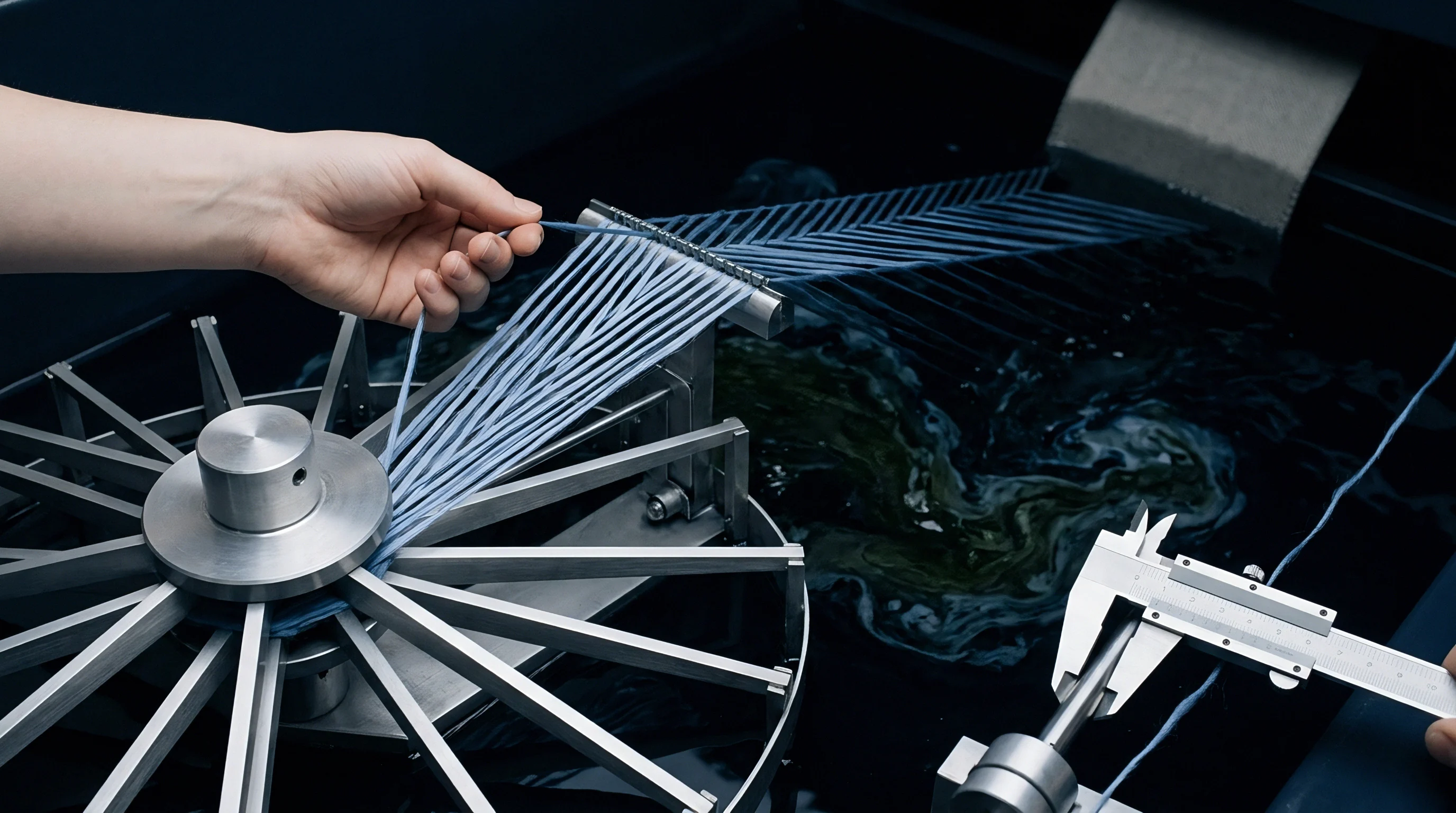
Brand quality specifications set maximum allowable seam openings between three and six millimeters. Testing facilities evaluate incoming fabric rolls using standardized statistical sampling, testing warp and filling directions across multiple roll locations. The table below outlines commercial pass thresholds, failure modes, and liability allocations for seam performance failures.
| Application Class | Minimum Force Threshold | Max Seam Opening | Primary Failure Mechanism | Commercial Liability Party |
|---|---|---|---|---|
| Heavy-Duty Contract Upholstery | 222 N (50 lbf) | 6.35 mm (0.25 in) | Inter-yarn sliding at stitch line | Weaving Mill / Converter |
| Light-Duty Residential Seating | 111 N (25 lbf) | 6.35 mm (0.25 in) | Yarn crimp collapse under load | Weaving Mill |
| Decorative Accent Trim Fabrics | 67 N (15 lbf) | 3.18 mm (0.125 in) | Low pick density weave opening | Product Developer / Buyer |
| Coated Upholstery Substrates | 178 N (40 lbf) | 6.35 mm (0.25 in) | Coating film tearing at needle holes | Coater / Finisher |
| Note: Compliance determinations require verified dual force curve subtraction files with pneumatic jaw pressure logged at 0.55 MPa. | ||||
Failure to meet specified force thresholds triggers batch rejections, chargebacks, or mandatory secondary testing at accredited independent laboratories.
Liability and Retest Clauses
Disputed test results trigger secondary verification protocols at third-party certified testing laboratories. Purchase order clauses must specify exact retest conditions, including clamp pressure settings, sampling rates, and curve offset zeroing methods. Clear specification of curve subtraction parameters inside purchase orders protects importers from arbitrary batch rejections at destination ports.