Dynamic Pressure Transducer Calibration in Multi Chamber High Temperature Jet Vessels
Dynamic pressure transducer calibration in jet vessels demands thermal sweep profiling to prevent inter-chamber flow imbalance and fabric unlevelness.

Drift
Piezoelectric sensors mounted on the liquor circulation lines of multi-chamber high-temperature jet vessels experience signal degradation when process temperatures cross 130 degrees Celsius. Pressure pulses generated by liquor flow through the venturi nozzles register inaccurate amplitudes once the sensing diaphragm absorbs repeated thermal cycling. The primary consequence appears as unmonitored liquor velocity shifts across adjacent dyeing tubes.
If liquor circulation drops inside one vessel chamber while maintaining programmed nozzle pressure readings, the fabric rope slows down. That deceleration alters the liquor-to-goods contact time, creating rope marks and unlevel disperse dyeing on tight polyester microfiber wovens.
Signal decay accelerates under dynamic thermal regimes. Piezoelectric quartz elements lose polarization linearity as internal housing temperatures climb toward maximum ratings, causing baseline shift during rapid heating cycles between 80 degrees Celsius and 135 degrees Celsius. Strain-gauge transducers experience zero-shift and sensitivity span errors caused by thermal expansion mismatches between the stainless steel diaphragm and the resistive foil grid.
In a four-chamber jet vessel processing textured polyester interlock knit at 130 degrees Celsius under 0.35 megapascals of system pressure, an uncalibrated transducer can under-report dynamic chamber nozzle pressure by 0.04 megapascals. The circulation pump responds by driving additional flow, forcing liquor through the jet ring above the fabric’s sheer limit.
Thermal gradients across sensor housings alter diaphragm stiffness coefficients, shifting raw millivolt output independent of line pressure.
Maintaining measurement integrity requires separating static hydrostatic head pressure from dynamic jetting pulses. Static vessel pressure keeps liquor liquid above boiling point, typically maintained with compressed air cushions or pressurized expansion tanks. Dynamic pressure dictates the hydraulic force drawing the continuous rope through the transport tube.
When processing delicate filament warps, excessive dynamic pressure tears micro-denier filaments, producing surface fuzzing that permanently ruins fabric face appearance. Insufficient dynamic pressure allows the textile rope to stall inside the chamber bottom, producing localized temperature spikes and permanent crease marks.
Calibration protocols must decouple these combined pressures through controlled temperature sweeps. The factory floor frequently treats transducer error as mechanical nozzle fouling, stripping assemblies unnecessarily while leaving electronic drift unaddressed. When sensor offset shifts by more than five percent across a four-hour dye cycle, closed-loop pump inverters fail to regulate rope velocity within required production bands.
Port
Transducer installation geometry dictates mechanical signal transmission fidelity. Multi-chamber jet dyeing vessels generate severe acoustic noise from centrifugal pump impellers, steam injection spargers, and turbulent flow across venturi constrictions. Direct flush mounting places the sensing face in contact with high-velocity liquor containing aggressive chemical auxiliaries, carriers, and acidic leveling agents.
A recess mounting creates a dead-leg cavity where oligomers, lint, and unfixed dye agglomerates collect over successive production cycles.
Acoustic Resonance and Impulse Line Sizing
Connecting sensors via standoff pipes isolates electronic assemblies from destructive bath temperatures. Standpipe length acts as an acoustic low-pass filter while establishing a thermal dissipation zone. A straight impulse tube filled with stagnant water creates a steep temperature gradient, protecting the transducer crystal while cooling process liquor below 60 degrees Celsius before it meets the diaphragm.
Incorrect pipe diameter introduces Helmholtz resonance that distorts high-frequency pressure peak readings. A narrow capillary chokes pressure pulses, rounding off sharp transients caused by rope knots clearing the nozzle opening. A wide tube allows internal thermal convection currents that destabilize baseline sensor readings.
| Mounting Configuration | Impulse Tube Bore (mm) | Temperature at Diaphragm (°C) | Frequency Cutoff (Hz) | Oligomer Fouling Risk |
|---|---|---|---|---|
| Direct Flush Diaphragm | 0.0 | 135 | 2500 | Extreme |
| Short Standoff Tube | 6.0 | 85 | 450 | Moderate |
| Siphoned Impulse Line | 10.0 | 45 | 120 | Low |
| Diaphragm Seal with Capillary | 2.0 | 55 | 35 | Negligible |
Fluid viscosity inside impulse tubes shifts across the dyeing cycle. As temperatures drop along the cooling standoff, bath fluid thickens, attenuating the amplitude of fast pressure spikes. Calibration routines must establish transfer functions that account for this hydraulic dampening.
Testing impulse lines using room-temperature water yields high-frequency responses that vanish when viscous dye liquors fill the chamber during production.
Transducer orientation on the jet manifold alters long-term calibration stability. Upward-angled ports collect entrained air bubbles, producing compliance cushions that suppress dynamic pressure pulses. Downward-angled ports collect precipitated polyester trimers and fiber fragments shed by spun yarns during high-temperature scouring.
Horizontal port installations with a slight downward slope toward the main pipe run minimize air pocket accumulation while allowing particulate matter to flush back into the main circulation stream.
A supplier who claims pressure transmitter isolation eliminates temperature errors overlooks oil-filled capillary volume expansion, which alters the factory zero offset as ambient manifold temperatures rise.

Sweep
Multi-chamber jet machines operate identical fabric ropes in parallel compartments fed by a common circulation pump and split manifold. Chamber-to-chamber balance ensures lot shade uniformity. When dynamic pressure transducers fall out of relative alignment, flow diverted across individual nozzles varies silently.
A four-chamber machine operating with an undetected fifteen kilopascal variance across compartments delivers split dye lots where chambers one and two yield deeper shades than chambers three and four due to altered liquor circulation frequency.
Can Dynamic Variance Induce Fiber Abrasion?
High nozzle pressure accelerates the fabric rope past mechanical transport reel synchronization speeds. When hydraulic velocity exceeds reel surface speed, the liquid jet hammers the textile structure inside the nozzle throat. In high-filament nylon fabrics, this shearing breaks surface filaments, yielding frosty visual patches across finished lengths.
Insufficient nozzle pressure allows the fabric rope to lag behind the reel, producing mechanical scuffing and friction damage on polished stainless steel guide surfaces.
Verifying transducer performance requires executing a dynamic pressure sweep across the vessel operating range. This procedure steps the circulating pump through fixed frequency increments while monitoring static vessel pressure and nozzle differential values.
- System evacuation draws residual air from chambers before charging the machine with soft water treated with wetting agent to normalize surface tension.
- Cold pressure stepping runs the main pump at twenty, thirty, forty, and fifty hertz under cold hydrostatic vessel containment at 0.15 megapascals to record baseline sensor output without thermal interference.
- Thermal ramping raises bath temperature to 130 degrees Celsius at two degrees per minute while holding pump frequency steady to log zero-point thermal migration across all transducer channels.
- Dynamic pulse profiling initiates cyclic throttle valve movements to simulate rope knot transits, capturing millivolt rise times across every manifold sensor simultaneously.
- Data reconciliation aligns transducer readings against an external calibrated reference sensor temporarily piped to the main distribution branch.
Signal discrepancies between chambers must stay within strict processing limits. For micro-denier synthetic knits, pressure deviation between any two nozzles cannot exceed 0.005 megapascals throughout the dwell period at top temperature. Exceeding this boundary alters the velocity profile of individual ropes, throwing dyeing cycle times out of phase.
Failure to calibrate nozzle transducers under heated dynamic flow leads to variable chamber flow rates and irreparable intra-batch shade drift.
Calibrating transducers solely at ambient room temperature introduces systematic bias. Sensors calibrated with deadweight testers on an unheated maintenance bench experience immediate drift once bolted to a vessel running disperse dyeing cycles at 135 degrees Celsius. Calibration schedules must mirror thermal and pressure profiles seen on the production floor.

Chamber
Dynamic pressure swings reflect the physical passage of the cloth loop through the jet nozzle assembly. As fabric seams or knotted ropes enter the venturi restriction, cross-sectional area narrows instantaneously. This restriction creates a sharp dynamic backpressure spike upstream of the nozzle, followed by a sudden pressure drop downstream.
Transducers must capture these high-speed transients to confirm correct cloth circulation rates and prevent mechanical tangles.

Transient Pressure Spikes during Seam Passage
Textile ropes circulate through modern high-temperature jets at speeds between 250 and 500 meters per minute. A standard loop of 150 meters completes one revolution every twenty to thirty seconds. The seam joining the rope ends presents a localized thickening that creates an identifiable pressure pulse lasting between fifty and one hundred milliseconds.
A properly calibrated dynamic pressure transducer reads this transient above background flow turbulence.
| Fabric Construction | Areal Weight (g/m²) | Rope Velocity (m/min) | Seam Pulse Amplitude (kPa) | Rise Time (ms) |
|---|---|---|---|---|
| Polyester Micro-Taffeta | 85 | 420 | 12.5 | 42 |
| Nylon 6,6 Circular Interlock | 180 | 310 | 28.0 | 65 |
| Poly-Spandex Stretch Twill | 260 | 240 | 44.0 | 88 |
| Heavyweight Polyester Polar Fleece | 380 | 190 | 62.5 | 115 |
Transducer response latency obscures these operational markers. When sensor diaphragms foul with synthetic oligomers, transient rise times stretch. The monitoring system registers a smoothed average pressure curve rather than distinct peaks.
If the control program relies on pulse timing to verify fabric movement, delayed rise times trigger false fabric stoppage alarms, halting pumps and dropping hot dye liquor onto static fabric ropes.
A worked example demonstrates the diagnostic calculations used on the floor. Take a four-chamber vessel processing 120-gram-per-square-meter polyester pongee fabric at 130 degrees Celsius. The circulation pump delivers 85 cubic meters of liquor per hour distributed equally to four nozzles.
A calibrated dynamic pressure transducer upstream of chamber three reads an average pressure of 0.22 megapascals, punctuated by periodic pressure pulses every 22.4 seconds with a peak amplitude of 0.238 megapascals. If transducer calibration in chamber two drifts, reading an average value of 0.18 megapascals with muffled pulse amplitudes of 0.185 megapascals, the automated flow control valve on chamber two opens further to compensate. This increases flow rate to 28 cubic meters per hour in chamber two while starving chamber three down to 17 cubic meters per hour.
The rope in chamber three slows its cycle time from 22.4 seconds to 31.6 seconds, reducing total dye bath contacts by nearly thirty percent over a sixty-minute fixation cycle.
Chamber rope velocity varies inversely with flow diversion caused by miscalibrated nozzle control transmitters.
Digital signal conditioning filters high-frequency noise but risks stripping out hydraulic pulse characteristics. When designing calibration checks, technicians must examine raw millivolt data before algorithmic smoothing. Stripping raw signals prevents the control system from identifying rope slippage on the driven transport reel.
Rig
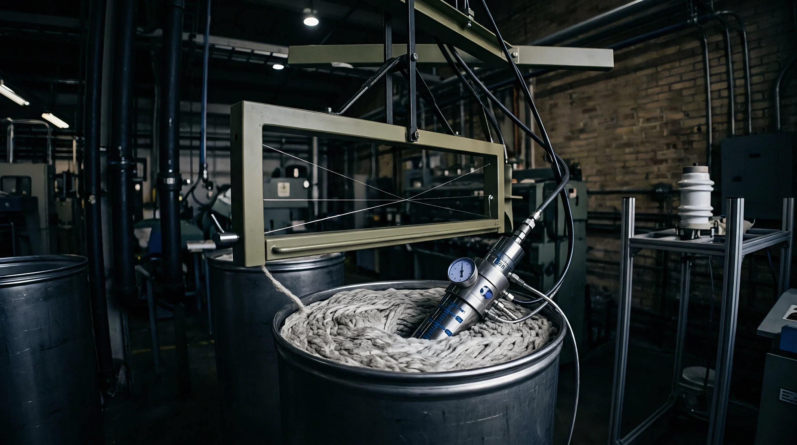
Establishing traceable measurement standards requires building dedicated calibration fixtures capable of simulating vessel conditions. Bench testing using hand pumps provides only static hydrostatic verification at ambient room temperature, failing to challenge transducer response under turbulent, elevated-temperature environments. A valid dynamic calibration rig matches the fluid dynamics and thermal pressures found in industrial dyehouses.
A closed-loop test loop constructed from 316L stainless steel provides an appropriate calibration environment. The loop features an inline electrical heating element, a high-head magnetic drive pump, and a high-speed rotating interrupter valve designed to generate controlled hydraulic pressure pulses up to 100 hertz. An uncalibrated sensor bolts directly opposite a water-cooled reference piezoelectric sensor traceable to international pressure standards.
- Thermal regulation subsystem maintains testing fluids up to 140 degrees Celsius using closed-loop PID control loops to mirror production heating rates.
- Pulsing mechanism uses a variable-speed perforated disc valve to create reproducible, square-wave pressure transients from 5 to 80 kilopascals above base pressure.
- Secondary injection port introduces textile auxiliary chemistries into the test fluid to evaluate surfactant and defoamer impacts on diaphragm responsiveness.
- High-speed data acquisition hub records dual-channel voltage outputs at sample rates exceeding twenty kilosamples per second per channel.
Testing sensors across multiple temperatures reveals hidden thermal hysteresis. As calibration rigs step from 25 degrees Celsius up to 135 degrees Celsius and return to ambient, many silicon-on-insulator piezoresistive sensors follow divergent voltage curves. The difference between heating and cooling output spans can exceed four percent of full-scale reading.
When technicians calibrate sensors solely during warming phases, production cooling steps run blind, risking fabric crush marks during cold rinse flushes.
Water quality within the test rig requires tight surveillance. Mineral scale deposition onto diaphragm surfaces during high-temperature cycles changes effective mass and damping ratios, introducing artificial calibration errors. Testing must run using demineralized water with electrical conductivity maintained below five microsiemens per centimeter.
Field installations frequently expose sensors to physical pipe stress from misaligned mounting flanges. Torque applied to sensor housing threads warps internal diaphragm mount rings, introducing offset errors that mimic line pressure. Calibrating sensors inside rigid test benches fails to capture these mechanical mounting strains.
Technicians must torque sensors into place using calibrated torque wrenches set precisely to supplier installation values.
Uncalibrated dynamic pressure loops ultimately degrade dyehouse yield, converting prime first-quality fabrics into discounted off-shade yardage through unnoticed liquor circulation failures.