Transient Hydraulic Pressure Dynamics during Thermal Ramps in Parallel Jet Dyeing Vessel Manifolds
Dynamic hydraulic header balancing and nitrogen expansion tank padding prevent nozzle cavitation and rope speed divergence during fast vessel thermal ramps.
Loop
Primary fluid delivery networks in multi-tube jet dyeing machinery distribute pressurized liquor from a central circulation pump into parallel nozzles. Fluid velocity inside the supply header ranges from 1.5 to 3.2 metres per second during normal processing. When the vessel temperature increases, fluid density and dynamic viscosity drop simultaneously, altering internal friction factors across every branch connection.
The static pressure at each nozzle inlet depends directly on head losses accumulated along the length of the main manifold pipe.
Header pipe geometry determines initial fluid split balance across parallel channels. A standard six-tube jet dyeing vessel utilizes a tapered supply manifold with internal diameters diminishing from 150 millimetres at the pump outlet to 80 millimetres at the terminal tube connection. Friction drops flow rates.
As water temperature climbs from 80 °C to 130 °C, the dynamic viscosity of water decreases from 0.355 to 0.217 centipoise. Lower viscosity elevates the Reynolds number inside the pipe network, shifting fluid movement deeper into the turbulent regime. This turbulence alters friction loss coefficients across elbows, tees, and venturi reductions.
Frictional pressure losses along stainless steel piping are calculated using the Darcy-Weisbach equation. When temperature increases during a 2.5 °C per minute thermal ramp, fluid density decreases from 971.8 kilograms per cubic metre at 80 °C to 934.6 kilograms per cubic metre at 130 °C. The combination of lower density and reduced viscosity changes fluid momentum at each header junction. Branch pipes nearest the main pump inlet experience transient pressure surges, while downstream branches lose net driving head.
Fabric ropes running in downstream tubes slow down when fluid velocity drops below required mechanical transport thresholds.
Hydraulic instabilities during heat exchanger cycles manifest as distinct physical failure modes across parallel vessel branches:
- Header Pressure Divergence occurs when thermal expansion and friction shifts cause unequal static head pressure across parallel nozzle inlets, resulting in varied liquor flow rates between individual vessel tubes.
- Rope Deceleration Events appear when localized line pressure drops below 1.2 bar, reducing the mechanical driving force inside the venturi tube and causing fabric gathering in the storage J-box.
- Thermal Expansion Surges occur when rapid heating expands the liquor volume faster than external expansion tanks absorb fluid, generating pressure pulses that destabilize pump impeller intake.
- Differential Flow Shear develops when adjacent nozzles operate at different fluid velocities, creating variable friction forces across delicate synthetic fabric surfaces during high-temperature processing.
Frictional pressure loss across distribution headers scales with fluid velocity squared. Equalizing header friction loss across every parallel branch preserves uniform liquor volume and prevents streak formation during rapid thermal transitions.
Cavitation
Fluid vaporization inside high-velocity nozzle throats occurs when static pressure falls below liquid saturation pressure during rapid temperature increases. High-temperature jet dyeing vessels operating at 130 °C carry a saturation vapor pressure of approximately 2.70 bar absolute. If the local static pressure inside a venturi throat drops below this threshold due to fluid acceleration, water vapor bubbles form instantly.
These vapor bubbles collapse downstream when static pressure recovers, generating localized hydraulic shock waves with peak pressures exceeding 50 bar.
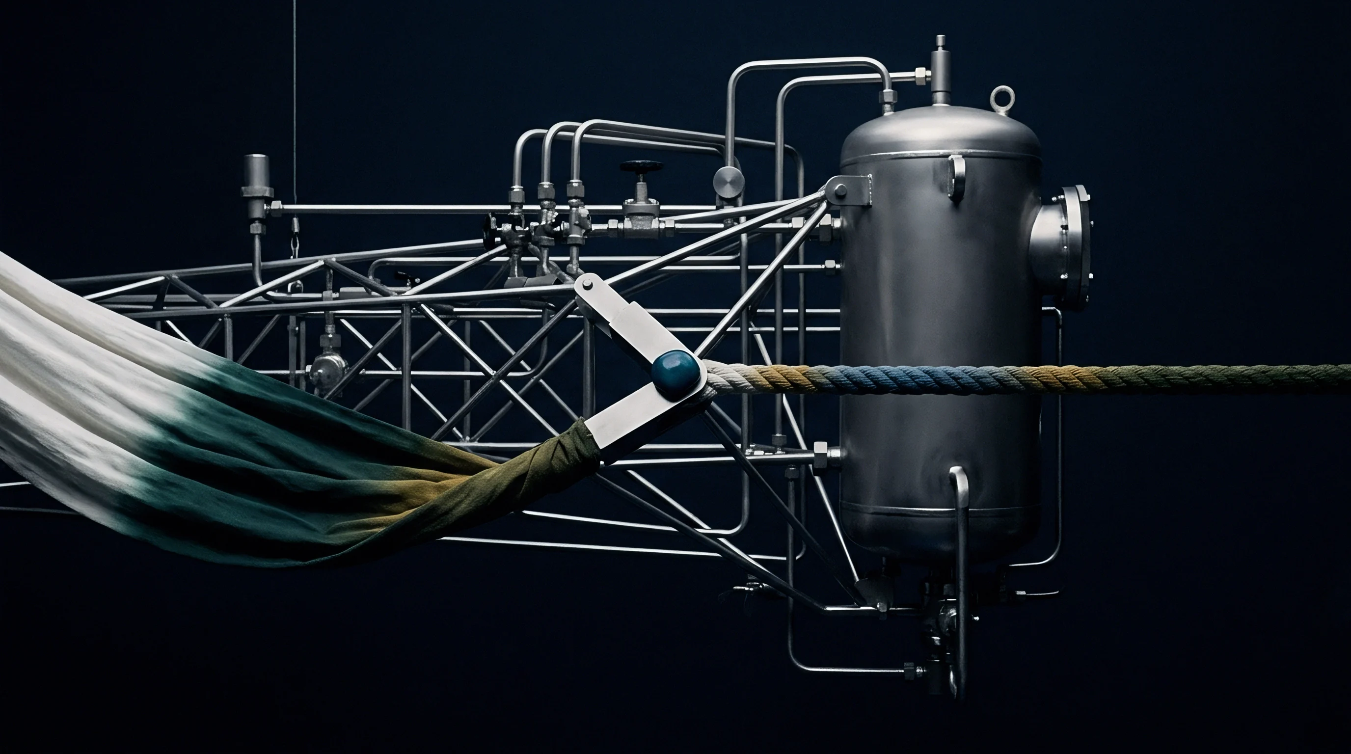
Vapour Bubble Formation in Venturi Throats
Saturated water at elevated temperatures undergoes rapid phase change under localized pressure drops created by high nozzle velocities. Liquid velocity inside a 40-millimetre venturi throat reaches 8.5 metres per second at maximum circulation pump output. Applying Bernoulli’s principle reveals that high kinetic energy inside the throat creates a proportional drop in static pressure.
When heating ramps push bulk liquor temperatures toward 135 °C, the saturation vapor pressure climbs to 3.13 bar absolute. Fluctuation in pump inlet pressure triggers immediate localized boiling inside the nozzle assembly.
An internal pipe static pressure above 3.2 bar at 130 °C prevents localized vaporization within primary distribution loops.
Pressure drops create bubbles. Continuous implosion of vapor cavities erodes internal stainless steel nozzle surfaces and destabilizes fluid propulsion. The fabric rope passing through the venturi experiences sudden loss of driving force when vapor pockets replace liquid mass.
Fabric movement becomes erratic. This unsteady rope motion leads to mechanical piling, knotting, and surface abrasion on sensitive polyester micro-denier fabrics.
Pump Suction Limits and Head Requirements
Net positive suction head margin collapses when main circulating liquor reaches operating temperatures above 120 °C. Main circulation pumps require a minimum net positive suction head to prevent cavitation at the impeller eye. During thermal ramps, expansion tank air padding or nitrogen cushion pressure maintains system static pressure above liquid vapor pressure. If air pad pressure control lags behind the heat exchanger thermal profile, net positive suction head available drops below the pump manufacturer threshold of 4.5 metres.
| Liquor Temp (°C) | Vapor Pressure (bar abs) | Minimum Vessel Static Pressure (bar) | Throat Static Pressure at 8 m/s (bar) | Cavitation Risk Assessment |
|---|---|---|---|---|
| 80 | 0.47 | 1.50 | 1.18 | Stable operation |
| 100 | 1.01 | 2.00 | 1.52 | Negligible risk |
| 120 | 1.98 | 2.80 | 2.12 | Moderate transient risk |
| 130 | 2.70 | 3.50 | 2.62 | Critical cavitation boundary |
| 135 | 3.13 | 3.80 | 2.88 | Active vaporization zone |
System pressure drops fast. Cavitation destroys pump impellers. Sustained localized boiling inside nozzle assemblies erodes internal metal surfaces, causes erratic fabric rope transport, and generates unrepairable streak defects across entire polyester dye lots.

Thermal
Temperature ramps between 80 °C and 135 °C induce rapid fluid volume changes and density shifts within closed pressurized dyeing circuits. A 6000-litre capacity jet dyeing vessel filled at an initial liquor-to-goods ratio of 1:8 experiences volumetric fluid expansion of nearly 240 litres during heating to 135 °C. Closed system design requires precise dynamic control of excess volume to prevent uncontrolled pressure spikes across distribution manifolds.
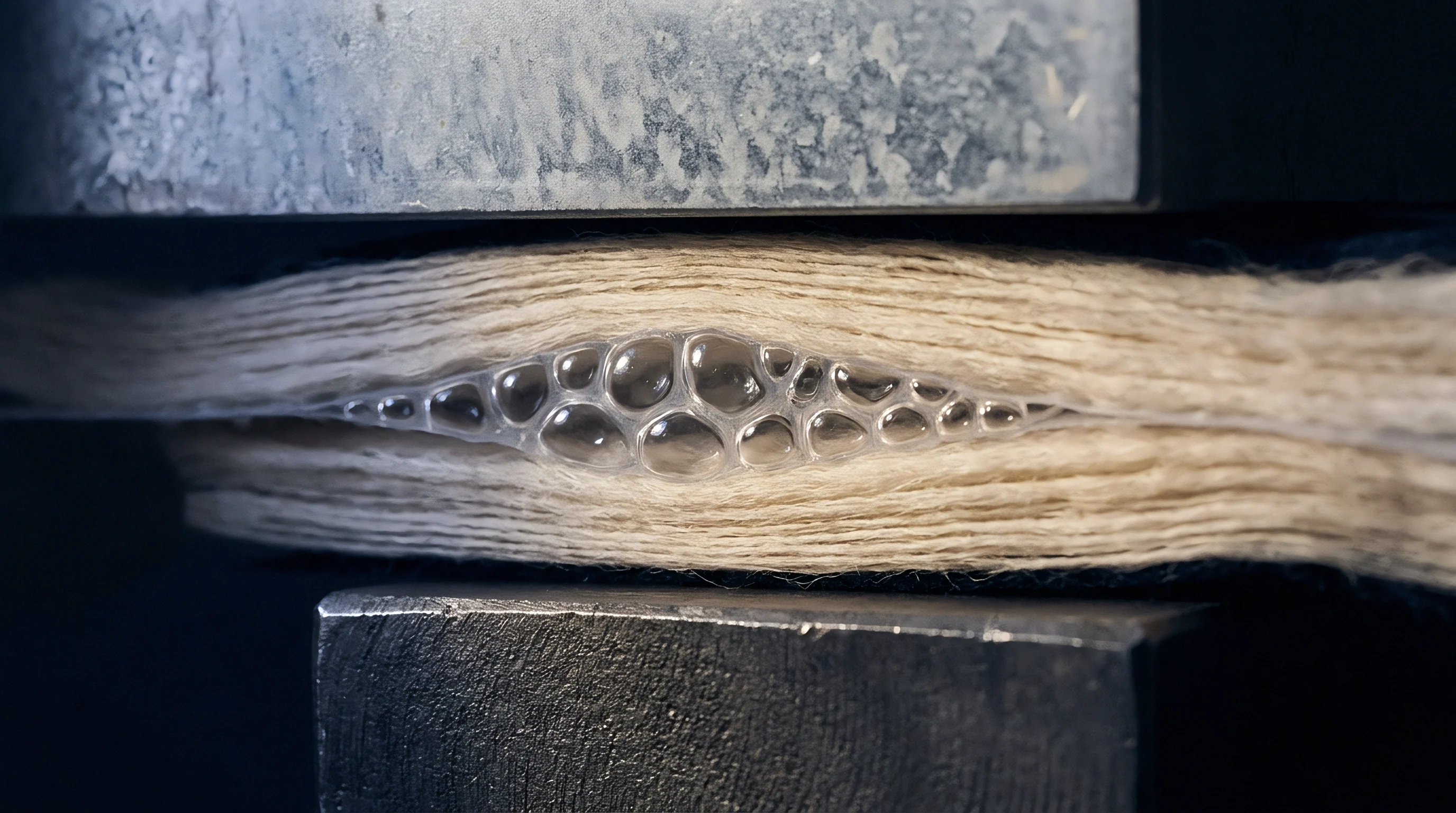
Volumetric Expansion and Fluid Density Changes
Water expands by approximately four percent when heated from room ambient up to high temperature dye processing thresholds. Thermal expansion alters internal vessel liquor levels and displaces air from the main expansion tank. In parallel vessel manifolds, fluid displacement creates transient counter-pressures against incoming pump discharge flows.
Fast thermal ramps of 3.0 °C to 3.5 °C per minute accentuate volumetric displacement speed, forcing pressure control valves to cycle rapidly.
High heat changes viscosity. Hot liquor expands quickly. Managing volume surges requires a defined operational sequence during high-temperature processing:
- Calculate total system liquor volume including heat exchanger tubes, main pump body, distribution headers, and vessel sump.
- Determine liquor thermal expansion coefficients at 1.0 °C per minute temperature increments up to 135 °C.
- Adjust expansion tank nitrogen bladders or top-pad air pressure to absorb displaced fluid volume without triggering relief valves.
- Monitor main pump inlet gauge pressure continuously during heating cycles to detect instant hydraulic collapse.
ISO 105-J03 total color difference limits below 0.8 DEcmc require strict cross-tube liquor volume balance throughout high-temperature ramps.
Steam pressure spikes instantly. Heat exchanger tube expansion generates mechanical stress on manifold flanges. Rapid heat transfer across heat exchanger plates generates localized thermal gradients inside the liquor stream, causing temporary density stratification inside long horizontal manifold headers.
Equipment vendors frequently claim that minor shade variances across parallel tubes stem from fabric structure inconsistencies rather than temporary hydraulic imbalances during heat exchanger steam cycles.
Sway
Flow volume imbalances between parallel vessel branches alter individual fabric rope speeds and nozzle driving forces during heating cycles. In a four-tube or eight-tube jet dyeing vessel, identical liquor volume distribution across every tube ensures equal dye exhaustion rates and uniform mechanical treatment. Thermal ramps disrupt this equilibrium because fluid flow paths exhibit minor physical length and resistance variations.
A branch with slightly lower fluid resistance draws a higher percentage of pump discharge during density transitions.
Multi Tube Flow Imbalance Mechanics
Differential pressure drops across individual distribution branches create uneven fluid distribution when total circulation pump output varies. Branch line pressure differences as small as 0.15 bar lead to a ten percent variance in nozzle liquor throughput. Higher flow velocity in one tube accelerates fabric rope turnover, increasing the frequency of fabric passage through the nozzle.
The rope in the lower-flow tube travels slower, receiving fewer liquor contacts per unit time during critical dye fixation windows.
| Tube Identifier | Branch Static Pressure (bar) | Nozzle Flow Rate (L/min) | Rope Velocity (m/min) | Crease Mark Index (1-5) |
|---|---|---|---|---|
| Tube 1 (Pump Inlet) | 2.85 | 420 | 280 | 1.2 (Clear) |
| Tube 2 | 2.80 | 410 | 272 | 1.4 (Clear) |
| Tube 3 | 2.72 | 395 | 260 | 2.1 (Slight) |
| Tube 4 (Terminal) | 2.60 | 370 | 242 | 3.8 (Severe) |
Fabric speed drops suddenly. Nozzle forces drive fabric. Variable linear speed between ropes alters color shade yield on synthetic blend knits.
When dyeing textured polyester with disperse dyes, the rate of dye uptake increases exponentially between 110 °C and 130 °C. Unequal circulation rates during this dynamic window cause batch shade variance between parallel tubes, leading to unlevel bulk dyeing rolls.
Crease Formation in Synthetic Knits
Heavy polyester knitted structures folded tightly in jet transport tubes develop permanent running creases when liquor flow fails to lubricate fabric folds during heating. Smooth rope propulsion relies on continuous liquor pillowing inside the nozzle and transport tube. When dynamic pressure drops in a specific manifold branch, fluid volume inside that transport pipe falls below critical flotation thresholds.
Maintaining uniform liquor volume across parallel tubes guarantees consistent mechanical fabric propulsion.
Crease marks appear quickly. Fabric folds rub under heavy tension against internal tube walls. Thermal ramps near the polyester glass transition temperature of 85 °C soften synthetic fibers.
Mechanical creasing occurring at this precise temperature zone heat-sets sharp longitudinal lines into the fabric length that cannot be removed by stenter frame post-finishing.
Balancing parallel manifold branches requires systematically executing a continuous verification routine:
- Branch Pressure Balancing requires installing calibrated orifice plates at every branch flange to equalize frictional flow resistance under peak pump discharge rates.
- Rope Speed Monitoring uses external optical rotation sensors on guide rollers to verify that linear fabric velocity stays within a five percent band across all parallel tubes.
- Nozzle Gap Calibration ensures precision micrometric adjustment of variable venturi throat areas to maintain equal fluid velocity despite minor line pressure variations.
- Liquor Level Verification maintains correct liquid volumes inside individual J-boxes to eliminate localized foam buildup and suction drag differences.
Commercial purchase contracts specifying ASTM D3776 weight tolerances and ISO 12945 pilling resistance default to buyer rejection rights when parallel branch pressure fluctuations create severe rope abrasion marks.
Calibration
Pressure transducer placement and signal processing delays obscure real-time hydraulic fluctuations inside high-temperature manifold headers. Standard industrial pressure transmitters mounted on external siphon loops feature response response delays ranging from 250 to 800 milliseconds. Rapid dynamic pressure transients occurring within 50 milliseconds pass completely undetected by central programmable logic controllers, giving dyehouse operators a false indication of hydraulic stability.
Sensor Response Delays and Transducer Placement
Electronic pressure measuring instruments installed behind isolating siphon tubes experience significant thermal inertia during fast temperature ramps. Siphon tubes protect delicate transducer diaphragms from hot process steam and aggressive chemicals. However, trapped liquid columns inside siphon coils damp dynamic pressure waves, reducing recorded peak amplitudes.
Transducers drift under heat. Measured pressure figures reflect smoothed average system state rather than true transient peak and trough pressures.
| Transducer Location | Siphon Length (mm) | Response Delay (ms) | Thermal Drift Error (%) | Transient Peak Under-Report (bar) |
|---|---|---|---|---|
| Main Header Direct | 0 (Flush Diaphragm) | 15 | 0.8 | 0.05 |
| Header Short Siphon | 150 | 220 | 0.3 | 0.35 |
| Branch Line Siphon | 300 | 550 | 0.2 | 0.68 |
| Expansion Tank Loop | 500 | 850 | 0.1 | 0.92 |
Water turns to steam. Flow balancing prevents shading. Installing flush-mounted sanitary diaphragms with cooling elements minimizes signal delay while protecting sensor electronics from high thermal stress.
Differential Pressure Control and Valve Actuation
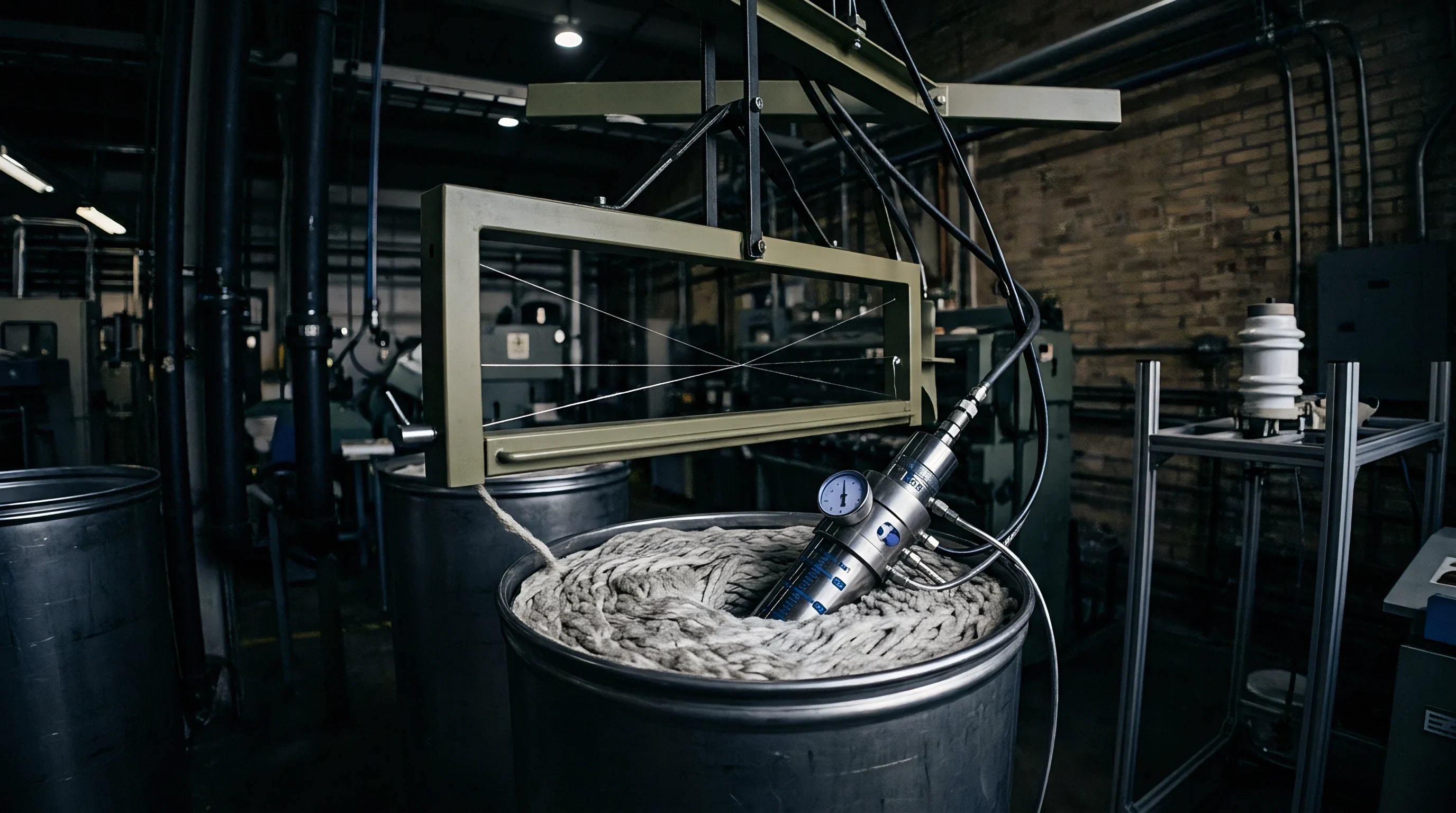
Automatic flow regulation valves matching pump output to vessel pressure require precise feedback tuning to prevent hunting during heat exchanger steam pulses. Control loops using proportional-integral-derivative algorithms struggle when liquor density and viscosity vary continuously during thermal ramps. If derivative gains are set too high, control valves oscillate rapidly, inducing severe secondary pressure waves across parallel vessel manifolds.
Rapid steam injection destabilizes differential pressure across parallel venturi nozzles during high-temperature ramps.
Precise purchasing specifications require clear documentation to qualify machine hydraulic stability before equipment commissioning:
- Transducer Response Criteria defines maximum allowable signal latency below 50 milliseconds for main manifold pressure monitoring loops.
- Manifold Balancing Certificate requires factory water-test documentation proving flow distribution balance within a two percent variance across all nozzle outlets.
- NPSH Verification Log mandates continuous net positive suction head monitoring curves across full temperature cycles from 20 °C to 140 °C.
- Ramp Speed Audit Protocol establishes empirical testing procedures for dynamic pressure stability at heating rates up to 3.5 °C per minute.
Dyehouses continue to debate whether active digital manifold throttling valves offer sufficient dynamic stability to justify their high maintenance costs compared to passive orifice balancing rings.
Discharge
Overpressure relief valve activations during dynamic thermal ramps vent excess liquor volume, causing dye liquor ratio shifts and shade depth deviations. Safety valves set to discharge at 4.5 bar gauge open when thermal fluid expansion and steam injection spikes exceed combined header volume capacity. Unexpected pressure relief drops internal vessel static pressure instantly, causing bulk flash boiling throughout the heat exchanger and distribution manifold.
Loss of liquor mass alters the operational liquor-to-goods ratio from an intended 1:8 down to 1:6.5 in extreme venting incidents. Concentrated dye chemistry accelerates dyestuff exhaustion onto fabric surfaces, causing severe unlevelness, streaking, and batch-to-batch color variation. Automated dosing systems cannot compensate for unmeasured dye liquor loss through safety relief lines.
Thermal energy escapes alongside liquid mass, extending heating cycle durations and inflating utility costs per kilogram of finished fabric.
Uncontrolled pressure spikes that blow relief valves deplete specialized leveling agents, shift shade depth by up to two DEcmc units, and waste expensive thermal energy through the drainage channel.