Equalizing Parallel Nozzle Pressure for Uniform Jet Dyeing
Equalizing parallel nozzle pressure requires balanced manifold geometry and dynamic trim adjustment to eliminate strand speed variance and tube-to-tube shade defects.
Hydraulics
Dye liquor flow through multi-tube jet machines depends on how the main circulation pump output divides into secondary piping networks supplying individual fabric ropes. When fluid divides across parallel paths, slight geometric or frictional differences between lines alter the pressure distribution at each nozzle inlet. Centrifugal pumps deliver a specific volumetric rate against system head loss based on the system resistance curve.
If one processing tube exhibits higher resistance due to pipe bends, internal roughness, or accumulated lint, liquor volume diverts toward lines offering lower resistance.
Head loss along secondary feed lines operates according to the Darcy-Weisbach equation, where friction factor, pipe length, internal diameter, and fluid velocity define total pressure drop. In high-temperature wet processing equipment operating between 98°C and 130°C, dye liquor density and dynamic viscosity decrease significantly compared to ambient conditions. Water at 130°C exhibits a kinematic viscosity roughly one-third of its value at 20°C, increasing the Reynolds number and driving flow deeper into the turbulent regime.
Under highly turbulent conditions, minor geometric variations at pipe tees or elbows generate amplified pressure drops across adjacent supply lines.
A differential nozzle pressure exceeding 0.15 bar across parallel tubes generates measurable shade variation in light-density knitted fabric runs under ISO 105-J03 color evaluation.
In a four-tube jet vessel operating with an unbalanced manifold, pressure at nozzle entry points can vary by up to 0.4 bar between the first branch and the final dead-end branch. This pressure variance directly alters the velocity of the fluid jet exiting the venturi orifice. Fabric rope movement depends entirely on the mechanical drag exerted by the high-velocity fluid stream.
When fluid velocity drops in one tube, fabric strand speed decreases correspondingly, increasing dwell time inside the storage chamber and altering liquor exchange cycles per minute.
| Tube Identifier | Inlet Gauge Pressure (bar) | Fluid Jet Velocity (m/s) | Strand Velocity (m/min) | Exhaust Rate (%/min) | Shade Delta E (ISO 105-J03) |
|---|---|---|---|---|---|
| Tube 1 (Primary Split) | 2.45 | 14.2 | 385 | 2.15 | 0.82 (Off-Tone) |
| Tube 2 (Mid Stream A) | 2.20 | 13.4 | 360 | 1.98 | 0.24 (Standard) |
| Tube 3 (Mid Stream B) | 2.15 | 13.2 | 355 | 1.92 | 0.18 (Standard) |
| Tube 4 (Terminal Branch) | 1.90 | 12.1 | 320 | 1.65 | 0.94 (Off-Tone) |
Varying exhaust rates between parallel fabric strands lead to shade inconsistencies across a single dye lot. Fabric passing through high-pressure nozzles experiences faster dye molecule transport from bath to fiber surface, accelerating strike rates during critical fixation windows. Pressure drops propagate backward quickly through the line.
When shade depth differs between ropes within the same batch, shade pass rates fall, forcing costly addition cycles or stripping procedures. Uncorrected pressure differentials cause tube-to-tube shade mismatches that force re-dyeing operations, degrading tensile strength and doubling energy expenditure per kilogram of finished fabric.
Venturi
Internal geometry inside jet nozzles accelerates dye liquor by forcing circulation volume through a constricted throat section, converting static pressure head into dynamic velocity head. According to Bernoulli principle, fluid static pressure drops as velocity increases within the restricted throat. This differential pressure creates kinetic suction that draws the endless textile strand through the nozzle transport tube without mechanical drive rolls.
When parallel nozzles possess slight variations in throat diameter or internal gap settings set by mechanical alignment, the fluid velocity profile shifts dramatically across lines.
Fabric rope transport kinetics depend directly on fluid shear stress applied at the boundary layer between liquid stream and textile substrate. Lightweight warp knits made from micro-denier synthetic fibers require low nozzle pressure settings around 1.0 to 1.5 bar to prevent surface pilling or filament breakage, where unmitigated shear forces can damage delicate fibers. Heavy weight tightly woven cotton or blend fabrics demand operating pressures reaching 2.8 to 3.5 bar to maintain rope movement and overcome chamber friction.
If nozzle gap settings across parallel lines vary by as little as 0.2 millimeters, fluid jet energy and rope acceleration rates diverge immediately.
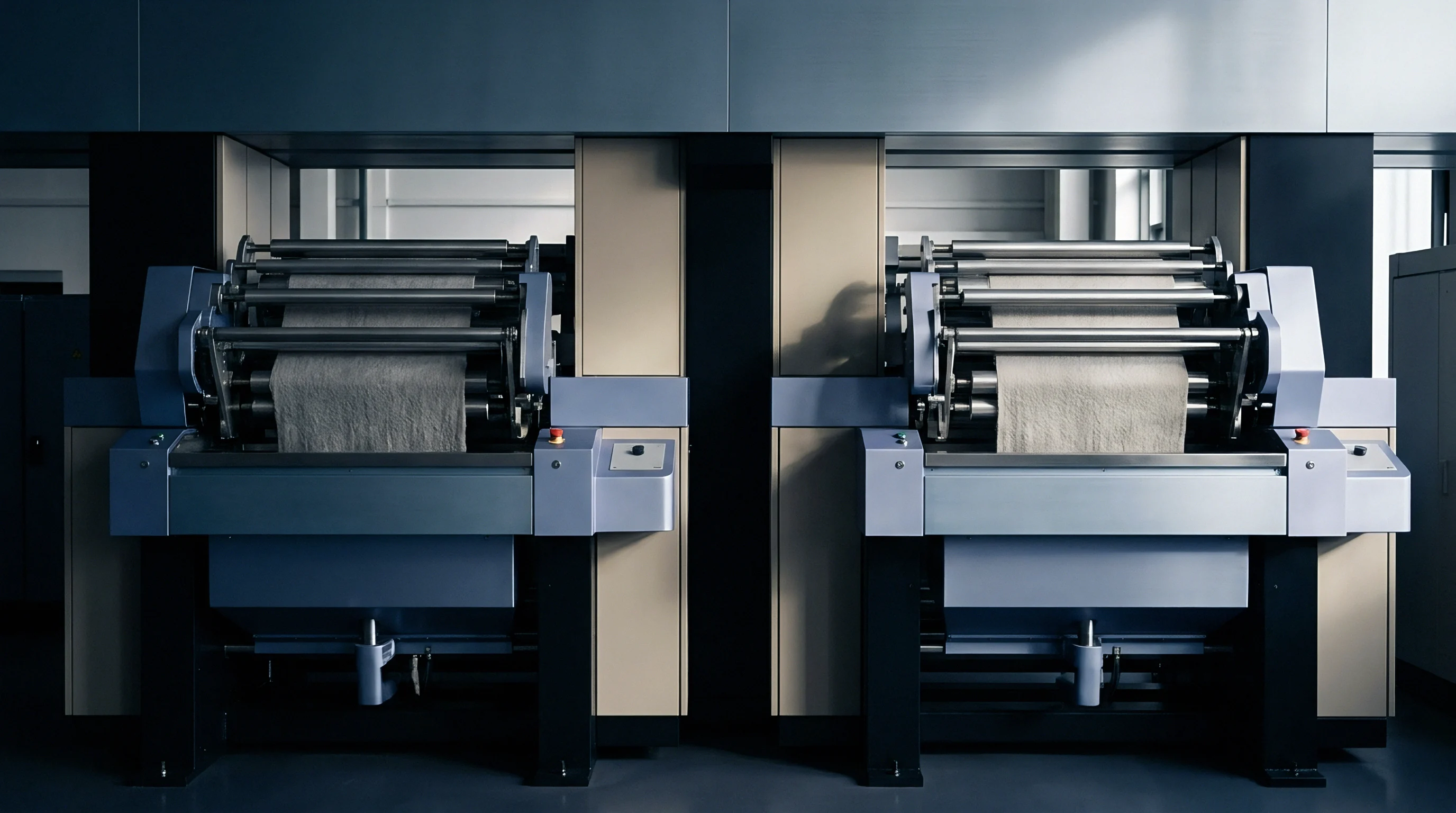
Nozzle Operational Failures in Multi Tube Systems
- Asymmetric Throttle Wear occurs when abrasive dye bath additives or particulate dye agglomerates erode internal nozzle surfaces unequally over extended production cycles.
- Lint Accumulation at Orifice creates localized flow blockages that increase backpressure upstream while reducing exit fluid velocity around the fabric rope.
- Mechanical Gap Misalignment arises when manual adjustment rings are set without precision feeler gauges, producing unequal cross-sectional flow areas across parallel lines.
- Cavitation Erosion damages internal venturi walls when localized static pressure drops below dye liquor vapor pressure, forming imploding micro-bubbles that pit stainless steel surfaces.
Shade banding is frequently attributed to variations in yarn dye uptake, though manufacturing tolerances in nozzle orifice diameters can equally create unequal jet velocities across lines.
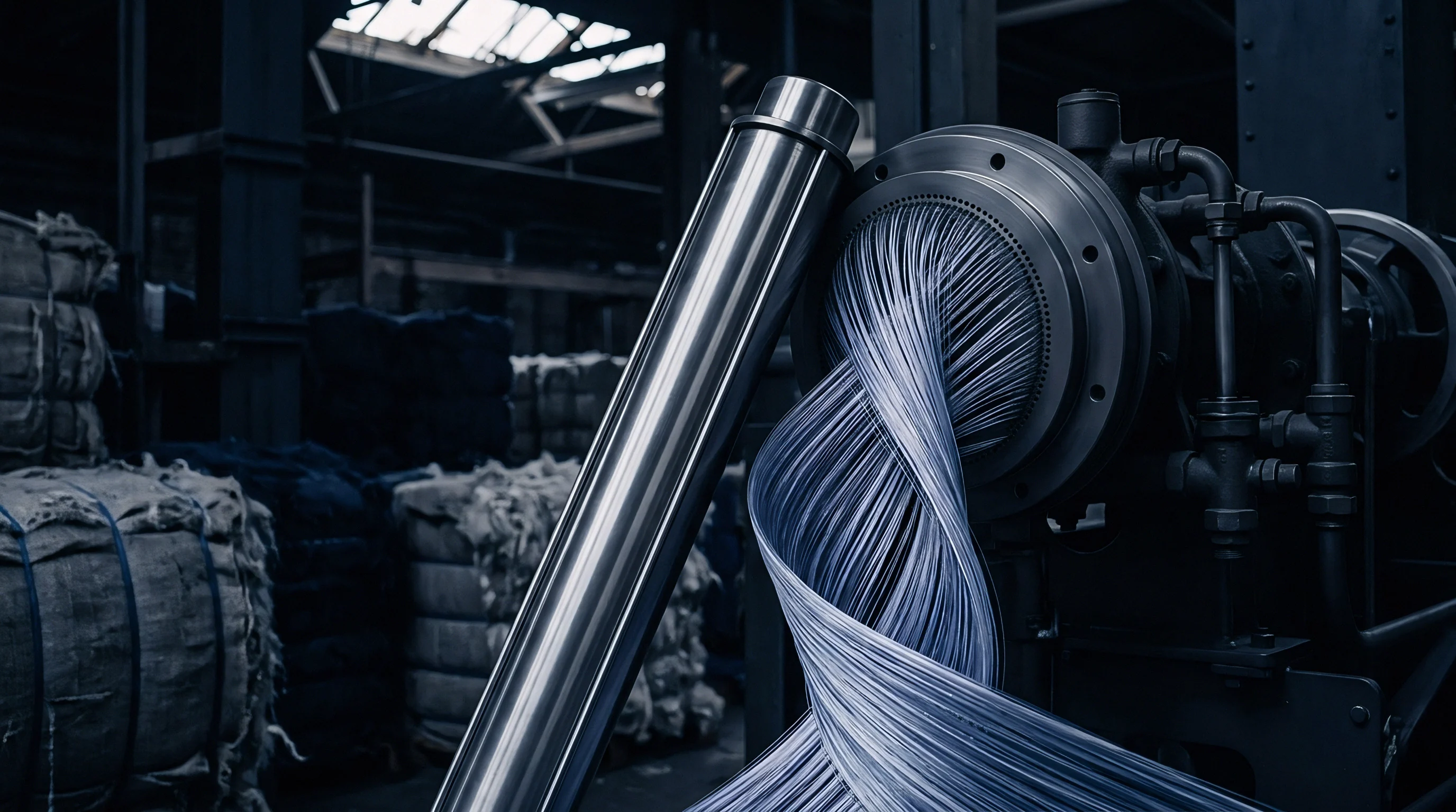
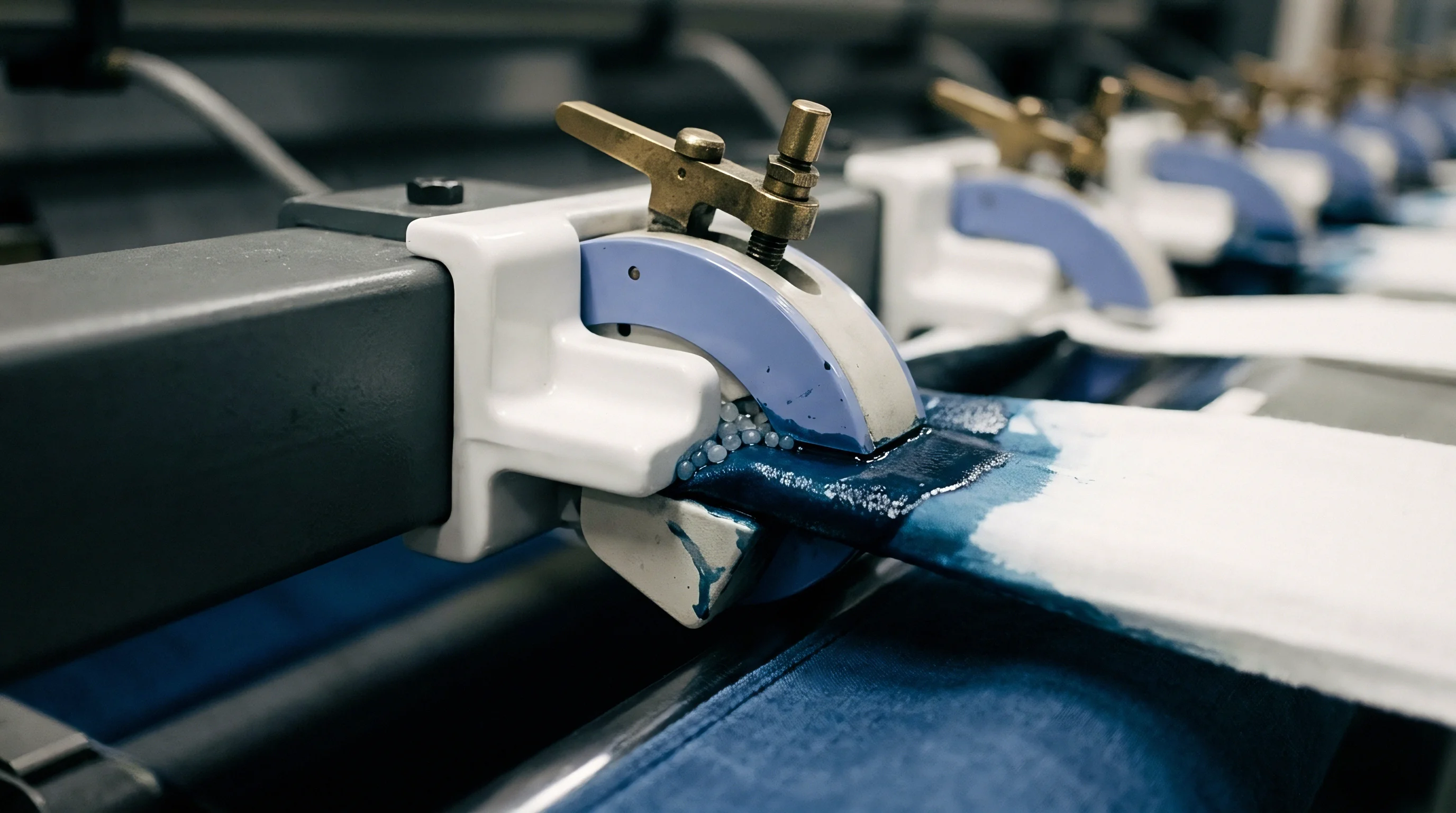
Manifold
Supply pipe design establishes baseline pressure distribution across parallel dye jets before liquor reaches individual nozzle assemblies. Standard straight-header supply manifolds feature a single main inlet feeding perpendicular branch lines sequentially. Fluid traveling along a straight header encounters momentum conservation effects, where static pressure increases toward the closed terminal end as fluid velocity decreases.
This phenomenon creates higher static inlet pressure at the final tube branch compared to intermediate branches, contradicting simple friction loss models that predict steady pressure decay along pipe runs.
How Does Header Geometry Affect Tube Line Pressure?
Pipe layout geometry dictates whether fluid delivery balances passively or requires constant manual intervention. Reverse-return manifold configurations equalize total flow path length for every branch line, ensuring identical friction losses across all parallel routes. Fluid entering the first tube branch returns along an auxiliary header that collects discharge from all tubes, equalizing line resistance.
Because piping friction varies with temperature, balanced tree structures split the main flow into symmetrical pairs, dividing line volume through identical branch geometry until reaching individual jet nozzles.
| Manifold Design Type | Static Pressure Variance Across Tubes (%) | Flow Rate Discrepancy (L/min) | Thermal Distribution Gradient (°C) | Capital Piping Cost Index |
|---|---|---|---|---|
| Sequential Straight Header | 14.2 | 28.5 | 3.8 | 1.00 |
| Tapered Main Supply Header | 8.6 | 16.2 | 2.1 | 1.35 |
| Reverse-Return Loop Header | 2.1 | 4.1 | 0.6 | 1.80 |
| Symmetrical Balanced Tree | 1.2 | 2.2 | 0.3 | 2.15 |
Tapered header manifolds reduce cross-sectional area progressively downstream of each branch tee. As fluid volume exits into secondary feed lines, header diameter contracts to maintain constant linear fluid velocity along the main supply path. Preserving momentum prevents static pressure buildup at terminal caps, as pipe diameters downstream of a distribution split decrease in cross-sectional area to preserve fluid momentum across all secondary branches.
Incorporating ISO 13934 physical tensile retention thresholds into wet processing specs forces mills to rebalance manifold delivery before running tight warp knits.
Transducer
Monitoring dynamic pressure balance across parallel jet nozzles requires high-precision instrumentation capable of operating within corrosive chemical baths at elevated temperatures. Piezo-resistive differential pressure sensors mounted with flush diaphragm seals protect sensitive electronic elements from aggressive dye chemicals, caustic soda, and high hydrogen ion concentrations. Sensor tap points installed immediately upstream of each nozzle entrance record real-time static pressure ~ which can otherwise mask dynamic variance across lines ~ and transmit 4-20 milliamp signals to central programmable logic controllers.
Maintaining balance requires active trim. Digital pressure readings must undergo continuous temperature compensation inside the control system because thermal expansion alters chemical bath density. Differential pressure measuring protocols require structured zeroing operations prior to heating cycle activation.
- Fill jet vessel with water and levelling auxiliary chemicals to standard operational sight-glass level.
- Isolate fabric rope transport mechanisms while engaging main circulation pump at thirty percent maximum frequency drive output.
- Bleed air entrapment pockets from all sensing lines and diaphragm seal mounting blocks via manual drain cocks.
- Record baseline static pressure values across all parallel transducer channels under ambient thermal conditions.
- Ramp dye bath temperature to one hundred thirty degrees Celsius at two degrees per minute while recording pressure drift parameters.
- Apply electronic zero offsets inside controller software to eliminate thermal drift variance before introducing dye concentrate.
Dynamic pressure balancing always prioritizes equal fluid delivery over matching mechanical valve stem indicator positions across parallel lines.
Data logged by differential pressure instruments provides primary verification during shade audit investigations following batch rejections. Compliance with ISO 105-X12 fastness protocols requires documented validation of differential pressure calibration records prior to issuing bulk shade sign-offs.
Balance
Equalizing liquor delivery across parallel nozzles demands active mechanical regulation coupled with real-time feedback loop control. Globe valves equipped with micrometer position indicators or diaphragm control valves installed on individual feed lines allow fine tuning of fluid flow resistance. Adjusting valve trim alters local head loss, compensating for structural piping asymmetries or minor nozzle manufacturing variations.
Manual balancing routines performed while running dry fabric or clear water fail to replicate dynamic hydrodynamic loads experienced during actual dyeing operations.
Fabric density, construction type, and rope volume alter total chamber hydraulic drag during circulation. A heavy terry toweling fabric carries substantial water weight out of the storage vessel, increasing drag inside the transport tube compared to a slick nylon taffeta. Interplay between fabric weight, strand velocity, and liquor pump speed requires systematic balancing adjustments for each distinct fabric quality group, as turbulence and potential impeller cavitation can degrade flow stability.
Unbalanced fluid kinetic energy inside multi-tube chambers produces differential strand speed that directly compromises dye liquor exhaust rate uniformity.
| Fabric Weight Range (GSM) | Fabric Structural Build | Target Strand Speed (m/min) | Nozzle Diameter (mm) | Main Pump Pressure (bar) | Individual Trim Valve Position (% Open) |
|---|---|---|---|---|---|
| 80 to 140 | Single Jersey / Tricot | 400 to 500 | 50 to 60 | 1.2 to 1.6 | Tube 1: 72% / Tube 4: 88% |
| 150 to 240 | Interlock / Poplin | 300 to 400 | 65 to 75 | 1.8 to 2.4 | Tube 1: 78% / Tube 4: 94% |
| 250 to 380 | French Terry / Twill | 200 to 300 | 80 to 90 | 2.5 to 3.2 | Tube 1: 85% / Tube 4: 100% |
Flow Equalization Decision Checklist
- Verify Mechanical Nozzle Dimensions using precision internal micrometers across all parallel tubes before installing fabric ropes.
- Measure Strand Circulation Speed on every rope using hand-held tachometers or automated optical sensor arrays to identify slow strands.
- Inspect Heat Exchanger Differential Pressure to confirm scale deposits are not restricting fluid volume prior to manifold split points.
- Adjust Secondary Trim Valves incrementally while observing differential pressure transducers until line readings match within a two percent tolerance window.
- Document Calibrated Valve Positions within machine recipe profiles to establish repeatable setup parameters for future fabric lots.
Whether automated motorized trim valves controlled by real-time optical strand counters can fully eliminate manual balancing routines remains an open operational question among dyehouse technical directors.

Audit
Systematic qualification of multi-tube jet machines forms an indispensable component of dyehouse quality assurance programs. Physical inspection routines begin with verifying manifold cleanliness, pipe wall thickness, and internal valve condition, as unbalanced tubes directly yield shade rejections. Accumulated chemical residues or oligomer deposits inside feed pipes restrict clear cross-sectional area, introducing unpredictable friction factors that disrupt calculated fluid balance formulas.
Regular chemical boil-outs using sodium hydroxide and hydrosulfite formulations clear internal surfaces, restoring baseline hydraulic characteristics across parallel pipe networks.
Machine Qualification and Commissioning Requirements
- Hydrostatic Pressure Testing validates structural integrity of manifold piping joints and valve seal packaging under one point five times maximum working pressure.
- Multi Channel Flow Verification records individual branch discharge rates using external ultrasonic flow meters clamped to external pipe runs.
- Thermal Mapping Protocol tracks temperature consistency across parallel supply lines during rapid heating and cooling cycles using calibrated thermocouples.
- Strand Speed Synchronization confirms fabric rope transport velocities across all processing chambers land within three percent of target setpoints.
Quality management systems rely on statistical process control to track shade variation between fabric ropes processed in different tubes of the same jet machine. Color spectrophotometers read dyeings from each strand under D65, A, and TL84 illuminants to calculate color difference values according to the CMC 2:1 formula. Batches demonstrating a delta E greater than 0.5 between ropes indicate unresolved pressure or flow imbalances inside the machine delivery system.
Technical audits mandate immediate machine isolation when tube-to-tube shade variation exceeds acceptable statistical limits, triggering thorough nozzle calibration, transducer recalibration, and trim valve adjustment before releasing equipment back into bulk production streams.