Dynamic Scaling Protocols for Lab Dip Translation in High-Capacity Jet Vessels
Lab dip recipes translate to high-capacity jet vessels by adjusting electrolyte concentrations for lower liquor ratios and extending cycle-matched dosing profiles.
Liquor
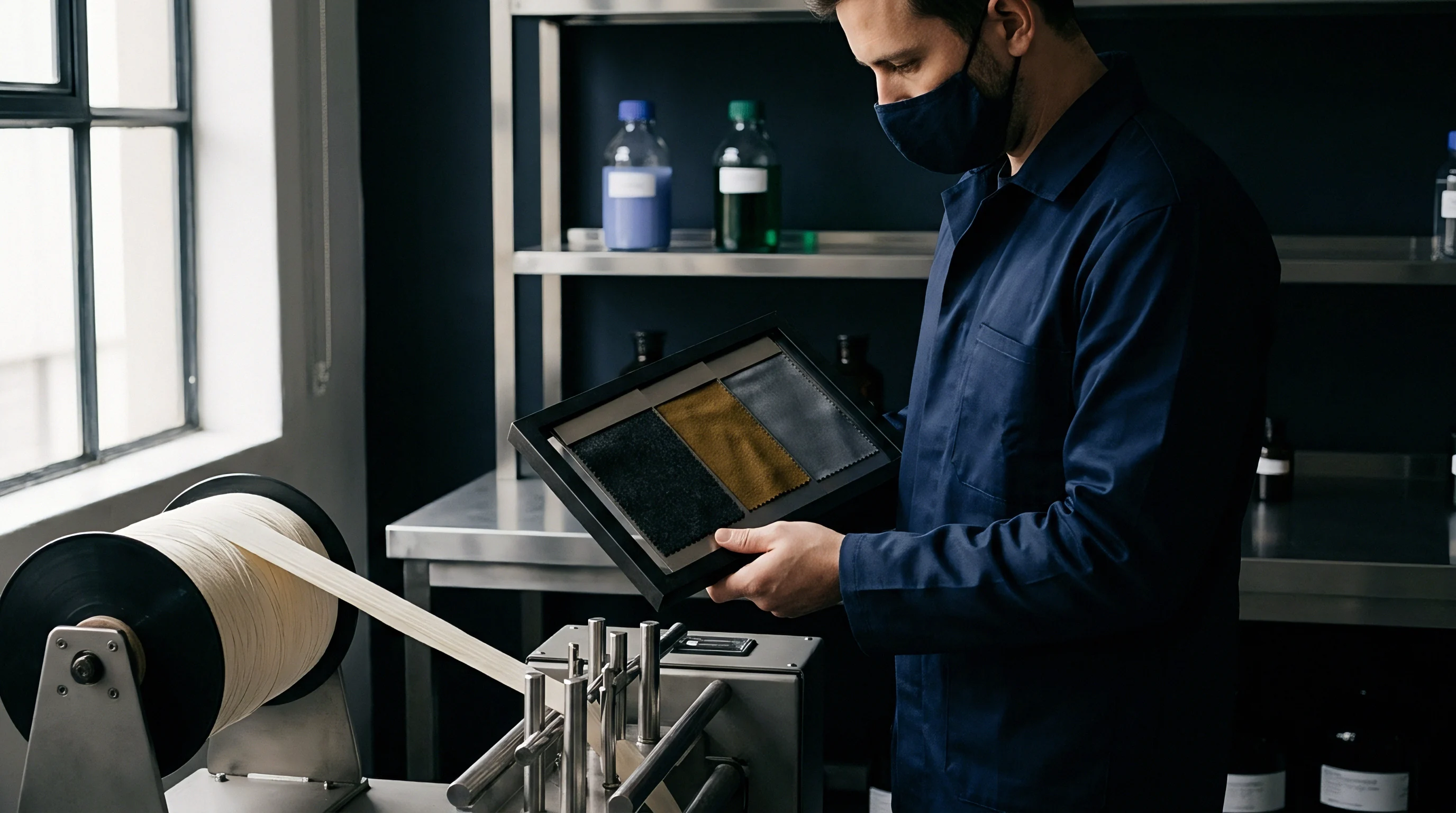
Standard laboratory beaker dyeing systems run at a 1:10 or 1:15 mass ratio between dry substrate and bath volume, whereas industrial jet production machinery operates between 1:5 and 1:7. Bath ratio shifts. This volumetric compression alters the concentration gradient of dissolved chemical species, shifting the thermodynamic equilibrium of colorant absorption.
Electrolyte additions calculated in grams per liter in a high-ratio lab beaker yield significantly higher total salt masses relative to fabric weight when transferred directly to a low-ratio jet vessel. Dyes exhaust early. At a 1:5 liquor ratio, the reduced volume of water surrounding the textile fiber accelerates exhaustion rates, causing rapid shade deposition on outer yarn surfaces before uniform penetration occurs throughout the fabric rope.
Substrate liquid pickup and boundary layer dynamics further compound the translation divergence. In laboratory beaker units, mechanical agitation continuously floods the loose fabric swatch with excess liquid, maintaining a saturated chemical boundary layer. In high-capacity jet vessels, the fabric rope absorbs a massive percentage of the total bath volume into its internal structure, leaving a minimal free-flowing liquid margin within the main transport tube.
This structural absorption reduces the effective bath volume available for chemical circulation, effectively lowering the operational ratio beyond nominal calculations.
A contract specifying ISO 105 C06 A2S color fastness to washing allows rejection of the lot when bath ratio variations shift the shade beyond a DE CMC 2:1 threshold of 0.8.
Adjusting lab recipes for bulk scale-up requires recalculating electrolyte concentrations on the basis of active bath volumes rather than absolute fabric weight. Dosing schedules for levelling agents, alkalis, and acids must account for the compressed liquid space to prevent premature exhaustion and localized strike marks. Dyehouse technicians frequently claim that laboratory recipe variations stem entirely from uncalibrated beaker pipettes rather than vessel boundary layer dynamics.
Velocity
Mechanical energy supplied by the venturi nozzle propels the textile rope through the transport tube while simultaneously circulating the bath chemistry. Rope speed governs levelness. Achieving level coloration across a 1000-kilogram fabric batch depends on the frequency with which each meter of the fabric loop passes through the nozzle zone during the exhaustion cycle.
Hydrodynamic Shear and Fabric Displacement
Internal pump impellers generate hydraulic force that accelerates the bath liquid through an adjustable venturi orifice. Nozzle pressure creates tension. High fluid movement forces the fabric rope through the main chamber while opening the yarn bundle to facilitate dye liquor transfer.
The physical friction generated within the nozzle tube varies with vessel geometry, total load weight, and nozzle diameter selection.
| Vessel Type | Nominal Capacity (kg) | Fabric Speed (m/min) | Bath Turnover Rate (cycles/min) | Nozzle Pressure (bar) | Rope Cycle Time (sec) |
|---|---|---|---|---|---|
| Laboratory Beaker | 0.05 | 0.0 | 12.0 | 0.00 | 0.0 |
| Pilot Jet Machine | 15.00 | 150.0 | 4.5 | 0.35 | 45.0 |
| Single-Tube Jet Vessel | 250.00 | 350.0 | 2.8 | 0.65 | 75.0 |
| Multi-Tube Jet Vessel | 1000.00 | 450.0 | 1.9 | 0.85 | 110.0 |
Cycle Time Matching across Scaled Vessels
Rope speed governs the interval required for one complete revolution of the textile loop inside the chamber. The venturi propels cloth. When a 1000-kilogram vessel runs four parallel fabric ropes, total cycle times often stretch to nearly two minutes per revolution.
If the dye exhaustion rate exceeds the fabric circulation speed, colorants fix unevenly along the length of the rope, producing longitudinal shade variation.
Translating laboratory recipes to high-capacity jet systems demands matching the bath turnover frequency to the rope loop cycle time. Increasing mechanical pump output elevates liquid circulation rates to balance extended rope transit times. Improper calculation of rope speed relative to pump turnover produces rope marks, horizontal banding, and permanent crease lines that reduce finished yield by up to twelve percent.
Kinetics
Thermal ramp rates in laboratory beaker machines routinely reach 3.0°C per minute, whereas 1000-kilogram production vessels rarely exceed 1.5°C per minute due to boiler pressure and heat exchanger surface area limits. Heat exchangers lag. This thermal disparity alters dye absorption kinetics across all temperature-dependent fixation phases.
Thermal Ramp Rates and Exhaustion Profiles
Gradual temperature increases stabilize the migration behavior of reactive and disperse dye combinations across dense fabric structures. Fast thermal ramps in laboratory dip units create an artificial exhaustion profile that fails when duplicated under slower industrial heating cycles. Prolonged thermal exposure in large production vessels extends the time colorants spend in the secondary exhaustion zone, altering total dye uptake.
Worked Scaling Model for Reactive Dyeing
Assume a 450-kilogram lot of 100% combed cotton jersey dyed with C.I. Reactive Blue 221, Reactive Red 141, and Reactive Yellow 84 at a target shade depth of 2.5% total colorant weight. The laboratory recipe utilizes a 1:10 liquor ratio with 50 g/L sodium sulfate and 15 g/L sodium carbonate, achieving fixation over a 60-minute holding phase at 60°C.
When transferring this recipe to a 450-kilogram jet vessel operating at a 1:5.5 liquor ratio, total bath volume drops from 4500 liters to 2475 liters. Maintaining a strict 50 g/L sodium sulfate concentration in the reduced bath volume requires 123.75 kilograms of salt, compared to 225 kilograms required under the laboratory 1:10 ratio. The total salt charge per kilogram of fabric drops from 50% to 27.5% on weight of fabric.
A 450-kilogram batch of cotton jersey processed at a 1:5.5 liquor ratio requires 123.75 kilograms of sodium sulfate to maintain an active bath concentration of 50 grams per liter.
Alkali dosing schedules must adjust to offset the compressed volume. Alkali causes fixation. Injecting 15 g/L sodium carbonate (37.125 kg total) into 2475 liters of water produces a rapid pH shift from 6.5 to 11.2 if added in a single dose.
Ramp rates double. To match laboratory exhaustion curves, the automated jet controller dosing profile expands into a linear-progressive curve: 10% alkali volume injected over 15 minutes, followed by 90% over 30 minutes.
The exact degree to which micro-turbulence within high-flow nozzles accelerates alkali diffusion inside dense cellulosic yarns remains an open area of inquiry among dyehouse fluid dynamics specialists.
Dispersal
Chemical additions in large-scale jet systems enter the primary circulation loop through a secondary dosing tank equipped with progressive metering pumps. Pumps meter chemicals. Direct manual additions used in laboratory beaker dyeing are impossible in pressurized bulk vessels.
Standard Operating Procedure for Machine Dosing Adjustments
Technicians follow a fixed sequence to transfer concentrated auxiliaries into the main vessel without shocking the dye bath.
- Fill the auxiliary dosing tank with soft water at a temperature matching the primary bath.
- Dissolve pre-weighed electrolyte or alkali charges using high-shear mechanical agitation for ten minutes.
- Program the progressive metering pump to execute a progressive curve over twenty-five minutes.
- Monitor main vessel differential pressure gauges to ensure steady circulation during chemical transfer.
- Flush secondary dosing lines with clean softened water immediately following transfer completion.
Dosing Curve Parameters for Levelling Control
Progressive addition schedules prevent local over-saturation at the nozzle intake port. Agitation dissolves salt. Selecting the correct dosing algorithm stabilizes the colorant distribution during critical exhaustion windows.
- Linear dosing schedules feed equal chemical volumes per unit time, suitable for low-affinity dye systems.
- Progressive dosing profiles deliver low initial quantities before exponentially increasing transfer rates, preventing rapid strike during early fixation.
- Deressive dosing methods inject high initial concentrations that gradually decay, applied primarily during acid dye levelling on nylon substrates.
Color yields drop. When scaling reactive dye recipes to low-volume jet vessels, slow progressive alkali addition prevents surface ring-dyeing far more effectively than elevated levelling agent concentrations.

Calibrations
Color matching spectrophotometers evaluate reflectance values across the visible spectrum to generate formulation predictions for production scale-up. Spectra reveal errors. Digital recipe formulation systems must recalibrate target curves to reflect the hydrodynamic limits of industrial jet vessels.
Why Do Lab Dip Recipes Fail under Secondary Illuminants?
Metamerism occurs when two colored samples match under one light source but diverge under another due to differing spectral reflectance curves. In laboratory dip development, recipe algorithms often select dye combinations that achieve visual matches under primary daylight illuminants (D65) while ignoring spectral variance under store lighting (TL84 or CWF). Light sources differ.
When production dyehouses adjust lab recipes to improve levelling in bulk jet vessels, substituting one dye component to fix levelness alters the spectral reflectance profile, resulting in metameric shade jumps under secondary store illumination.
Spectrophotometric Assessment and Tolerance Bands
Quality assurance guidelines establish strict limits for total color difference using non-linear elliptical tolerance models. Shade matching fails.
| Substrate Type | Primary Illuminant (D65) | Secondary Illuminant (TL84) | Tertiary Illuminant (A) | Max Metamerism Index |
|---|---|---|---|---|
| Cotton Single Jersey | 0.6 DE CMC | 0.8 DE CMC | 1.0 DE CMC | 0.5 DE |
| Cotton Interlock Knit | 0.5 DE CMC | 0.7 DE CMC | 0.9 DE CMC | 0.4 DE |
| Polyester Interlock Knit | 0.7 DE CMC | 0.9 DE CMC | 1.1 DE CMC | 0.6 DE |
| Nylon Stretch Woven | 0.8 DE CMC | 1.0 DE CMC | 1.2 DE CMC | 0.7 DE |
Evaluating bulk shade variance against approved laboratory dips requires identifying specific physical failure modes that emerge during production scale-up.
- Unlevel exhaustion marks stem from excessive heating rates or inadequate bath turnover speed during critical exhaustion windows.
- Metameric shade jump arises when recipe reformulation replaces lab dye combinations with lower-cost industrial equivalents without spectral matching.
- Crease streak formation results from insufficient fabric circulation speed or high liquor displacement inside narrow vessel transport tubes.
- Surface abrasion frosting occurs when high nozzle pressure causes mechanical friction against delicate fiber structures.
Under ISO 105-J03 calculations, contracts specifying DE CMC 2:1 pass criteria under D65 daylight illuminants restrict permissible batch variance to a maximum DE of 0.7 units.
Margin
Financial profitability in commercial commission dyeing depends directly on achieving right-first-time shade match percentages above ninety-two percent across all production vessels. The floor re-dyes. Unplanned re-dyes consume chemical inventory, water, steam, and machine capacity, rapidly eliminating profit margins on volume production orders.
Commercial Impact of Re-Dyes and Stripping Operations
Corrective chemical stripping treatments degrade cellulosic and synthetic fibers, reducing tensile strength and tearing resistance. Re-dyeing costs money. Stripping a off-shade batch of cotton fabric using sodium hydrosulfite and caustic soda damages fiber structure, lowering bursting strength by up to fifteen percent against original greige specifications.
A dyehouse that relies on topping additions to correct shade drift consumes excess water and machine capacity while weakening fabric structure.
Rework destroys hand. Machine downtime during shade adjustments reduces total facility throughput, extending order lead times by four to six days per failed batch. Proper integration of dynamic scaling calculations into standard dyehouse laboratory workflows reduces batch corrections, preserves substrate mechanical properties, and secures planned commercial margins.