Inline Resonant Density Sensor Integration for Real Time Alkali Ratio Control in Continuous Dyeing
Inline resonant density sensors enable millisecond alkali metering adjustments in continuous dyeing, preventing costly reactive dye hydrolysis and batch shade drift.
Tube
Mechanical resonance within an oscillating measuring channel provides direct fluid mass determination without intercepting process flow. Continuous pad-steam and pad-batch ranges depend on immediate chemical equilibrium at the textile interface. When reactive dyes meet concentrated sodium hydroxide and sodium carbonate, the reaction window narrows to seconds before chemical hydrolysis competes with cellulosic fixation.
Traditional hydrometer dip cups and bench titrations leave forty minutes of dyed yardage exposed to uncorrected drift. Integrating a vibrating conduit into the chemical delivery circuit grounds density surveillance directly inside the active feed stream.
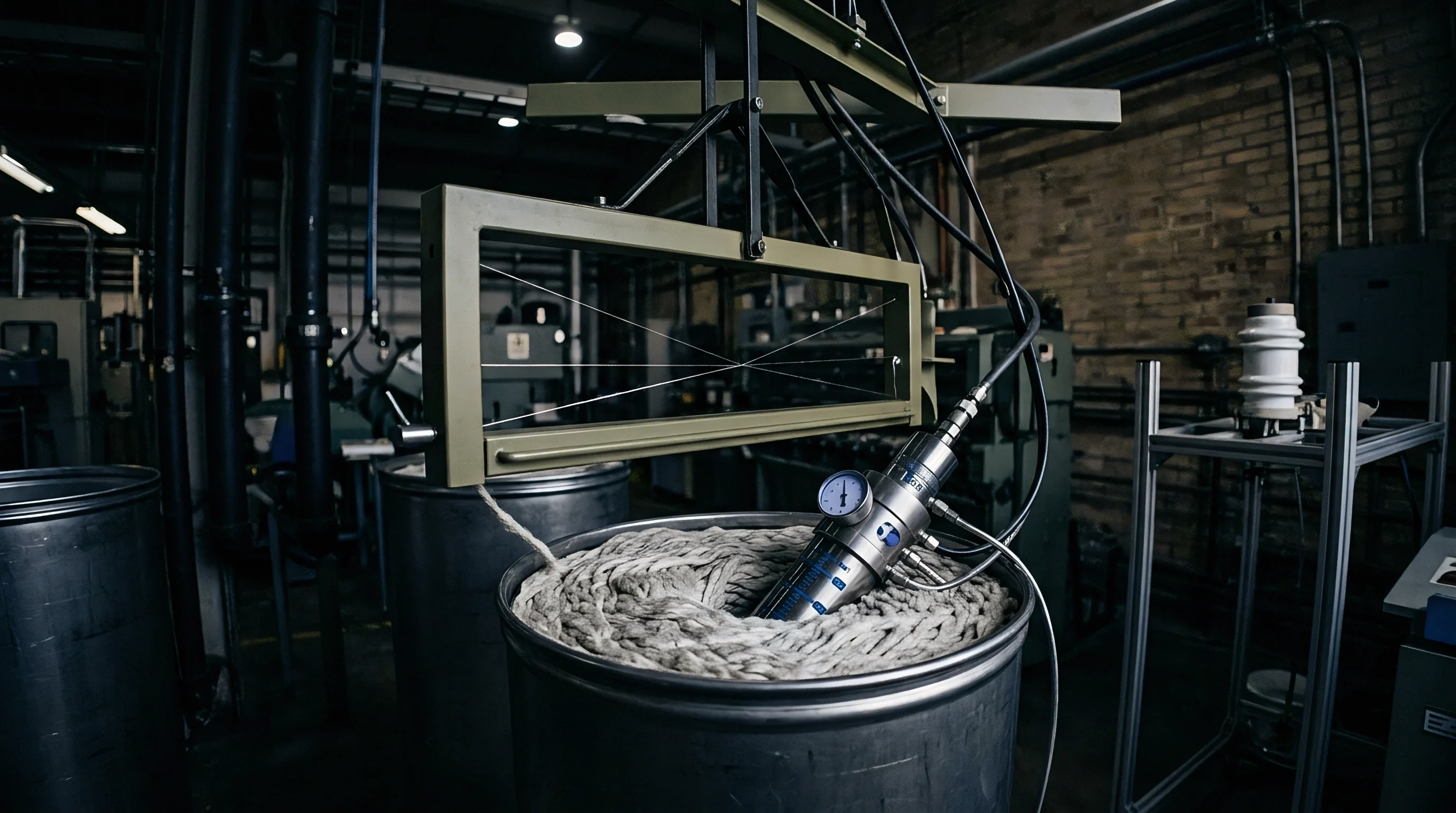
Inline oscillating sensors operate through electromagnetic excitation of a fluid-carrying geometry, typically an omega-shaped, straight, or bent balanced pipe loop. The fluid mass oscillating inside the geometry alters the natural structural period. As process liquid density rises with added dissolved alkali solids, the mechanical cycle lengthens in direct proportion to the added mass.
Modern installations mount the pickup loop downstream of dynamic chemical mixers immediately before the padder trough. The total volume held between the mixing block and the cloth entry point governs the control lag.
A thirty-litre pad trough running at seventy metres per minute turns its chemical volume over every two minutes.
Pipe mounting orientation dictates sensor reliability across continuous dyehouse runs. Entrained micro-bubbles and suspended particulate represent the primary interference sources for oscillating systems. In vertical upward pipe runs, ascending fluid velocities sweep gas bubbles past the measurement zone, preventing pockets from accumulating at the conduit apex.
Horizontal lines collect sediment along the lower tube radius and trap air along the upper crown, causing artificial density depressions that corrupt the dosing algorithm. Positioning the sensor inside a dedicated bypass loop with automated three-way isolation valves maintains continuous processing during cleaning cycles.
Cavitation destroys measurement integrity. When high-pressure pump strokes generate localized pressure drops below liquid vapour pressure, microscopic voids form and collapse against the inner conduit walls. Sizing the feed circuit to preserve a minimum backpressure of two bar across the sensing element keeps dissolved gases in continuous solution.
Pulsation dampeners installed immediately downstream of positive displacement diaphragm dosing pumps flatten hydraulic shocks that would otherwise trip the electromagnetic drive coils.
Fabric construction sets the required liquid liquor consumption rate. Heavy cotton twills demanding high pick-up require larger instantaneous chemical volumes than lightweight plain weaves. The sensing loop must maintain laminar to low-turbulent flow regimes regardless of cloth speed.
Excess turbulence introduces hydraulic noise that widens sensor output scatter, while stagnant boundaries prolong dead time.
Fluid acceleration inside curved measuring conduits creates secondary flow vortices that shear agglomerated dye particles. Stainless steel alloys conforming to AISI 316L resist diluted caustic media, yet concentrated sodium hydroxide at elevated temperatures promotes stress corrosion cracking along welded sensor joints. For baths combining hot alkali with aggressive saline electrolytes, titanium grade 2 or nickel-molybdenum alloys provide necessary galvanic resistance.
Equipment fabricators commonly attribute sudden zero-point baseline shifts to hydraulic pipe strain rather than acknowledge structural stress corrosion cracking along internal measuring tube welds.

Frequency
Oscillating period measurements translate directly into absolute specific gravity through fundamental harmonic equations. The resonant conduit behaves as a mass-spring system where mechanical stiffness remains fixed by metallurgical construction and wall thickness. Adding fluid mass increases the moving inertia, dropping the natural harmonic vibration rate.
Sensor drive coils pulse continuously at the circuit resonance point, while optical or magnetic pickups capture real-time period counts down to nanosecond precision.
The mathematical extraction links fluid mass per unit volume to the squared vibration period through factory-calibrated tube coefficients. Because temperature shifts alter the Young modulus of the metal tube as well as the thermal expansion volume of the dye liquor, an embedded four-wire platinum resistance detector sits against the outer conduit wall. Automated transmitters apply polynomial temperature normalization, converting dynamic readings to equivalent values referenced to twenty degrees Celsius.
| Caustic Soda NaOH (g/L) | Specific Gravity (g/cm³) | Degrees Baumé (°Bé) | Resonant Period Offset (μs) | Hydraulic Viscosity (mPa·s) |
|---|---|---|---|---|
| 35.0 | 1.038 | 5.3 | +142.1 | 1.18 |
| 50.0 | 1.054 | 7.4 | +201.8 | 1.29 |
| 75.0 | 1.081 | 10.8 | +303.4 | 1.52 |
| 100.0 | 1.108 | 14.1 | +405.0 | 1.83 |
| 125.0 | 1.135 | 17.2 | +507.2 | 2.24 |
Dissolved alkali solutions show steep density increases with small mass additions. A variation of two grams per litre of pure sodium hydroxide shifts solution density by approximately 0.0022 grams per cubic centimetre. This differential corresponds to roughly eight microseconds of sensor period shift on a standard twelve-millimetre measuring conduit.
Resonant instruments resolve density differences to 0.0001 grams per cubic centimetre, granting the control loop resolving resolution twenty times finer than the acceptable physical dyehouse tolerance band.
Thermal swings alter fluid expansion. Unjacketed delivery piping running through unconditioned finishing departments experiences twenty-degree diurnal temperature swings. Uncorrected, this environmental variance registers as an apparent density swing of 0.009 grams per cubic centimetre, sufficient to induce false pump throttling.
Dynamic temperature compensation algorithms running inside the transmitter recalculate fluid density at five hundred millisecond intervals, decoupling ambient environmental drifts from chemical addition rates.
A temperature shift of five degrees Celsius moves uncompensated alkali density readings by three kilograms per cubic metre.
Signal filtering dampens mechanical rumble from the continuous range drive. Squeeze roll motors, fabric beaters, and reciprocating folder arms transmit low-frequency physical vibrations through structural factory beams. High-precision sensor installations isolate the measuring spool with flexible PTFE braided expansion joints on the inlet and outlet ports.
Digital low-pass filters strip out mechanical plant frequencies below forty hertz while passing true fluid density transitions to the programmable logic controller.
How the controller distinguishes between alkali concentration spikes and background sodium sulfate variations remains an unresolved engineering compromise in multi-component pad liquors.

Feed
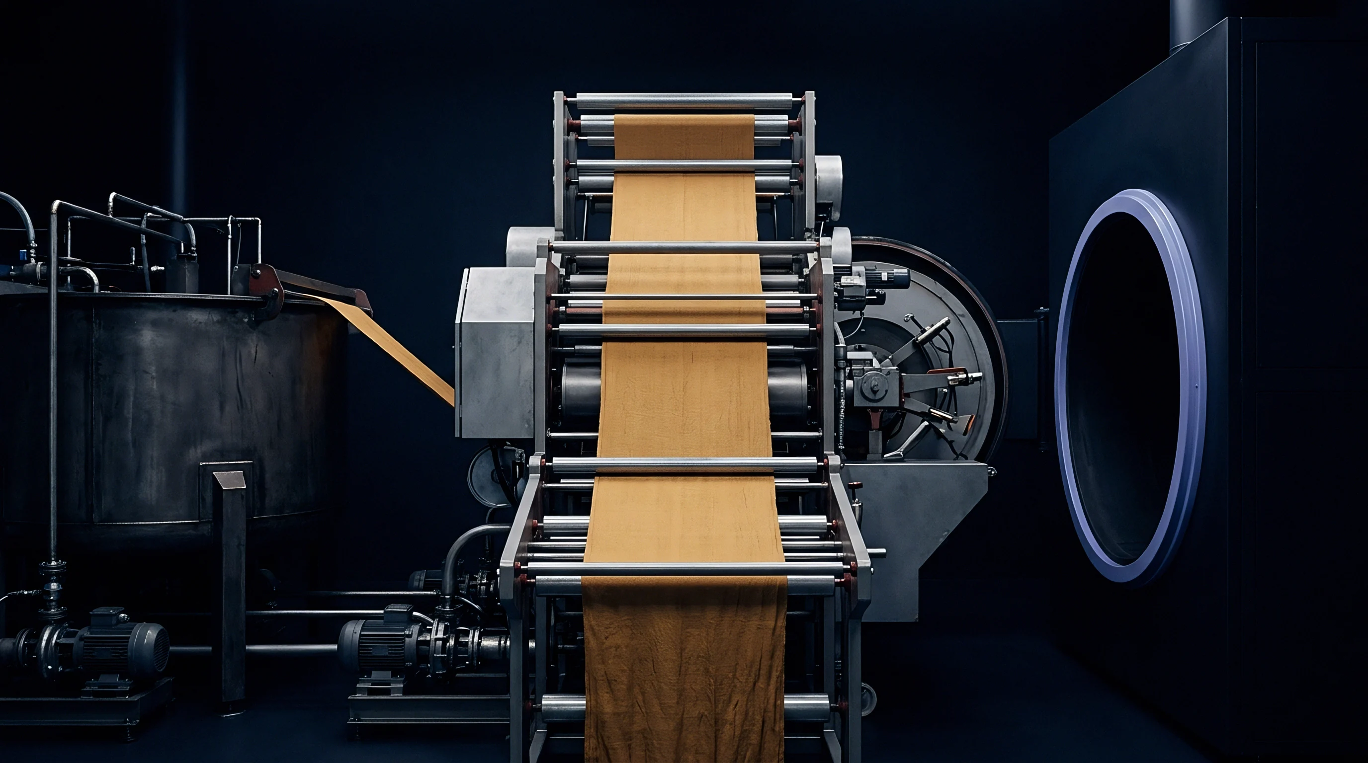
Proportioning systems govern the delivery of reactive colourants and activator solutions into compact pre-pad mixers. Cold pad-batch and continuous pad-steam operations separate concentrated dye solutions from caustic soda until seconds before trough immersion. Premature combination triggers rapid hydrolysis, converting expensive reactive dyestuff into unfixable waste that stains wash boxes and reduces colour fastness ratings.
Closed-loop alkali control adjusts secondary metering pump speed based on resonant feedback from the mixed delivery pipe.
The dosing sequence executes precise volumetric tracking against the linear speed of the fabric range. When the line ramps from twenty to eighty metres per minute during morning startup, chemical demand quadruples. Volumetric dye feed meters track range speed, while the resonant density sensor confirms that the accompanying alkali flow maintains the precise stoichiometric ratio required for the dye class.
The control loop continuously arbitrates between total mass flow and measured stream density.
- Flow verification registers baseline carrier liquor mass rate entering the dynamic mixing chamber.
- Alkali injection meters concentrated sodium hydroxide and water glass via progressive cavity dosing pumps.
- Resonant interrogation measures composite stream density down to four decimal places within two seconds of blending.
- PID compensation trims the frequency inverter driving the chemical stroke pump to correct measured density offsets.
- Alarm latching halts fabric feeding when density values drift beyond target limits for more than fifteen seconds.
Alkali dosing dictates chemical fixation. Reactive vinyl sulfone and triazine chemistries demand narrow pH bands between 10.8 and 12.2 depending on temperature and dwell time. Below this target, dye molecules fail to form covalent bonds with cellulose hydroxyl groups, resulting in weak depth and pale yardage.
Above this window, caustic soda accelerates hydrolysis, exhausting dyestuff in the bath and causing trailing tailing defects across thousand-metre production rolls. Maintaining density within a tolerance band of plus or minus 0.0008 grams per cubic centimetre stabilizes the fixation equilibrium.
Control loop tuning parameters must accommodate hydraulic residence time between chemical injection ports and the resonant measuring tube. If the proportional-integral-derivative algorithm attempts aggressive corrections without accounting for piping transport delay, severe chemical hunting occurs. Dosing valves cycle between full open and closed states, producing alternating light and dark bands across the running fabric.
Setting integral reset times equal to twice the fluid transport delay eliminates loop oscillation.
Tuning the chemical integration loop to match piping transit volume prevents continuous concentration hunting.
Automated flushing cycles safeguard the precision measuring tube during line stoppages. When the continuous range pauses for cloth seam stitching or batch changes, standing alkali and reactive dye begin cross-linking and gelling within stagnant pipe legs. Automated pneumatic bypass valves route warm water through the sensor loop within thirty seconds of line deceleration.
This automated sweep cleans the interior tube walls and establishes a pristine water density zero-point calibration check before the next dye run begins.
Match chemical delivery volume to padder expression capacity rather than tank size.

Viscosity
Rheological variance inside the dye bath perturbs simple harmonic resonance models. Industrial pad liquors contain more than pure alkali and water: they carry wetting agents, antimigrants, urea, dissolved dyestuffs, and sequestering auxiliaries. High-molecular-weight sodium alginates or polyacrylate antimigrants increase apparent fluid viscosity.
Heavy damping forces oppose conduit wall vibration, attenuating the oscillation amplitude and skewing raw frequency extraction toward artificially elevated density values.
Resonant tube geometries handle damping resistance through dual-frequency excitation or advanced amplitude monitoring. By tracking the mechanical power required to sustain oscillation at a stable target amplitude, the sensor transmitter calculates fluid viscosity simultaneously with fluid density. Dedicated firmware algorithms apply internal calibration curves that subtract viscous drag effects from the resonance period, restoring mass determination accuracy even in baths containing fifteen grams per litre of viscous migration inhibitors.
| Auxiliary Chemical Class | Concentration Range (g/L) | Dynamic Viscosity Shift (mPa·s) | Apparent Density Drift (g/cm³) | Compensation Correction Method |
|---|---|---|---|---|
| Sodium Alginate Antimigrant | 5.0 to 20.0 | +8.5 to +45.0 | +0.0042 to +0.0165 | Multi-parameter viscosity matrix subtraction |
| Polyacrylic Acid Thickener | 2.0 to 10.0 | +12.0 to +80.0 | +0.0068 to +0.0290 | Phase-shift damping angle tracking |
| Nonionic Wetting Agent | 1.0 to 4.0 | -0.1 to +0.3 | -0.0015 to -0.0035 | Aeration suppression via line backpressure |
| Sodium Sulfate Electrolyte | 20.0 to 80.0 | +0.2 to +0.8 | +0.0140 to +0.0580 | Baseline chemical salt offset subtraction |
| Urea Hydrotropic Agent | 10.0 to 50.0 | +0.1 to +0.5 | +0.0030 to +0.0150 | Recipe concentration matrix scaling |
Chemical fouling on inner sensor walls represents the most persistent operational failure mode in continuous pad dyeing. Sodium silicate used as an alkali buffer in pad-batch dyeing precipitates as insoluble glassy films along cold metal surfaces. This rigid coating adds dry structural mass to the tube while simultaneously stiffening the conduit spring rate.
The baseline resonance drifts upward, masquerading as an apparent rise in alkali strength and prompting the controller to starve the bath of real caustic soda.
Silicate glass coats sensor bores. The padder nip expresses excess solution. Entrained air drops the resonant reading.
Systematic maintenance demands automated chemical clean-in-place sequences running five percent acetic acid flushes followed by hot water rinses after every production shift.
- Tube scaling forms dense mineral laminates that shift mechanical tare weight upward.
- Cavitation pitting erodes inner conduit surfaces, lowering baseline tube mass permanently.
- Micro-bubble foaming dampens resonant amplitudes, driving density readings sharply negative.
- Auxiliary stratification produces uneven liquid boundaries inside measuring tubes during low-velocity runs.
Ignoring viscosity-induced damping corrections skews alkali delivery by up to twelve percent, causing severe shading across the width of continuous woven goods and triggering immediate lot rejection at the garment cutting floor.

Invoice
Commercial margins in contract continuous dyeing dissolve when chemistry controls fail. Continuous ranges process sixty to one hundred metres of woven goods every minute. A concentration drift that goes undetected across a four-hour production shift ruins twenty thousand linear metres of cloth.
When the finished goods reach the garment factory inspection frame, shade variations exceeding 0.8 dE CMC under standard illuminants trigger immediate quality dispute claims, chargebacks, and rejection of entire delivery batches.
Capital expenditure for an industrial-grade inline resonant density system typically totals twenty to thirty-five thousand US dollars, including sensor spools, titanium flow paths, automated bypass valves, and controller integration. Against this initial outlay stands the severe financial cost of shade reprocessing or cloth write-down. Stripping and re-dyeing off-shade reactive cotton fabrics costs roughly 0.45 dollars per linear metre in supplemental water, auxiliary chemistry, thermal gas consumption, and machine capacity loss.
A production run of thirty thousand metres suffering shade rejection consumes more re-dyeing capital than the installed cost of dual resonant density monitors.
Fabric construction sets the economic stakes of wet processing failures. Consider a high-density combed cotton twill woven with forty-single warp yarns and thirty-single weft yarns at twenty-eight picks per centimetre, finished at 240 grams per square metre for premium workwear. Greige cloth costs exceed 2.20 dollars per metre.
Sourcing houses cannot simply strip and re-dye sensitive technical workwear or high-visibility fabrics without compromising mechanical tear strengths and degrading abrasion resistance beneath required specification thresholds.
| Operational Control Mechanism | Off-Shade Scrap Risk (%) | Chemical Waste Vol / Month (L) | Unscheduled Downtime (Hours) | Net Financial Loss Risk (USD) |
|---|---|---|---|---|
| Manual Hydrometer Dip Cup Tracking | 4.2 | 12,500 | 38.0 | 46,200 |
| Periodic Laboratory Titration Checks | 2.8 | 7,200 | 22.0 | 30,800 |
| Conductivity Probe Immersion Loop | 1.9 | 4,100 | 15.0 | 20,900 |
| Inline Resonant Density Sensor Loop | 0.3 | 650 | 2.5 | 3,300 |
Conductivity electrodes frequently foul in dense silicate baths, blinding polarization surfaces within hours of startup. Resonant density sensors maintain non-contact mechanical measurement through sealed smooth-bore conduits, delivering operating lifetimes that routinely exceed eight years in corrosive chemical environments. The resulting data logs provide unalterable audit trails of chemical concentration throughout each continuous production run.
Every off-shade metre costs margin. Shade variance creates cutting waste. Density tracking catches chemical drift.
Mass meters record total mass flow. Hydrolysis wastes active dye molecules.
Purchase contracts stipulating compliance with ISO 105-J03 colorimetric tolerance limits shift financial liability for non-conforming roll yardage squarely onto wet processing mills when verified real-time process monitoring logs are missing from the delivery dossier.