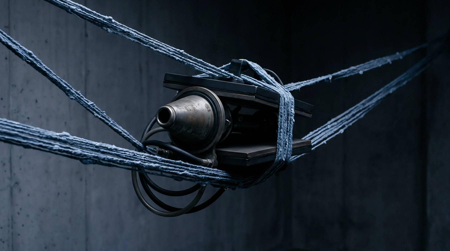
Valve Assembly
Regulation equipment deployed inside steam distribution networks within dye houses controls the header pressure delivered to cylindrical batch processing machines. Dynamic pressure balancing valve mechanisms operate by translating fluctuating inlet forces from central boiler headers into steady downstream delivery pressures inside closed fluid circuits. Water hammer events damage delicate interior heat exchangers if line velocities spike without immediate mechanical intervention.
Diaphragm assemblies react proportionally against calibrated spring loads to throttle fluid flow instantaneously during sudden demand shifts across the dye house floor. Maintenance crews inspect these internal diaphragms annually to prevent seal degradation that causes steam leakage and pressure drift. Operating parameters drop outside acceptable tolerances when supply headers experience severe pressure drops exceeding design limits.
Factory acceptance testing protocols verify that each unit maintains output stability within strict thresholds before installation on production lines.
Hydraulic Response
Internal piston movements counteract sudden upstream pressure spikes by adjusting orifice sizes through mechanical feedback loops inside the valve body. Fluid entering the high pressure chamber acts upon the lower face of the sensing piston to compress opposing calibration springs. Dynamic pressure balancing valve units rely on this direct mechanical antagonism to absorb hydraulic shock without relying on external pneumatic controllers.
Orifice restriction coefficients shift continuously as the main plug travels along its vertical axis during operational cycles. Valve hysteresis remains low because polished bronze bushings minimize sliding friction during rapid positional adjustments. Production supervisors monitor these response times closely because sluggish mechanical action permits damaging pressure surges to reach sensitive heat exchangers.
Load Distribution
Steam headers feeding multiple scouring ranges require synchronized pressure control to prevent starving downstream equipment during peak operational periods. Multiple branch lines drawing from a single trunk demand proportional flow allocation to maintain uniform temperature profiles across all connected vessels. Dynamic pressure balancing valve devices distribute thermal energy evenly by throttling secondary circuits whenever primary header pressures decline unexpectedly.
Mill engineers calculate required flow coefficients based on maximum anticipated steam consumption figures across all connected machinery groups. Thermal efficiency improves measurably across the entire wet processing department once balanced headers eliminate localized starvation events.
Verification Check
Quality control technicians measure operational performance on dedicated test benches before approving units for mill installation. Technicians record actual downstream pressures against known input fluctuations to confirm compliance with manufacturing specifications. Dynamic pressure balancing valve components pass final inspection only when output variance stays beneath designated manufacturing limits during simulated plant conditions.
Calibration records accompany every approved shipment to provide traceability for plant safety auditors. Field adjustments require specialized torque wrenches to prevent over tightening the spring housing during routine maintenance procedures. Factory inspectors reject any assembly showing excessive stem play during cyclical pressure testing routines.