Determining Venturi Nozzle Insert Sizing for Jet Dyeing Light Woven Fabrics
Determine light woven jet nozzle sizing by matching compressed rope cross-section plus forty percent liquor annulus area to prevent abrasion and creases.
Orifice
Venturi nozzle selection governs hydraulic shear, fabric velocity, and internal machine pressurization inside high-temperature jet dyeing vessels. Light woven constructions ranging from 45 to 110 grams per square metre require deliberate constriction control to maintain continuous liquor-to-goods displacement without shredding low-denier yarns. Standard tubular nozzle inserts range from 50 to 140 millimetres in internal diameter.
Specifying an oversized throat diameter induces mechanical slippage across the lifter reel, resulting in structural plucking, loop stagnation, and persistent rope abrasion against chamber guide walls.
An undersized orifice introduces excessive fluid acceleration across the convergence cone. The resulting hydrodynamic drag pulls warp and weft filaments past their yield points, generating irreversible crease marks, edge curling, and yarn displacement. Selecting the correct cross-sectional aperture demands balancing the total bulk volume of the collapsed rope against pump flow rates and lifter reel circumferential surface speeds.
Light wovens collapse into tight, dense ropes under mechanical tension. Unlike circular knits that expand into open cushions, lightweight polyester voiles, nylon ripstops, and fine silk habotai channel fluid exclusively along their exterior perimeters inside the nozzle body. The internal throat clearance must balance liquor bypass velocity with mechanical clearance margins to prevent high-pressure fluid cavitation.
Nozzle throat velocity for delicate filament wovens caps out between 250 and 320 metres per minute to prevent structural filament rupture.
Rope cross-sectional area derives from fabric aerial mass, nominal finished open width, and the specific bulk density factor of the polymer substrate. The target throat diameter provides sufficient cross-sectional area for the compressed rope while reserving thirty to forty-five percent of the internal orifice area for liquor flow. Insufficient liquor annulus area starves the fabric rope of hydrodynamic lubrication, producing intense friction against the stainless steel insert walls.
Operating a nozzle beyond its geometric clearance threshold causes rope jamming, automated pump trip halts, and permanent dye unlevelness from localized thermal shock. When an engineering team pairs an incorrect throat insert with high-twist wovens, the resulting mechanical pinch creates permanent longitudinal crush fractures that survive tentering, heat setting, and final sanforization passes.

Choke
Hydrodynamic convergence profiles define how pump discharge pressure transforms into kinetic fluid acceleration inside the transport chamber. Standard jet machines feature either symmetrical conical inserts or stepped venturi profiles. Conical profiles deliver steady hydrostatic compression.
Stepped venturi nozzles incorporate an abrupt restriction ring followed by an elongated diffuser horn, amplifying the forward kinetic impulse per unit volume of circulated bath.
Fabric transport velocity links directly to pump impeller frequency and system backpressure. Light woven constructions exhibit minimal longitudinal elasticity. When the liquor jet travels significantly faster than the lifter reel drives the cloth, the resulting velocity differential generates acute longitudinal strain.
This elongation destroys delicate filament cover factors, opening visible light gaps along warp seams.
Can Divergent Throat Geometries Suppress Running Creases?
Longitudinal running marks occur when a woven rope maintains an identical fold geometry across multiple circulation cycles inside the transport tube. The divergent diffuser section located downstream of the minimum throat aperture controls rope ballooning. Expanding the cross-sectional area along a six-degree tapered cone induces a controlled pressure recovery drop, forcing trapped liquor outward through the fabric folds.
This pressure differential balloons the lightweight woven tube immediately upon exiting the nozzle throat. The sudden volumetric inflation redistributes rope creases, ensuring that no single warp thread line sustains continuous internal bend stress across successive turns. Insufficient divergence angles fail to trigger hydrodynamic opening, locking the rope into fixed creases throughout high-temperature exhaustion cycles.
| Substrate Construction | Areal Weight Range | Recommended Nozzle Inner Diameter | Nozzle Liquor Flow Target | Fabric Speed Parameter | Operating Pressure Differential |
|---|---|---|---|---|---|
| Polyester Micro-Taffeta (50D/72F) | 50 to 65 g/m² | 65 mm | 45 to 55 m³/h | 280 to 320 m/min | 0.35 to 0.45 bar |
| Nylon 6,6 Ripstop (20D/24F) | 35 to 48 g/m² | 55 mm | 35 to 45 m³/h | 240 to 280 m/min | 0.25 to 0.35 bar |
| Viscose Plain Chiffon (75D) | 60 to 80 g/m² | 75 mm | 50 to 60 m³/h | 200 to 240 m/min | 0.20 to 0.30 bar |
| Silk Crepe de Chine (14 mm) | 55 to 70 g/m² | 70 mm | 40 to 50 m³/h | 180 to 220 m/min | 0.15 to 0.25 bar |
| Cotton Poplin Greige (80s/1) | 85 to 110 g/m² | 90 mm | 60 to 75 m³/h | 260 to 300 m/min | 0.40 to 0.55 bar |
Operating pressures across the nozzle body scale with liquor velocity squared. Exceeding recommended backpressures shifts laminar boundary layers into turbulent vortex shedding, which distorts low-twist fill yarns in sheer wovens. Mill technicians often claim that increasing pump pressure guarantees level dyeing on sheer articles, overlooking how mechanical shear disrupts weave balance.

Draft
Synchronization between the overhead motorized lifter reel and the fluid venturi jet establishes mechanical tension through the process path. In light woven dyeing, tension must approach neutral equilibrium. The lifter reel lifts the wet rope from the vessel floor trough, whereas the fluid nozzle accelerates it through the transport tube into the rear plaiter collector.
Lead ratios define the percentage difference between lifter reel tangential speed and calculated liquor transport velocity. A reel running faster than the nozzle exerts aggressive upward pulling force on fragile wet warps. A reel lagging behind the nozzle causes fabric accumulation at the convergence throat, triggering safety interlocks or inducing severe entanglement inside the jet chamber.
- Positive overfeed calibration prevents tensile thinning on high-tenacity filament webs by ensuring the lifter reel delivers fabric directly into the liquor stream at matching linear velocities.
- Chamber liquor ratio control maintains hydraulic buoyancy inside the cloth trough, reducing gravitational drag forces as the wet rope ascends toward the overhead reel.
- Torque-controlled motor drives dynamically reduce mechanical pull when bath viscosities climb during intermediate cooling and rinsing wash sequences.
- Trough lubrication chemistry minimizes inter-yarn sliding friction, allowing lightweight high-sett weaves to pass through mechanical transitions without surface chafing.
Fabric elongation properties directly dictate permissible lead speed tolerances. Low-elasticity filament weaves tolerate less than three percent speed variance before showing signs of thread distortion. In contrast, texturized micro-filament fabrics tolerate wider margins due to internal yarn crimp elasticity that absorbs transient hydrodynamic shocks.
Operating without verified synchronization between drive reel surface speed and fluid discharge velocity voids manufacturer claims for tensile yarn retention.
Circulation cycle frequency governs overall shade levelness on light woven ropes. A typical cycle time of fifty to sixty seconds per loop ensures uniform dye exhaustion without over-stressing delicate surfaces. Extending cycle durations past seventy seconds raises shade variance across the rope, while speeding below forty-five seconds subjects fragile structures to excessive abrasion cycles per liquor turnover.
A supplier who blames poor batch quality on raw greige filament inconsistency often hides incorrect drive synchronization parameters on the machine floor.

Scuff
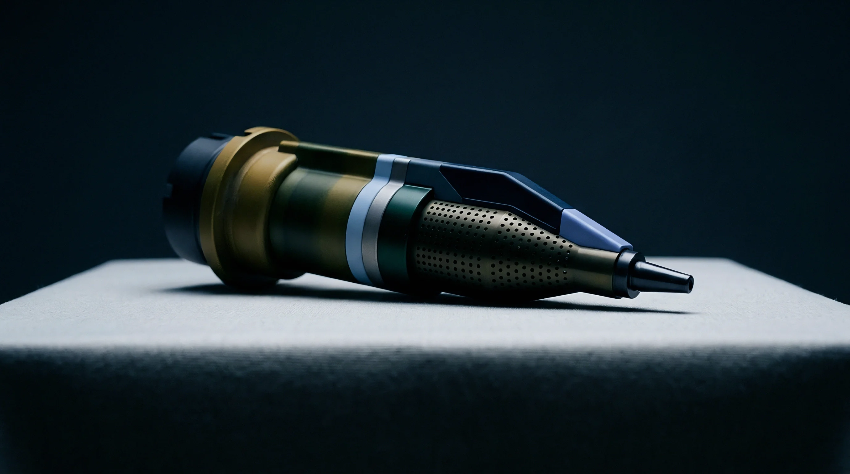
Mechanical abrasion manifests rapidly when high-velocity liquor streams force delicate light wovens against stationary metal walls. Micro-abrasion appears as localized frosting, edge whitening, yarn slippage, or localized pilling on fine filament faces. When the venturi orifice internal diameter is miscalculated, the balance of hydrostatic centering forces dissolves.
Hydraulic self-centering represents the primary protective mechanism inside an active venturi throat. Symmetrical annular fluid injection creates an uninterrupted fluid cushion around the traveling rope core. If nozzle diameter is specified too large, the fluid film breaks apart into irregular channel streams.
The fabric rope drops from suspension and drags across bare stainless steel walls.
Will Internal Friction Destroy Low Filament Counts?
Filament denier per filament metrics determine substrate vulnerability to shear-induced fibrillation. Microfibers under 1.0 denier per filament possess high surface area ratios that readily snag on surface roughness within cast nozzle components. Mechanical polishing specifications for internal nozzle inserts demand mirror-smooth electro-polishing down to Ra values below 0.2 micrometres.
Coarse surface finishes act as abrasive files against high-speed fabric ropes. Even minor tooling scores or localized scale pitting inside the convergent cone strip outer filament jackets, leading to permanent line marks down the goods. The following sequential diagnostic procedure identifies mechanical abrasion origins across wet-processing channels:
- Stop machine circulation immediately upon noticing visual surface disturbance during intermediate sampling extraction steps.
- Inspect the entry lip of the venturi cone for polymer deposit buildup, scouring oil residues, or localized burrs using a high-resolution bore inspection tool.
- Measure mechanical clearance between the external diameter of the running rope and the narrowest internal restriction band using calibrated plug gauge sets.
- Verify delivery pressure margins at the pump discharge manifold against the original equipment operating curves to ensure uninterrupted annular fluid film maintenance.
- Evaluate rinse cycle chemistry to confirm adequate boundary-layer lubricating agents remain active until complete bath drop discharges.
Correct insert sizing isolates the moving substrate within high-velocity fluid walls, preserving structural surface integrity. When mechanical tolerances degrade through neglected maintenance, the resulting surface haze remains entirely uncorrectable during downstream chemical softening stages.
Contractual agreements specifying four-point inspection standards strictly penalize persistent longitudinal chafe marks, directly impacting invoice recoveries.

Metric
Calculating the correct nozzle throat diameter requires systematic empirical formulas rather than floor guesswork. The core calculation determines rope volume per linear metre, factors in wet volumetric swelling ratios, and provisions hydrodynamic liquor annulus space. The fundamental equation for required nozzle cross-sectional area balances fabric volumetric throughput and protective fluid bypass requirements.
Let fabric areal weight be W in grams per square metre, finished open width be B in metres, and substrate specific packing density be denoted by density constant rho in grams per cubic centimetre. The dry cross-sectional area of the consolidated fabric rope resolves into compact square millimetres before applying bath hydro-swelling multipliers.
Natural and synthetic fibers swell distinctly upon water immersion and surfactant contact. Cellulosic fibers absorb water and expand significantly, increasing compressed rope volume by twenty to thirty-five percent. Synthetic polyester and polyamide filaments maintain stable diameters, displaying volume expansions under eight percent governed primarily by surface water retention between filaments.
| Fiber Polymer Type | Bulk Packing Density | Wet Hydro-Swelling Factor | Target Annulus Area Ratio | Calculated Area Multiplier |
|---|---|---|---|---|
| Polyester (PET Fully Drawn) | 1.38 g/cm³ | 1.05 | 0.45 | 1.91 |
| Nylon 6 (Polyamide) | 1.14 g/cm³ | 1.12 | 0.40 | 1.87 |
| Viscose Rayon (Regenerated) | 1.50 g/cm³ | 1.35 | 0.35 | 2.08 |
| Mulberry Silk (Degummed) | 1.30 g/cm³ | 1.15 | 0.42 | 1.98 |
| Combed Cotton (Mercerized) | 1.54 g/cm³ | 1.25 | 0.38 | 2.02 |
| Values reflect standard wet-processing baths containing 1.5 g/L nonionic wetting auxiliaries at 60 degrees Celsius. |
Take an operational example processing a lightweight polyester micro-taffeta. The greige construction specifies an areal mass of 55 grams per square metre across an open width of 1.50 metres. Fabric throughput proceeds at a linear line speed of 300 metres per minute inside a high-temperature short-liquor vessel running at a 1:5 bath ratio.
The linear mass equals 82.5 grams per running metre. Given a polyester substrate packing density of 1.38 grams per cubic centimetre, the dry structural rope area occupies approximately 59.8 square millimetres. Incorporating the wet swelling multiplier of 1.05 expands the operating rope cross section to 62.8 square millimetres.
Hydrodynamic protection requires an annulus area fraction of 0.45, dictating that the fabric rope occupies fifty-five percent of the total throat aperture. Dividing 62.8 by 0.55 yields a total minimum nozzle throat area of 114.2 square millimetres under pure static compression models. Industrial reality mandates accommodating loose rope folding waves, requiring an empirical spatial dispersion factor of roughly twenty-five for lightweight woven drape geometries.
Applying the spatial dispersion multiplier yields a practical working cross-sectional area of 2,855 square millimetres. Resolving this area into internal circular diameter determines an optimal insert bore of 60.3 millimetres. The plant engineer selects a standardized 60-millimetre internal diameter venturi insert.
Selecting an oversized 80-millimetre insert drops fluid velocity below self-centering thresholds, forcing manual operator interventions. An undersized 50-millimetre insert creates excessive fluid friction, producing warp yarn distortions across entire dye lots.
The relationship between nozzle diameter and fabric weight leaves unresolved whether progressive weight reductions down to fifteen grams per square metre follow continuous hydrodynamic models or introduce discrete boundary effects.

Ledger
Capital commitments for premium wet-processing equipment depend heavily on tooling discipline within the dyehouse. Standard jet dyeing machinery ships with standard insert packages optimized for medium-weight knits. Processing technical light wovens requires precision-machined, electro-polished stainless steel or ceramic inserts tailored to specific aerial weight classes.
Specialized venturi inserts cost between four hundred and twelve hundred dollars per unit depending on alloy grades and internal polishing treatments. A four-port industrial machine requires four matched inserts per chamber configuration. Attempting to bypass tooling purchases by running light wovens through installed 110-millimetre knit inserts causes continuous yardage rejection, eroding production margins.
Material rejection on sheer wovens escalates conversion losses rapidly. A single five-hundred-kilogram lot of high-density micro-taffeta represents approximately 6,000 running metres of finished goods. Surface abrasions, rope creasing, and edge fraying relegate entire lots to second-quality off-price liquidation, instantly erasing profit margins across the processing schedule.
Production scheduling must absorb physical changeover durations between lots. Swapping nozzle inserts on modern jet vessels consumes forty-five to seventy-five minutes per machine. This downtime includes vessel draining, safety lockout sequences, mechanical flange unbolting, insert replacement, and leak pressure testing.
Rushing mechanical setup steps introduces serious alignment defects. An improperly seated insert flange introduces sharp mechanical steps within the fluid path, shredding woven goods at processing speeds. Dyehouse managers routinely balance the labor cost of changeovers against the risk of processing out-of-spec goods on installed tooling.
Procurement teams structuring request-for-quotation tenders must incorporate explicit tooling validation clauses. Specifications must mandate exact nozzle diameters, certified internal surface finishes, and verified fabric rope speed limits for every light woven quality. Leaving insert selection to unmonitored floor discretion guarantees elevated reject rates and missed shipment dates across international supply chains.
Standard purchase contract terms governing woven wet processing allocate all second-quality reclamation costs to the dyeing facility whenever lot inspection records confirm mechanical rope damage from incorrect machine tooling configurations.