Determining Loom Reed Denting Plans for High-Density Woven Fabrics
Determining loom reed denting plans for high-density weaves requires balancing target ends per centimetre against open air space ratio to prevent beat-up binding.
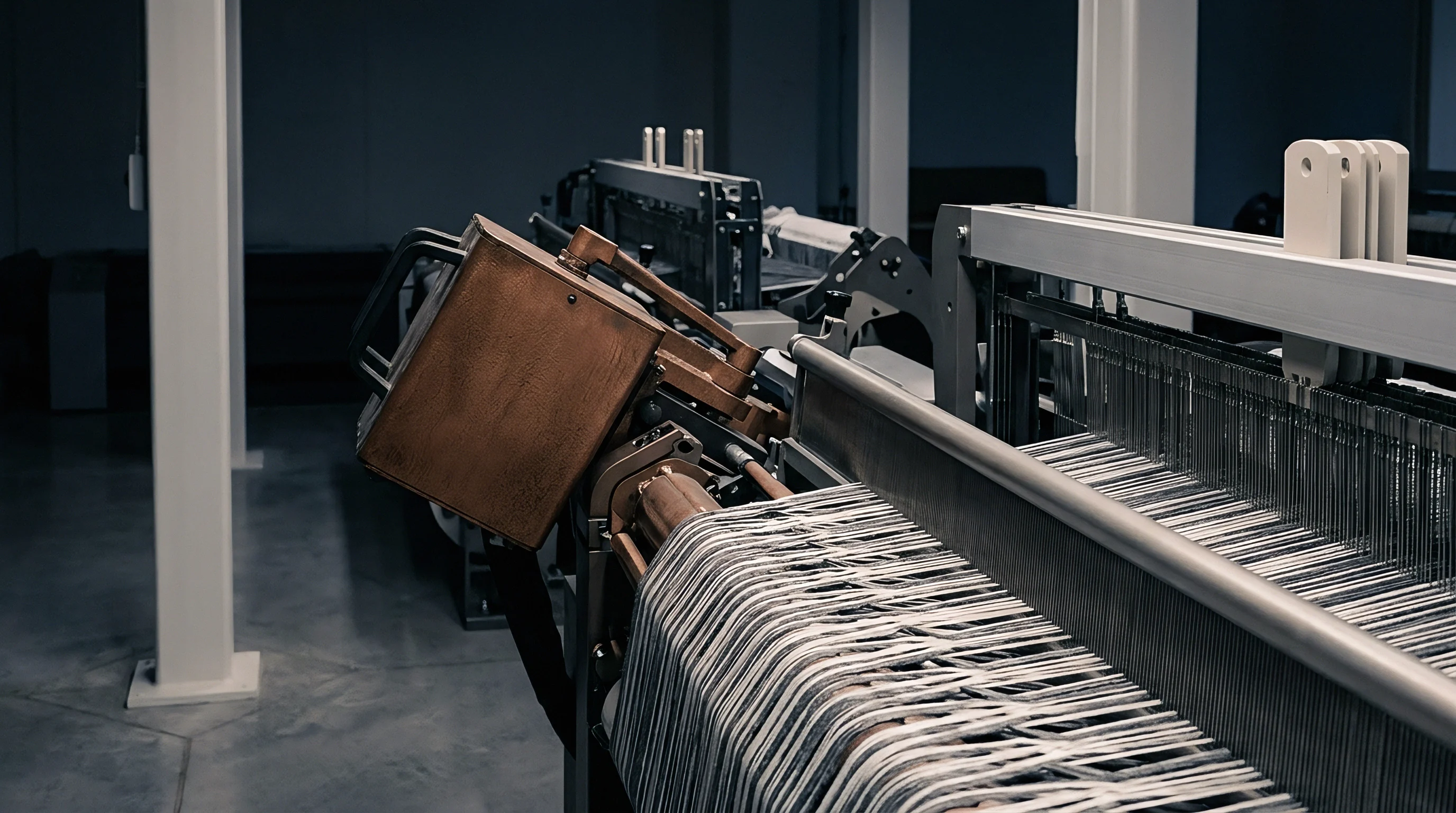
Dent
High-density woven fabrics, such as down-proof micro-filament taffetas, high-tenacity barrier materials, and ultra-dense cotton poplins, operate near the geometric limit of thread packing. Engineering a reed plan for these constructions requires establishing a precise distribution of total warp ends across the open channels of the loom reed. The calculation hinges on target finished warp density, reed width, off-loom shrinkage, and the physical wire dimensions of the comb.
Dividing the target warp ends per unit width by the chosen reed number determines the theoretical number of threads passing through each open space. High end counts increase beat-up friction. Achieving a finished warp density of seventy ends per centimetre on a fine-denier polyester fabric requires balancing the open space against yarn bundle compression to ensure the reed comb drives each pick firmly into the cloth fell without abrading the filament strands.
When warp density exceeds sixty percent of maximum theoretical packing according to square-jammed geometry, passing too many threads through a single channel creates excessive yarn-on-yarn friction during shed opening. Selecting a plan of two, three, four, or five threads per open split alters the mechanical forces acting at the fell line. Higher counts per split allow the weave shed to use a lower reed number with thicker, more rigid wires.
Concentrating excessive yarn bulk inside a single split restricts thread mobility, forcing adjacent ends to stack vertically during beat-up rather than spreading horizontally across the pick.
Ends per Space Selection Criteria
Determining the ideal grouping of thread bundles depends directly on linear yarn density, filament count, and yarn twist. Fine synthetic continuous filaments below thirty dtex perform predictably in three-end or four-end arrangements because their smooth cross-sections compress without severe filament migration. Spun yarns, particularly high-twist combed cottons, demand lower grouping densities, typically two ends per split, to prevent hairiness and neps from catching during shed movement.
Warp ends crowd inside individual gaps. When thread counts per split exceed four in spun constructions, adjacent threads cling together through mechanical entanglement. This entanglement delays shed separation, creating false warp stops and yarn floats.
In high-speed air-jet weaving operating above eight hundred picks per minute, delayed shedding produces mispicks and selvage tears. The selection strategy evaluates the tradeoff between structural comb rigidity and individual yarn clearance.
A reed occupancy exceeding sixty-five percent of open air space elevates warp yarn friction beyond three hundred grams of tension during beat-up on high-speed air-jet looms.

Air Space Ratio and Warp Cramming
The open area ratio defines the percentage of total reed width available for yarn passage, calculated from wire thickness and reed pitch. Standard stainless steel reed wires range from 0.20 millimetres to 0.50 millimetres in thickness. Thicker wires reduce the open channel.
A reed with a high count per centimetre constructed with thick wires restricts open air space below forty-five percent, causing severe warp cramming.
Cramming increases the normal force exerted by the wire faces against the moving yarn during beat-up. This sliding friction strips sizing agent off the warp ends, generating abrasive dust that clogs the reed channel and causes end breaks. For high-density fabrics, maintaining an open air space ratio between fifty and fifty-eight percent guarantees adequate clearance for knots and slubs while preserving structural rigidity under beat-up pressure.
- Shedding Obstruction occurs when thread packing exceeds sixty percent of open channel width, leading to clinging warp yarns and mispicks across the fabric body.
- Size Stripping develops under excessive wire contact pressure, generating fine particulate debris that deposits in the reed channel and accelerates thread abrasion.
- Filament Flattening appears on fine continuous synthetic yarns when overcrowding forces filaments into oval cross-sections, distorting light reflection along the warp axis.
- Splay Edge Separation results from aggressive denting changes near the selvages, creating localized tension spikes that snap outer threads during temples engagement.
Miscalculating the thread allocation across open split channels causes immediate mill losses through repeated warp breakages, abrasive size breakdown, permanent longitudinal shading lines, and catastrophic beat-up failure where the reed forces the cloth fell backward without advancing the weave.
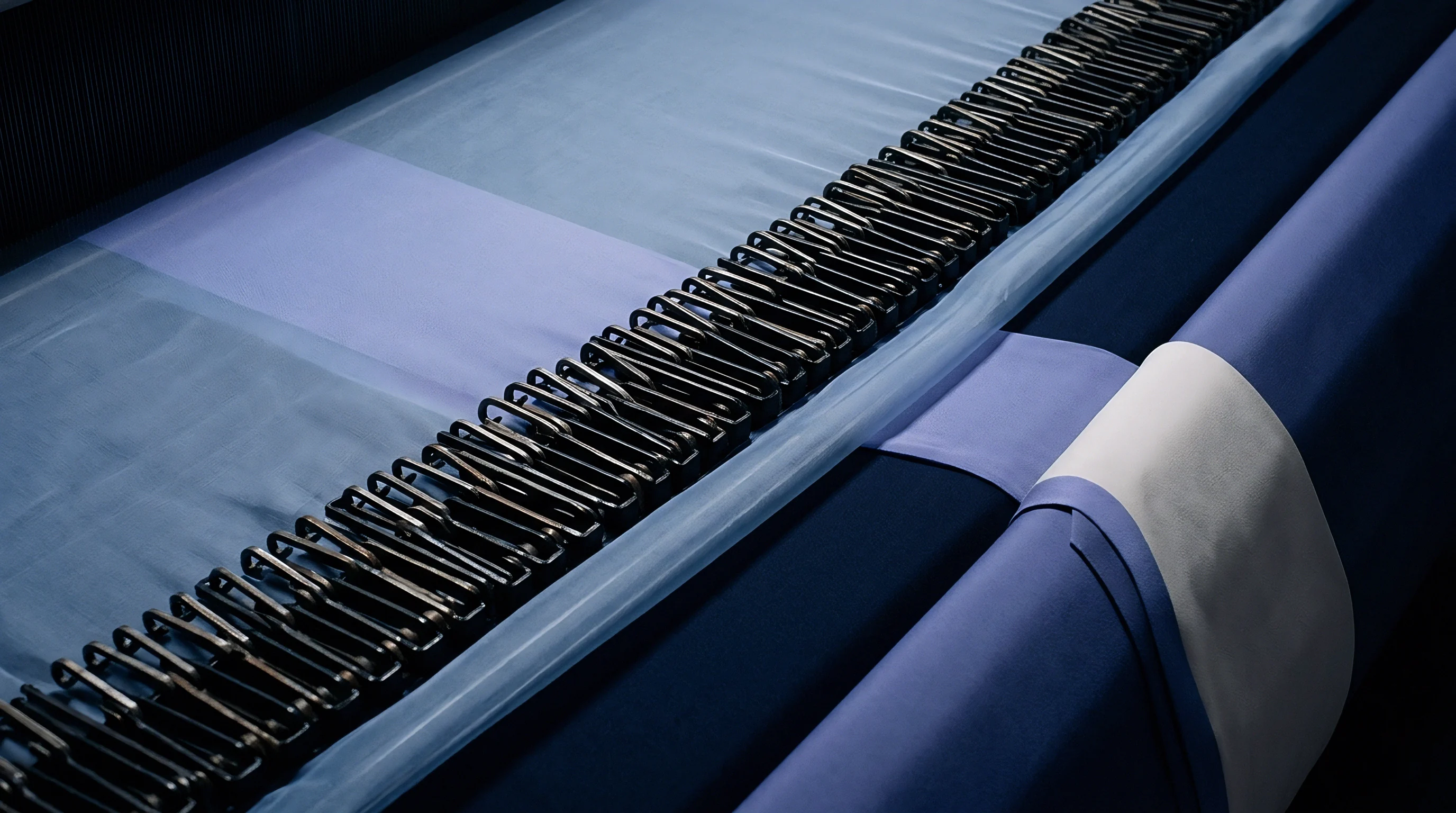

Pitch
Spacing between consecutive stainless steel dent wires governs the physical width of every open channel across the loom comb. In fine-count weaving reeds, pitch accuracy must be held within a tolerance of plus or minus two micrometres. Deviations in wire spacing alter the localized warp density, creating permanent physical variations in the woven sheet.
The lateral stability of the dent wire under high beat-up loads determines whether wire spacing remains uniform across the full reed length during continuous operation.
Beat-up forces on high-density barrier fabrics frequently exceed twelve hundred Newtons per metre of cloth width. Under these extreme loads, thin dent wires flex laterally. Wire deflection allows individual split channels to open slightly at the impact line, allowing thread bundles to shift out of alignment.
Standard spring-bound reeds lack the structural stiffness required for heavy beat-up; high-density weaves mandate hard-soldered or resin-bonded reeds with reinforced top and bottom ribs to suppress wire deflection.

Reed Wire Thickness and Deflection Limits
Selecting wire depth and wire thickness requires balancing structural resistance against channel clearance. Increasing wire depth from twenty-two millimetres to twenty-six millimetres increases lateral flexibility unless wire thickness increases proportionally. Flat oval wire profiles offer higher moments of inertia along the warp direction while preserving side-to-side channel width.
Flat wires maintain pitch accuracy. The mechanical deflections under peak beat-up impact can be evaluated across common high-density reed specifications using standard stainless steel alloy properties.
| Reed Number (Dents/10cm) | Wire Thickness (mm) | Air Space Ratio (%) | Maximum Recommended Warp Density (ends/cm) |
|---|---|---|---|
| 120 | 0.35 | 58.0 | 48.0 |
| 140 | 0.30 | 58.0 | 56.0 |
| 160 | 0.28 | 55.2 | 64.0 |
| 180 | 0.24 | 56.8 | 72.0 |
| 200 | 0.22 | 56.0 | 80.0 |

High Density Weave Shedding Clearances
Vertical shed opening demands sufficient clearance above and below the neutral warp line to allow unhindered shuttleless filling insertion. As the harness frames move to form the upper and lower sheds, warp ends travel vertically along the face of the dent wires. If wire surfaces exhibit micro-burrs or rough polishing marks from manufacture, vertical friction increases dramatically, leading to broken filaments and fuzz balls.
High-density filament constructions require air-jet reeds with plasma-polished or chromium-plated dent wire surfaces. Surface roughness values must not exceed Ra 0.05 micrometres. Smoother wire surfaces lower dynamic friction, allowing yarn bundles to glide vertically during shedding without creating static electricity or heat buildup at high loom operating speeds.
When DIN 60900 tolerances on reed wire pitch are exceeded, lateral warp clustering induces visual striping that invalidates grey cloth quality acceptance under ISO 13934 testing.
Selecting thicker dent wires with high flexural rigidity prevents wire bow during peak beat-up load and ensures long-term pitch stability across millions of loom insertion cycles.
Marking
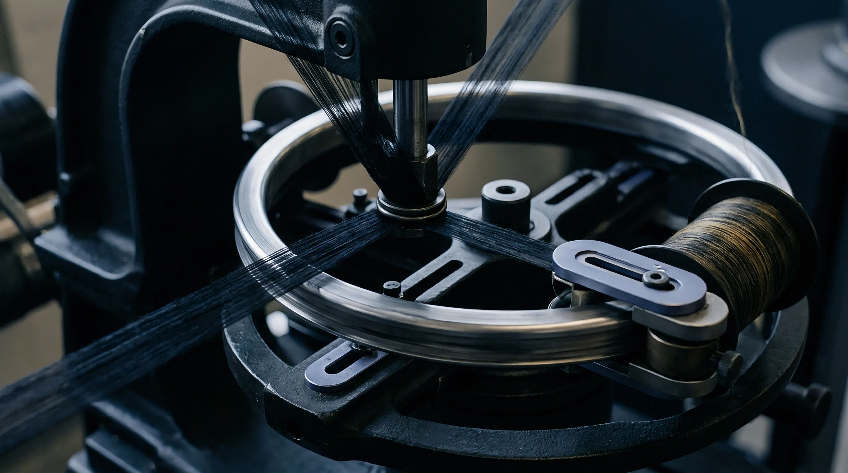
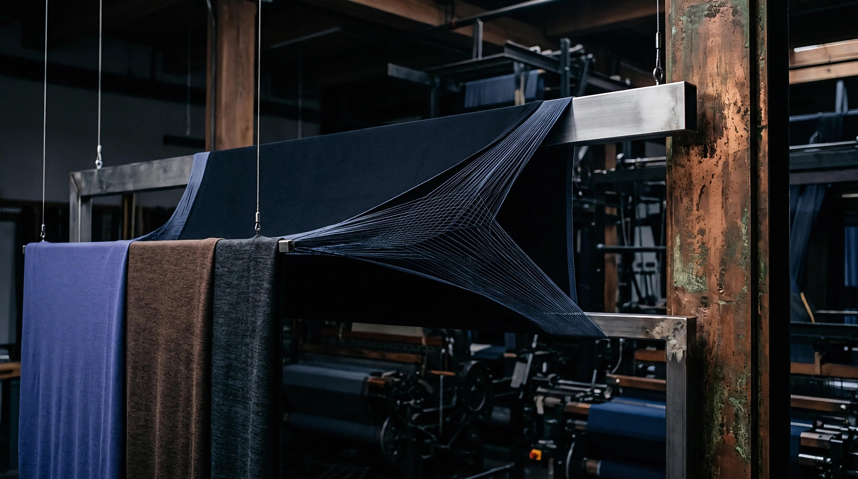
Optical uniformity in dense flat fabrics depends entirely on minimizing reed marks, which appear as micro-voids or low-density longitudinal bands between adjacent thread groups. When multiple warp ends pass through a single split, the dent wire physically separates one group of ends from the next group. Upon exiting the reed splits at the beat-up point, individual ends must migrate laterally to fill the empty space left by the wire thickness.
If fabric structural cover is high and filling yarn tension is elevated, threads are locked into position before they can spread uniformly. The gap left by the dent wire remains visible as a faint, repeating streak down the length of the cloth. Reducing ends per split from four to two cuts the thread bundle volume in half, accelerating lateral yarn migration at the fell line and smoothing out density variations.
Structural Streaks and Denting Uniformity
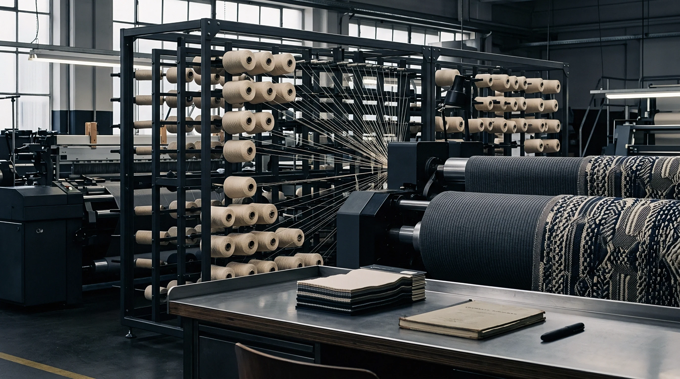
Eliminating longitudinal optical streaks requires matching the denting pattern to the weave structure repeating unit. In a four-harness 2/2 twill weave, choosing a three-end or five-end denting plan creates a structural mismatch between shedding sequence and split grouping. This mismatch shifts the wire position relative to the weave float, causing cyclic density waves that appear as prominent diagonal or vertical bands on finished cloth.
Aligning ends per split as an exact multiple or factor of the weave repeat ensures identical thread tension across every channel. For a four-harness construction, a two-end or four-end plan ensures that shedding splits warp ends symmetrically. Symmetric shedding balances beating pressure across all threads, encouraging rapid lateral spread upon fell contact.
- Weave Repeat Factor dictates selecting an ends-per-split value that divides evenly into the harness repeat to prevent cyclic structural band marks.
- Off-Loom Contraction Percentage determines the target reed width expansion necessary to force lateral thread spread into split clearance voids.
- Finishing Shrinkage Capacity calculates wet thermal relaxation energy required to shift locked filaments into empty spaces during scouring and drying.
- Beat-Up Back-Rest Oscillations establishes dynamic warp sheet relaxation timing to ease tension spikes at the exact moment of reed contact.
Where Do Warp Grouping Lines Soften during Finishing?
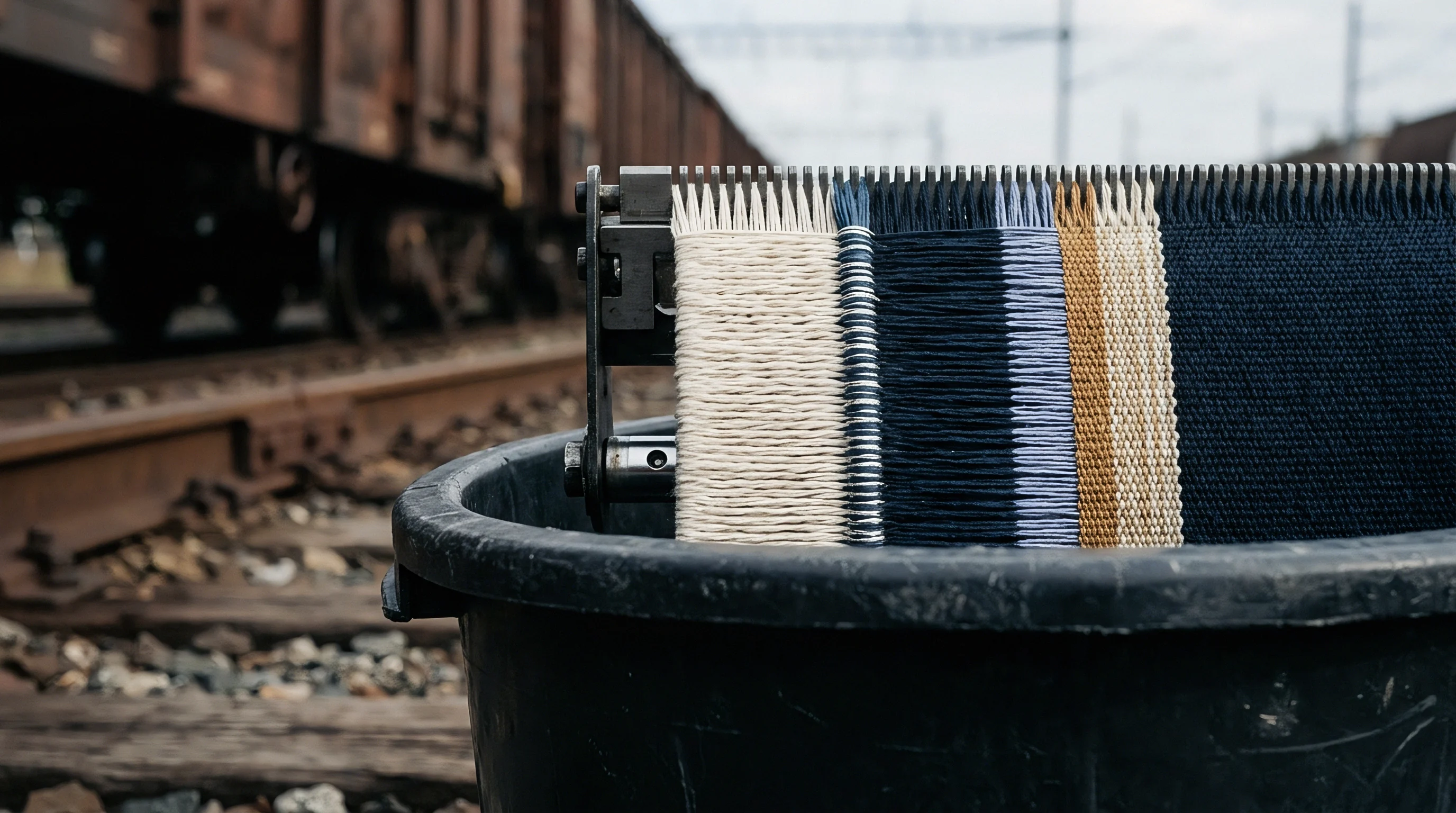
Relaxation processing in wet finishing releases residual manufacturing tension, allowing synthetic filaments to swell and contract laterally. During hot water scouring and stenter drying, thermal relaxation drives yarn bulk expansion, filling micro-voids between dent groups. However, if grey cloth reed marks are excessively severe, finishing relaxation cannot fully eliminate the structural memory of the wire gaps.
Spun cotton yarns exhibit limited post-weaving lateral swelling compared to textured synthetic filaments. Down-proof poplins constructed from high-twist spun yarns retain grey cloth dent marks through dyeing and calendering. Weave shed settings must achieve uniform thread distribution directly on the loom fell rather than relying on downstream wet finishing processes to obscure mechanical denting errors.
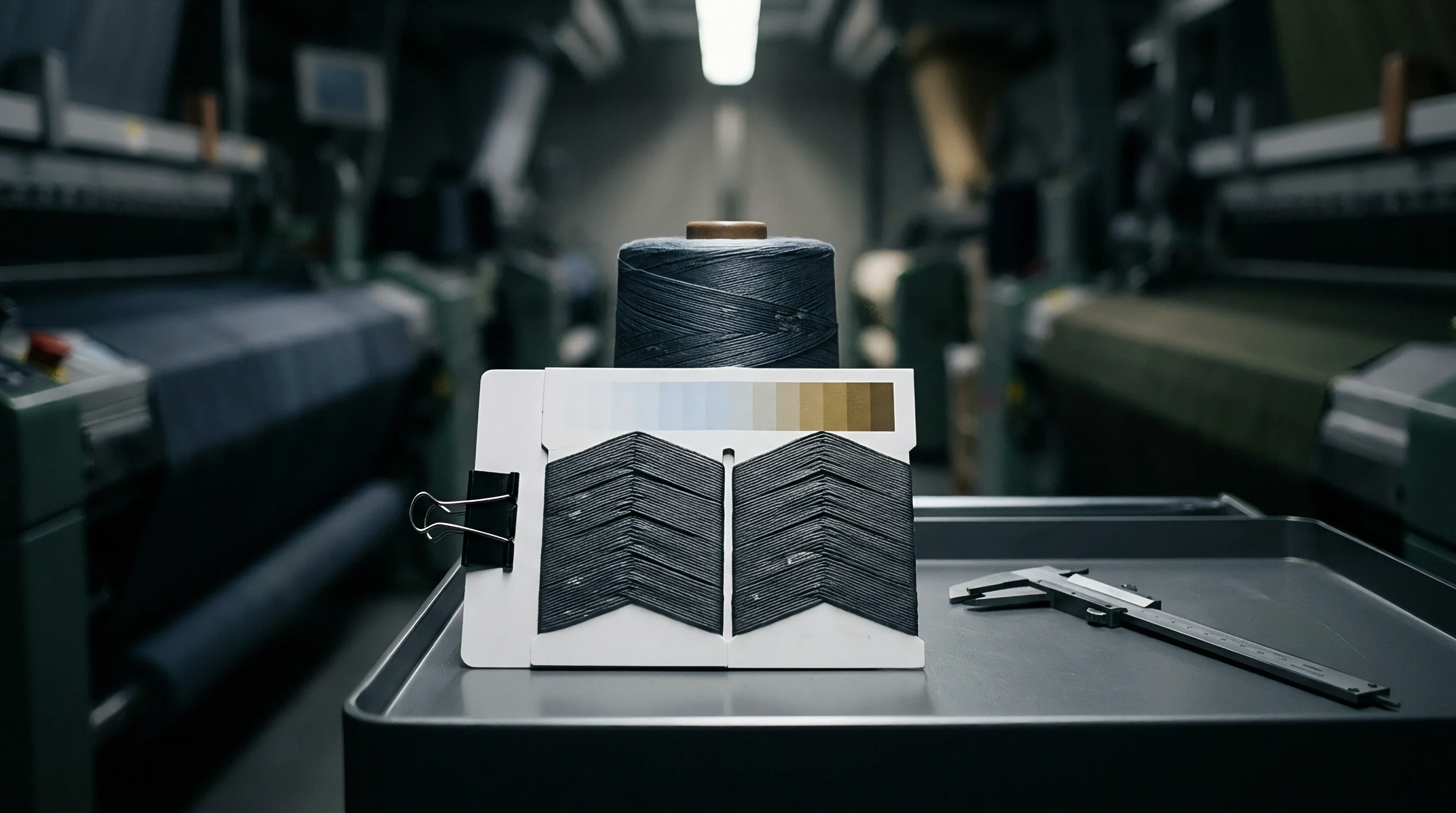
Does alternating the dent grouping sequence across the warp width prevent optical tracking without creating localized tension bands across the fell line?
Splay
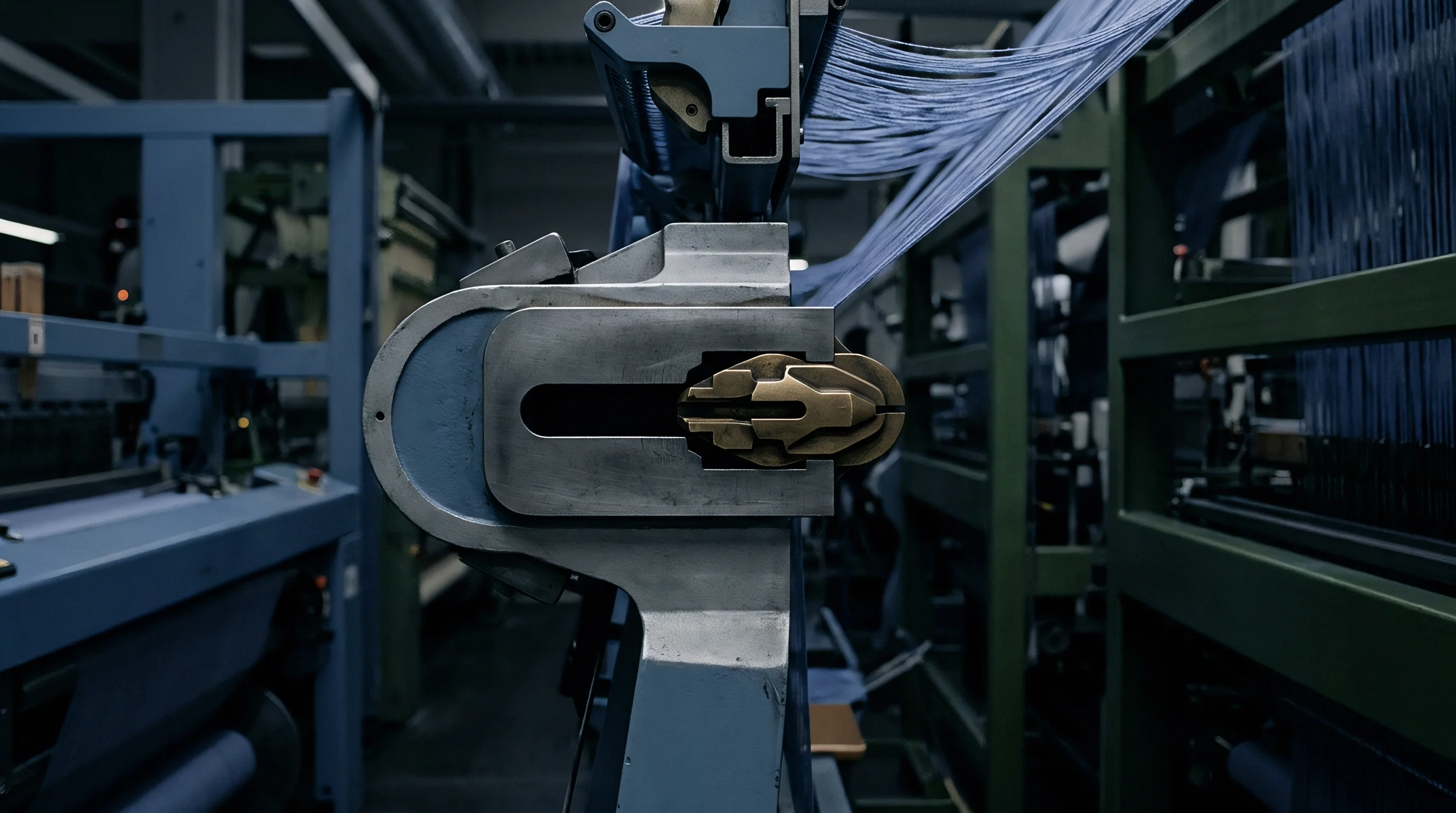
Warp threads do not travel parallel to the loom centerline across the entire weaving zone. Upon leaving the reed face, the woven cloth contracts in width due to pick crimp interlace, shrinking the cloth fell to a narrower dimension than the drawn reed width. This width difference forces outer warp threads to enter the fell at an oblique angle relative to the dent wires.
The angular displacement between warp end and reed split is defined as the splay angle.
Excessive splay snaps selvage threads. At splay angles exceeding two degrees, outer warp threads rub forcefully against the sharp edges of the dent wires during reed movement. This concentrated lateral scraping strips sizing material, weakens outer yarns, and causes frequent edge end breaks.
Controlling splay requires adjusting total drawn reed width relative to target off-loom cloth width.
Matching the reed dent distribution to the natural contraction of the fell prevents edge striping and reduces yarn fatigue at the selvage.
Fell Width Contraction and Splay Angles
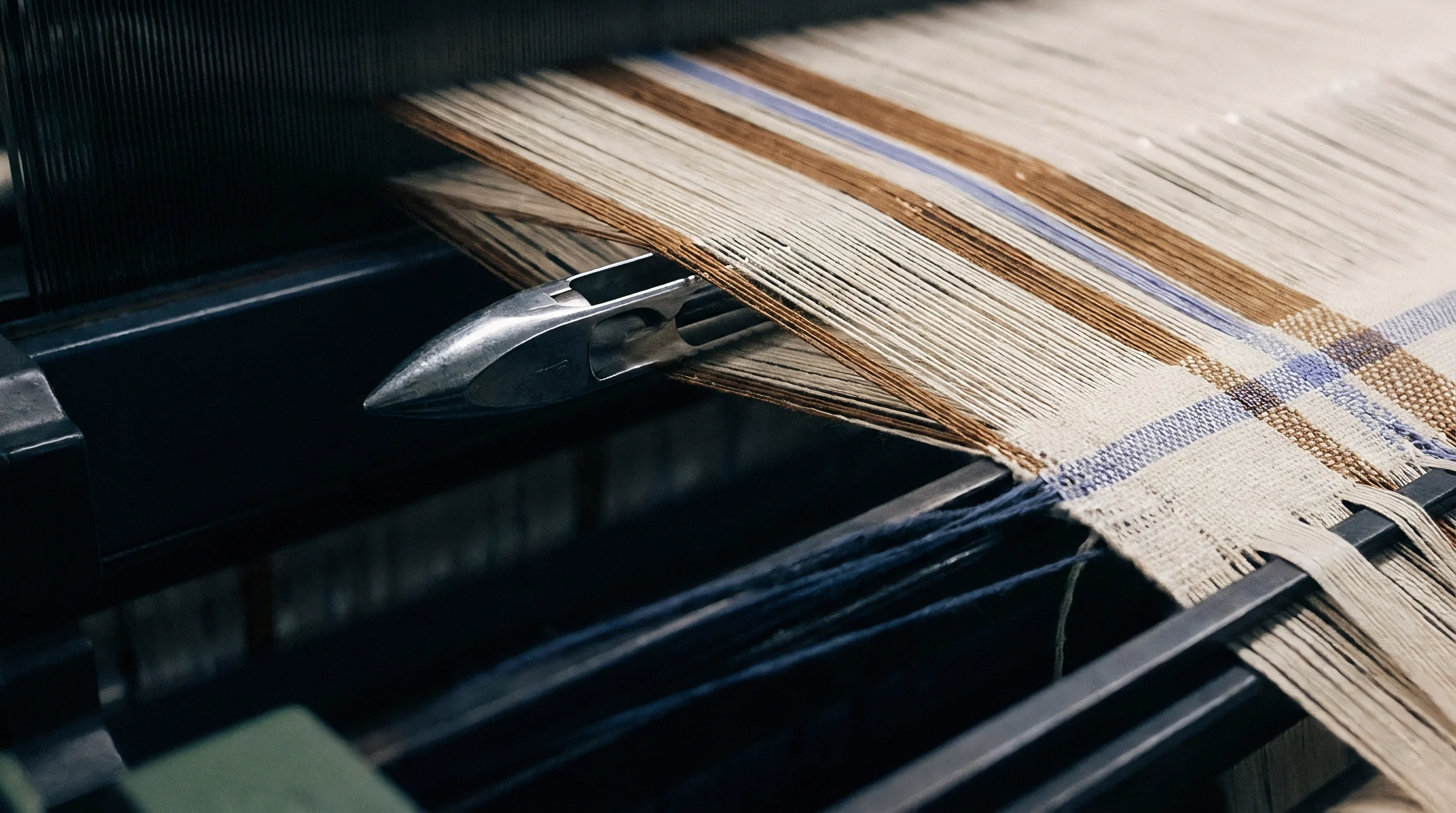
Calculating expected width contraction depends on weave interlace frequency, filling yarn elasticity, and warp tension. Plain weave high-density fabrics exhibit high width contraction due to maximum pick-by-pick interlace points. A 160-centimetre gray cloth may require drawing across a 168-centimetre reed width, creating four centimetres of contraction per side.
To reduce splay angles near the edges, weave technical managers use variable denting plans. Variable plans maintain standard ends per split across the fabric body while increasing dent count per centimetre near the selvages. Graduated denting accommodates edge contraction smoothly, preserving a zero-degree splay angle across eighty percent of the fabric width.

Temple Selection for High Density Fells
Temples stabilize the cloth fell line. Mechanical temple rings hold the fabric edges at a fixed width close to the reed sweep line, neutralizing excessive contraction forces before they transfer to outer warp ends. Selecting the correct temple configuration prevents selvage distortion in high-density constructions.
- Mount multi-ring cylinder temples equipped with spiked brass rings matching the fabric linear mass density.
- Set temple ring angle inclination to push cloth edges outward toward the loom drive side frame.
- Position the temple front edge within two millimetres of the reed back dead-center point without allowing physical metal-to-metal contact.
- Verify temple cover plate clearance to prevent clamping thread bundles during beat-up sweep.
- Inspect edge warp alignment visually under stroboscopic light to confirm splay angle remains below one degree at maximum loom operating speed.
Mill technicians frequently claim that wide reed splay can be ignored if heavy temple ring pinning is applied, but excessive temple grip leaves pin marks, tears fine synthetic selvages, and fails to prevent wire abrasion along outer body splits.
Formula
Deriving an exact reed plan for a high-density specification requires evaluating warp count, target finished ends, crimp loss, reed width, and open air space ratios within a unified mathematical sequence. The calculation workflow converts buyer-specified finished ends per unit measure into the actual physical dent density required on the loom floor.
Consider a representative high-density specification for a 400T down-proof nylon taffeta. Target finished parameters specify 90 ends per centimetre, 20 denier (22 dtex) fully drawn monofilament-like multifilament nylon 6,6 warp yarn, finished usable fabric width of 150 centimetres, plain weave structure. Total off-loom and finishing warp contraction is estimated at 4.5 percent.
Overall weave room processing allowances require establishing an exact plan that preserves loom operating efficiency above ninety percent.
Worked Derivation for down Proof Filament Taffeta
Calculating grey loom warp ends per centimetre accounts for total wet-finishing and heat-setting width contraction:
Grey Warp Ends per cm = Finished Ends per cm × (1 – Contraction Ratio)
Grey Warp Ends per cm = 90 × (1 – 0.045) = 85.95 ends per cm
Total warp ends across 150 cm grey cloth width = 85.95 × 150 = 12,892 body ends (excluding selvages). Adding 128 selvage ends gives a total warp count of 13,020 ends.
Next, evaluate denting configurations comparing 2-end, 3-end, 4-end, and 5-end plans to choose the optimum reed specification. Reed Number (dents per cm) is calculated as Grey Warp Density divided by Ends per Split:
Plan A (2 ends/split): 85.95 / 2 = 42.98 dents/cm (Reed No. 430 on 10cm basis)
Plan B (3 ends/split): 85.95 / 3 = 28.65 dents/cm (Reed No. 287 on 10cm basis)
Plan C (4 ends/split): 85.95 / 4 = 21.49 dents/cm (Reed No. 215 on 10cm basis)
Evaluating wire dimensions for Plan B (3 ends/split): A standard Reed No. 287 uses 0.16 mm wire thickness. Pitch = 10 mm / 287 = 0.0348 cm = 0.348 mm. Open gap width = 0.348 mm – 0.16 mm = 0.188 mm.
Air space ratio = (0.188 / 0.348) × 100 = 54.02 percent.
Calculated channel clearance for 22 dtex nylon: Yarn diameter d = sqrt(dtex / 9000 / density) / 10 ≈ 0.048 mm. Three parallel threads occupy 3 × 0.048 = 0.144 mm. Occupancy ratio inside open gap = (0.144 / 0.188) × 100 = 76.6 percent.
This occupancy ratio is dangerously high for high-speed air-jet weaving, indicating that a 3-end plan will induce excessive yarn abrasion.
Re-evaluating Plan C (4 ends/split): Reed No. 215 uses 0.20 mm wire thickness. Pitch = 10 mm / 215 = 0.465 mm. Open gap width = 0.465 mm – 0.20 mm = 0.265 mm.
Air space ratio = (0.265 / 0.465) × 100 = 56.99 percent. Four parallel threads occupy 4 × 0.048 = 0.192 mm. Occupancy ratio inside open gap = (0.192 / 0.265) × 100 = 72.4 percent.

Comparative Table of Denting Configurations
Comparing performance mechanics across theoretical plans highlights the optimum selection for production stability.
| Denting Scheme | Reed Count (Dents/cm) | Ends per Dent | Reed Mark Visibility Score | Beat-up Load (N/m) | Loom Efficiency (%) |
|---|---|---|---|---|---|
| 2 Ends / Dent | 43.0 | 2 | 1.0 (Imperceptible) | 1450 | 78.2 (High warp breaks) |
| 3 Ends / Dent | 28.7 | 3 | 2.5 (Slight) | 1180 | 88.5 (Moderate chafing) |
| 4 Ends / Dent | 21.5 | 4 | 3.5 (Acceptable) | 960 | 94.1 (Optimum balance) |
| 5 Ends / Dent | 17.2 | 5 | 4.8 (Severe lines) | 840 | 91.0 (Shedding delays) |
The four-end per split configuration balances air space percentage, reduces beat-up resistance force to 960 Newtons per metre, and maintains loom operating efficiency at 94.1 percent.
Standard purchase contracts governed by ISO 105-X12 fastness and ISO 13934 strength standards mandate that reed mark visual variances must not exceed Grade 4 on the grey scale after steam finishing, forcing suppliers to re-weave lots produced on incorrectly dented reed combs.

Yield
Loom efficiency, warp break frequency, air consumption rates, and machine downtime dictate the final conversion cost per finished metre. Choosing an overly aggressive reed plan to minimize reed mark lines often severely degrades loom productivity. High end packing per split increases warp friction, causing filament snapping and automatic loom stops.
Every warp stop requires operator intervention, adding labor costs and leaving start-up marks on high-density cloth fells.
Warp breaks lower weave room output. Running a loom shed at eighty percent efficiency due to improper denting calculations increases weaving energy costs by over eighteen percent per metre. Air pressure drives filling insertion.
In air-jet weaving, high warp packing density blocks main and relay nozzle air passage through the shed tunnel, requiring higher compressed air pressure to drive the pick across the fell width, inflating energy overhead.

Loom Efficiency and Air Jet Energy Consumption
Compressing air to power auxiliary nozzles accounts for up to sixty percent of a modern weaving plant’s total electrical expenditure. When warp ends crowd heavily inside coarse reed splits, fuzz and broken filaments obstruct the air channel formed by shaped reed wires. To maintain reliable filling insertion across an obstructed shed, compressor line pressure must be raised from 0.5 Megapascals to 0.65 Megapascals.
Operating at elevated air pressure increases compressor power consumption proportionally, adding direct monetary cost to every woven metre. Establishing an calculated denting plan with sufficient open air space preserves clear air flow channels through the profile reed, stabilizing filling insertion while keeping power demands low.

Conversion Costs across Production Runs
Quantifying conversion economics requires documenting reed setup changeover times, wire replacement schedules, and finished fabric rejection rates across production runs.
- Reed Profile Certification mandates verifying surface roughness Ra, wire thickness tolerances, and alloy composition before mounting on high-speed looms.
- Denting Chart Specification details exact thread allocation across body splits, graduated edge denting zones, and selvage harness thread counts.
- Air-Jet Insertion Profile Log records relay nozzle pressure settings, valve opening timings, and pick arrival angles matching the chosen reed channel depth.
- Fell Line Contraction Audit tracks off-loom grey width versus reed drawing width to verify that splay angles remain below maximum safety thresholds.
Finishing heat shrinks synthetic filament. Managing conversion margins on high-density woven fabrics requires balancing greige structural performance against loom shed productivity. Precision reed plans eliminate mechanical striping and lower energy consumption across high-speed weaving facilities.