Basic Warp Beam Tension Setup in Tricot Knitting Machines
Tricot warp beam tension setup balances linear runner lengths per rack using calibrated let-off drives and spring rails to stabilize fabric loop geometry.
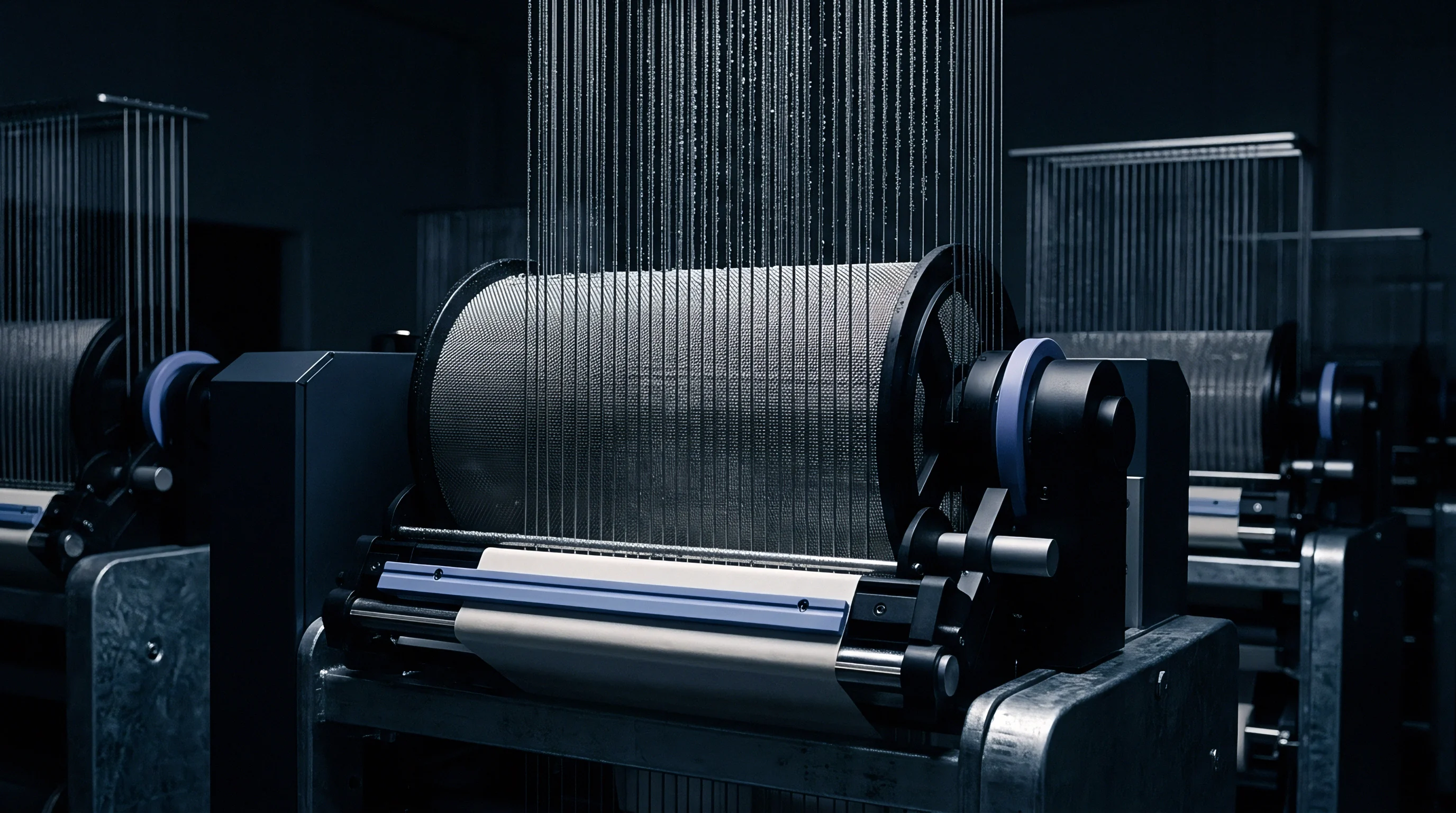
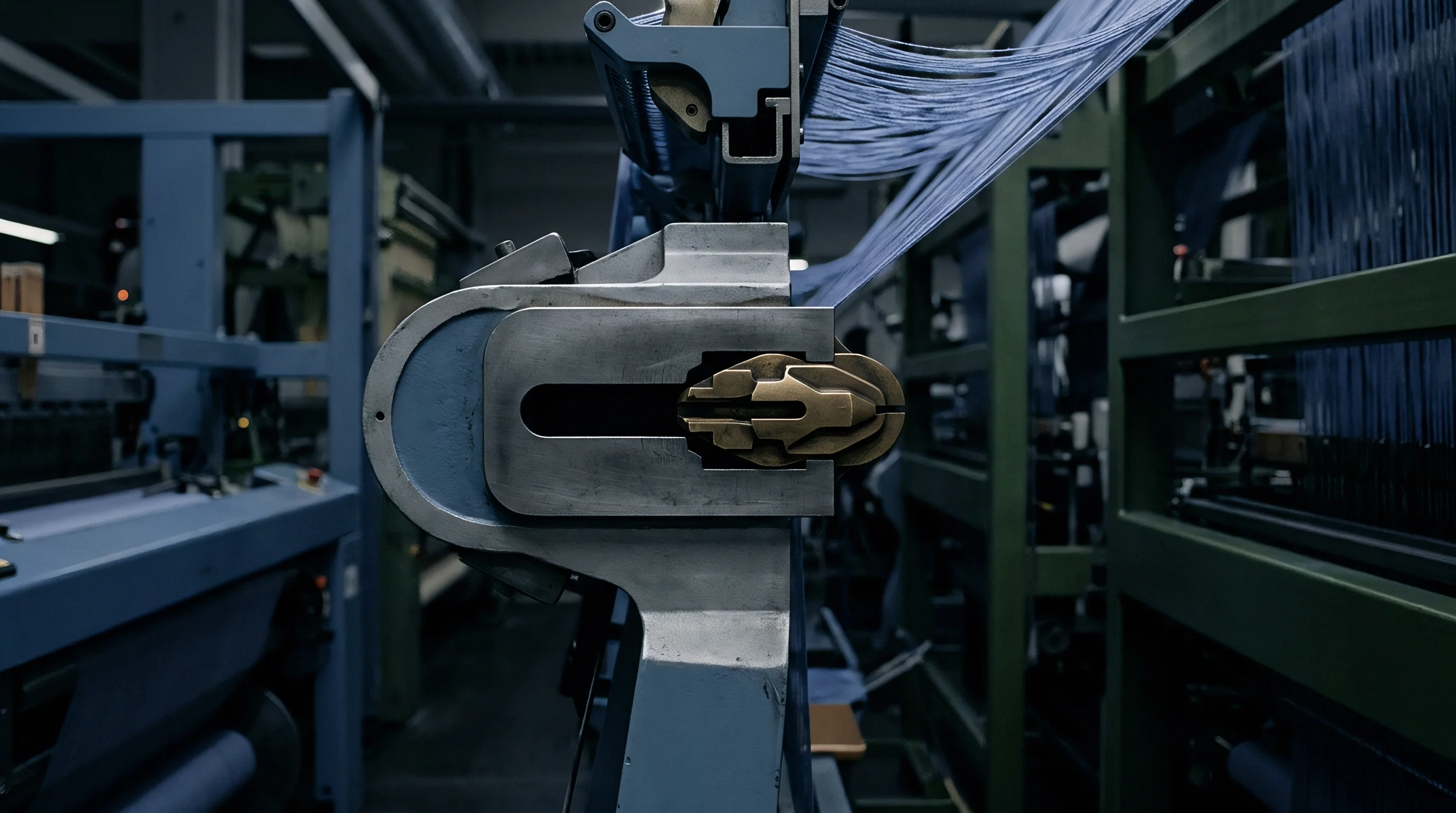
Runner
Knitting a stable two-bar or three-bar tricot structure begins with fixed linear yarn feed measurements rather than direct spool torque readings. In warp knitting terminology, the runner designates the precise length of warp sheet fed into the needles during one standard rack of 480 machine cycles. When the front guide bar and back guide bar pull differing lengths per stitch, their ratio determines loop shape, fabric density, structural elasticity, and greige areal weight.
Tension balances the stitch loop. If the back bar yarn delivers at excessive tightness relative to the front bar, the underlaps distort, pulling the needles backward out of vertical alignment with the sinkers. Conversely, an overfed warp sheet sags during the guide bar swing, causing yarn slack that snags on needle beards or compound needle sliders during cast-off.
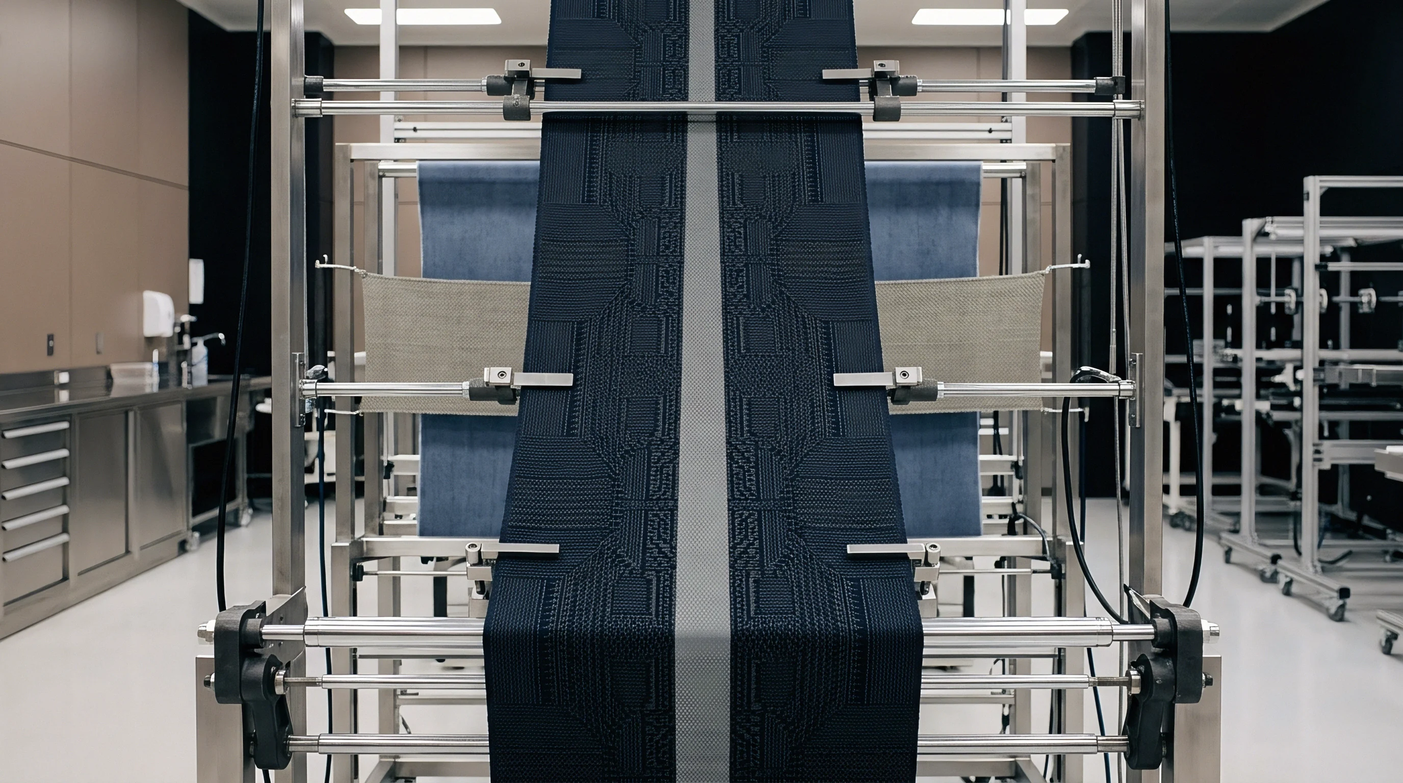
Rack Delivery Rates and Yarn Displacement
Mill specifications document the exact millimeter length per rack for each separate guide bar. On a standard 28-gauge tricot machine producing a standard plain jersey locknit construction with 44 dtex flat filament polyester, the front bar typically consumes approximately 1450 millimeters per rack while the back bar consumes 1100 millimeters per rack. This establishes a target feed ratio of 1.32 to 1.00.
The mechanical or electronic delivery drive rotates the warp beam to supply exactly those lengths regardless of whether the beam is completely full at 762 millimeters diameter or unwound down to its bare 152-millimeter aluminum core.
| Fabric Construction | Machine Gauge | Yarn Size Bar 1 | Yarn Size Bar 2 | Bar 1 Runner | Bar 2 Runner | Feed Ratio |
|---|---|---|---|---|---|---|
| Plain Locknit | E 28 | 44 dtex / 12 fil PES | 44 dtex / 12 fil PES | 1480 mm/rack | 1120 mm/rack | 1.32 : 1 |
| Reverse Locknit | E 28 | 44 dtex / 36 fil PA | 44 dtex / 36 fil PA | 1140 mm/rack | 1460 mm/rack | 0.78 : 1 |
| Tricot Satin | E 32 | 33 dtex / 10 fil PES | 55 dtex / 24 fil PES | 1620 mm/rack | 980 mm/rack | 1.65 : 1 |
| Two-Bar Mesh | E 28 | 78 dtex / 24 fil PES | 78 dtex / 24 fil PES | 1350 mm/rack | 1350 mm/rack | 1.00 : 1 |
| Powernet Base | E 28 | 44 dtex / 13 fil PA | 156 dtex Elastane | 1580 mm/rack | 420 mm/rack | 3.76 : 1 |
Warp tension operates as the reactive force resisting this feed. Centinewtons per individual end represent the physical unit evaluated on the line. For standard synthetic filament yarns, typical target tension values sit between 0.10 and 0.25 centinewtons per dtex.
Exceeding 0.30 centinewtons per dtex stretches the synthetic filament elastically before stitch formation, which induces immediate contraction once the finished greige cloth leaves the take-down rollers.
Stiffer beam flanges preserve uniform yarn delivery from edge to center.
Barrel deflection causes center sag. When wide beams spanning 2184 millimeters experience lateral inward deflection from winding pressures, the yarn packages at the flanges hold larger practical circumferences than the compressed center. Machine operators calculate their baseline runner setting from flange and center tape readings taken during initial thread-up.
The front bar carries the dominant structural load during loop knocking-over, so technicians verify front beam delivery before altering back beam let-off rates.
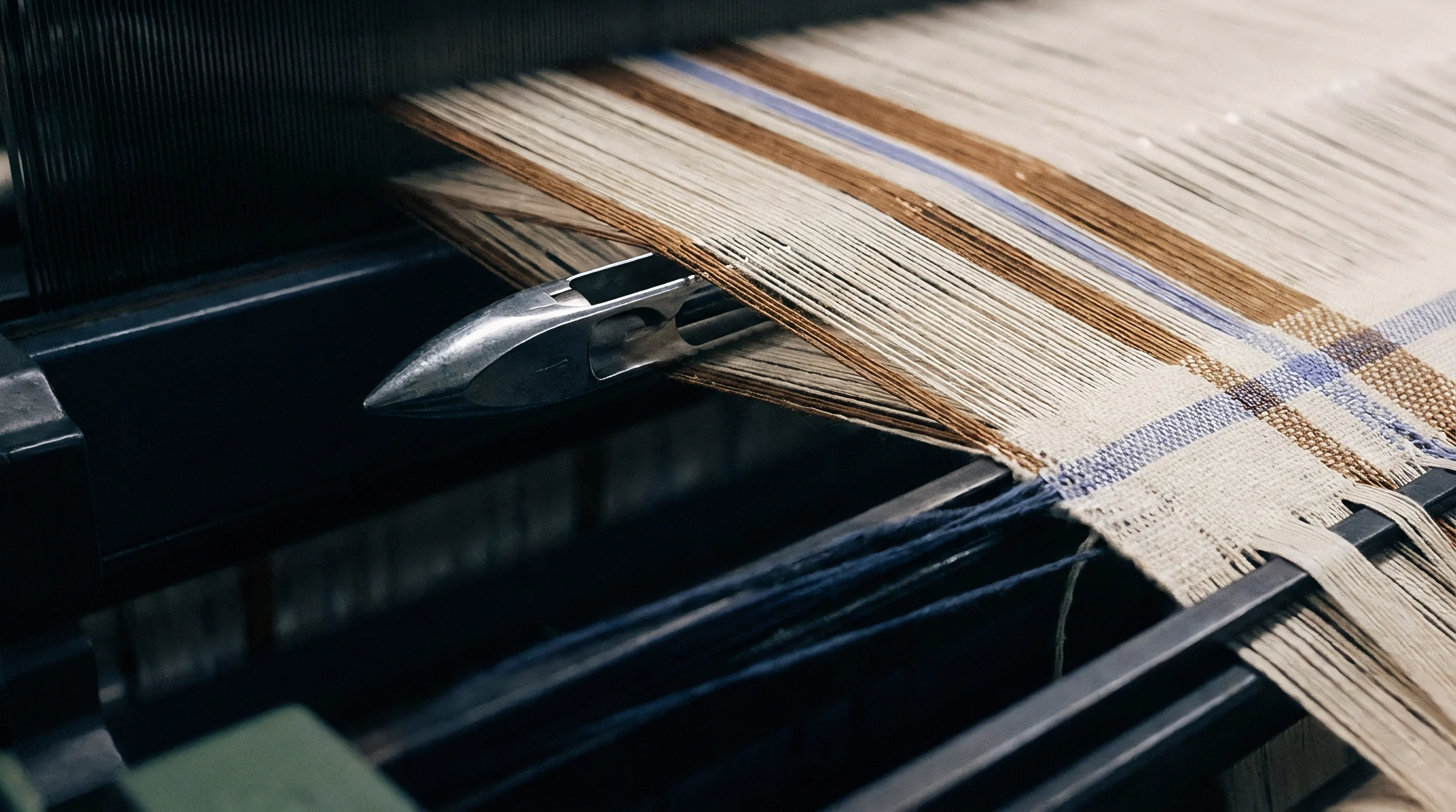
Loose threads invite needle strikes.
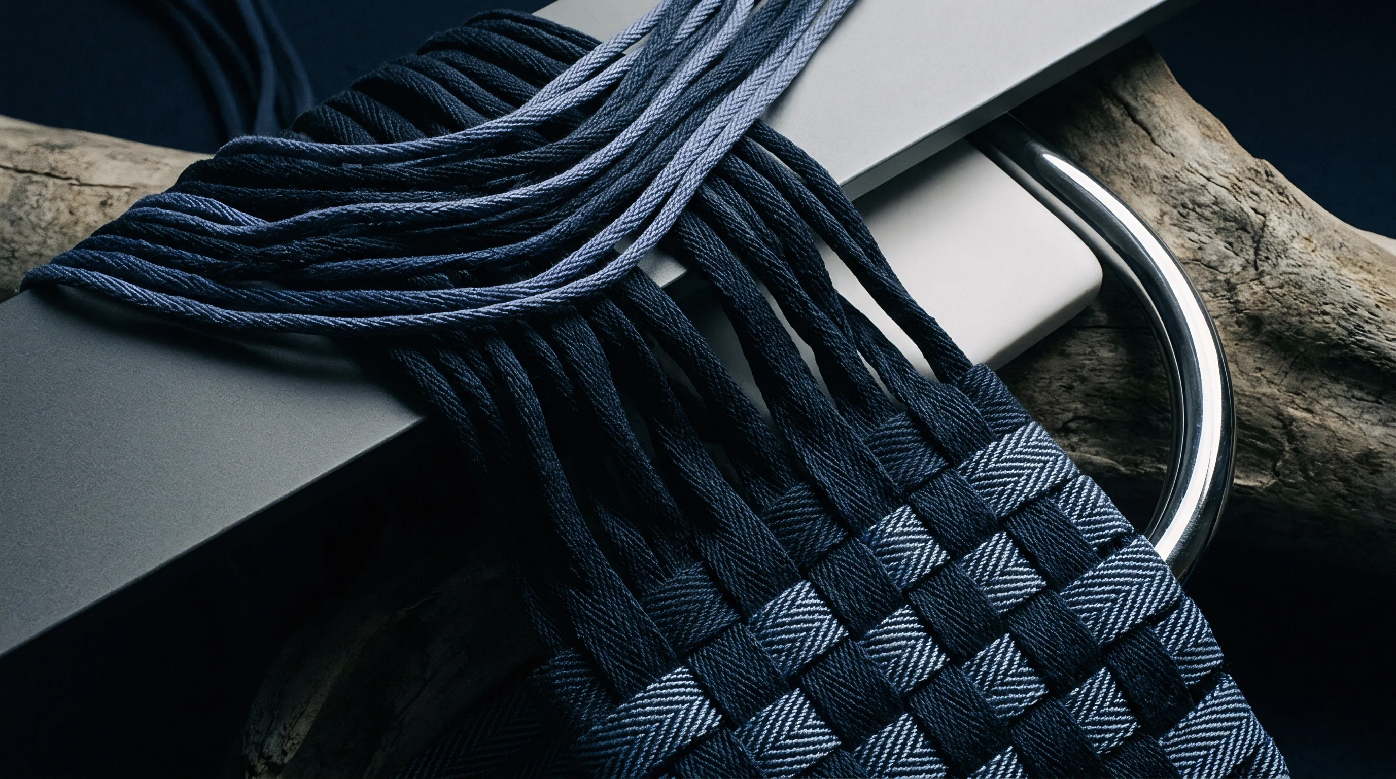
Letoff
Unwinding thousands of warp ends simultaneously demands precise rotational coordination as the package diameter diminishes. A standard 30-inch beam holds an outer diameter of 762 millimeters when fully wound with fully oriented polyester yarn, reducing to a core diameter of 152 millimeters when exhausted. Over the course of this single beam cycle, the shaft must accelerate its rotational velocity by a factor of five to maintain a perfectly invariant linear supply rate to the knitting zone.
Beam diameters dictate rotational speed. In older mechanical machinery, let-off relies on positive gear trains governed by variable PIV drives or friction brake bands driven by cam linkages connected to sensing feeler rollers. In contemporary high-speed equipment running up to 2500 courses per minute, computerized multi-axis servo drives power each beam shaft independently.
Does Electronic Letoff Eliminate Mechanical Cam Tracking?
Modern servo drives process feedback pulses from proximity sensors and load cells continuously. They modulate motor shaft revolutions every single machine cycle. The automated interface eliminates manual counterweight adjustments, though physical mass inertia remains an unalterable mechanical reality during machine start-up and emergency braking cycles.
The operational sequence for establishing baseline let-off requires sequential mechanical and digital calibration:
- Shaft engagement verification confirms that the beam chucks and expanding mandrels grip the beam arbor without rotational slippage under full operational motor torque.
- Diameter scanner initialization calibrates ultrasonic or optical distance sensors against known physical gauge blocks at maximum flange depth.
- Baseline gear ratio indexing maps the primary drive encoder pulses directly to the main needle crankshaft encoder to synchronize basic speed steps.
- Electronic runner entry transfers the target millimeter-per-rack figures from the specification sheet into the terminal controller memory.
- Dynamic inching validation runs fifty consecutive racks at 150 revolutions per minute while the technician measures real-time yarn passage with an optical runner checker.
Rotational Acceleration across Barrel Depletion
Consider a 28-gauge machine running at 2000 revolutions per minute, producing a standard jersey with a front bar runner of 1500 millimeters per rack. At 2000 revolutions per minute, the machine turns 4.167 racks every minute. The front beam must feed yarn at an absolute linear velocity of 6250 millimeters per minute, which equals 6.25 meters per minute.
When the beam is full at a diameter of 762 millimeters, one shaft revolution releases approximately 2394 millimeters of warp sheet. The beam shaft turns at 2.61 revolutions per minute. When the package depletes to its 152-millimeter bare barrel, one shaft revolution releases only 477 millimeters of yarn.
The motor must now turn that same shaft at 13.10 revolutions per minute. If the let-off control lags behind this acceleration curve, linear feed collapses, pulling the warp taut.
Tension across 44 dtex polyester filament stabilizes at 0.18 centinewtons per dtex when the guide bar swing operates at 2200 revolutions per minute.
Flange pressure warps the yarn package. Tension spikes observed midway through a beam unwind sequence routinely trace back to inconsistent density created during the sectional warping process. Warp preparation mills frequently attribute tension band striping on the knitting frame to ambient room humidity fluctuations rather than acknowledged package hardness gradients.
Rail
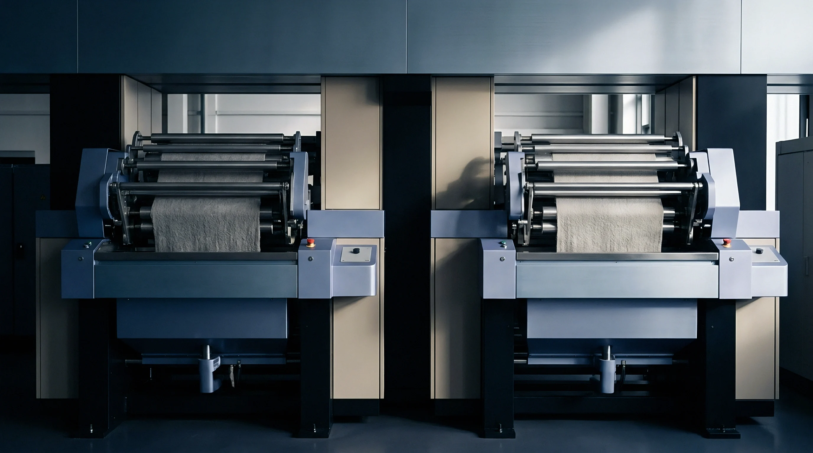
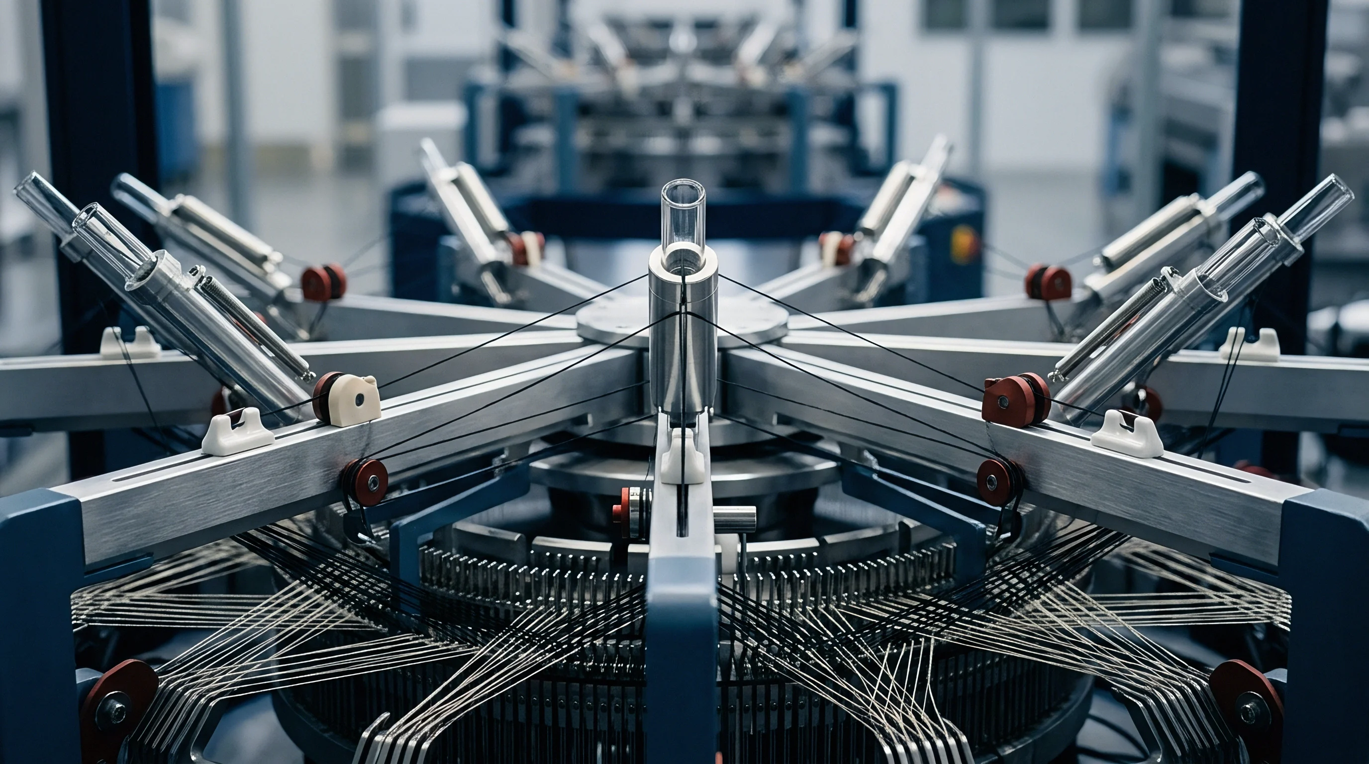
Positioned between the overhead warp beams and the guide bar hangers sits the tension rail assembly, often termed the spring bar or compensator bar. This polished steel or carbon-composite tube spans the entire working width of the machine, contacting every single end in the warp sheet. The bar absorbs the violent cyclic yarn demand generated by the knitting elements.
During each single revolution of the main shaft, needles rise, sinkers push forward, guide bars swing through the needle spaces, execute their overlap shog, swing back, and execute their underlap shog. Yarn demand is intermittent. Maximum yarn draw occurs during the overlap swing and loop knock-over, while minimum demand occurs as the needle descends to its lowest dwell point.
The spring-loaded rail flexes downward to surrender stored yarn during peak demand and springs upward to take up slack during the dwell phase.
What Displaces the Dynamic Equilibrium across Racks?
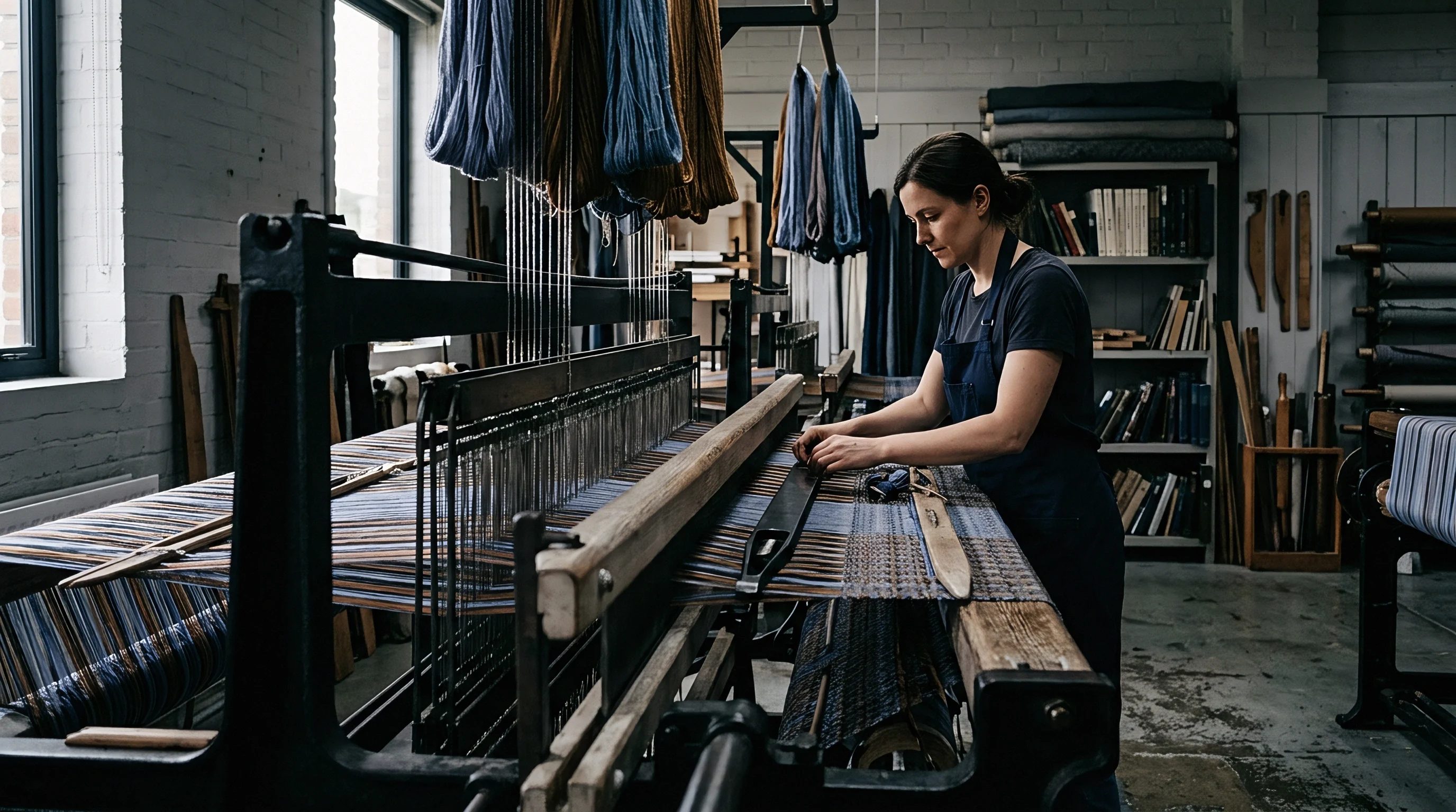
Static balance established at zero machine velocity alters drastically once the machine accelerates to full running tempo. Yarn inertia, guide bar stroke acceleration, and air drag alter the deflection amplitude of the compensator system. If the internal torsion springs inside the rail support blocks lack sufficient pre-load, the rail enters harmonic resonance with the main shaft frequency.
| Substrate Class | Linear Density | Operating Speed | Rail Spring Rate | Deflection Pre-Load | Static Yarn Tension |
|---|---|---|---|---|---|
| Polyester Fully Oriented Yarn | 33 dtex / 12 fil | 2400 rpm | 1.8 N/mm | 6.5 mm | 4.5 to 6.0 cN/end |
| Polyamide High-Filament | 44 dtex / 34 fil | 2200 rpm | 2.2 N/mm | 8.0 mm | 6.0 to 8.5 cN/end |
| Textured Microfiber PES | 55 dtex / 72 fil | 1800 rpm | 2.5 N/mm | 9.5 mm | 8.0 to 11.0 cN/end |
| Elastomeric Monofilament | 44 dtex bare | 1600 rpm | 0.8 N/mm | 14.0 mm | 1.8 to 2.5 cN/end |
| Viscose Continuous Filament | 66 dtex / 40 fil | 1500 rpm | 3.0 N/mm | 7.0 mm | 9.0 to 12.5 cN/end |
Yarn breakage halts production immediately. When resonance develops, individual warp ends bounce violently off the rail surface, crossing adjacent ends and entering guide eyes under wildly fluctuating drag angles. Mill auditors observe these tension-induced anomalies directly on the needle bar as dropped stitches and cut loops.
Spring Deflection and Torsional Resistance
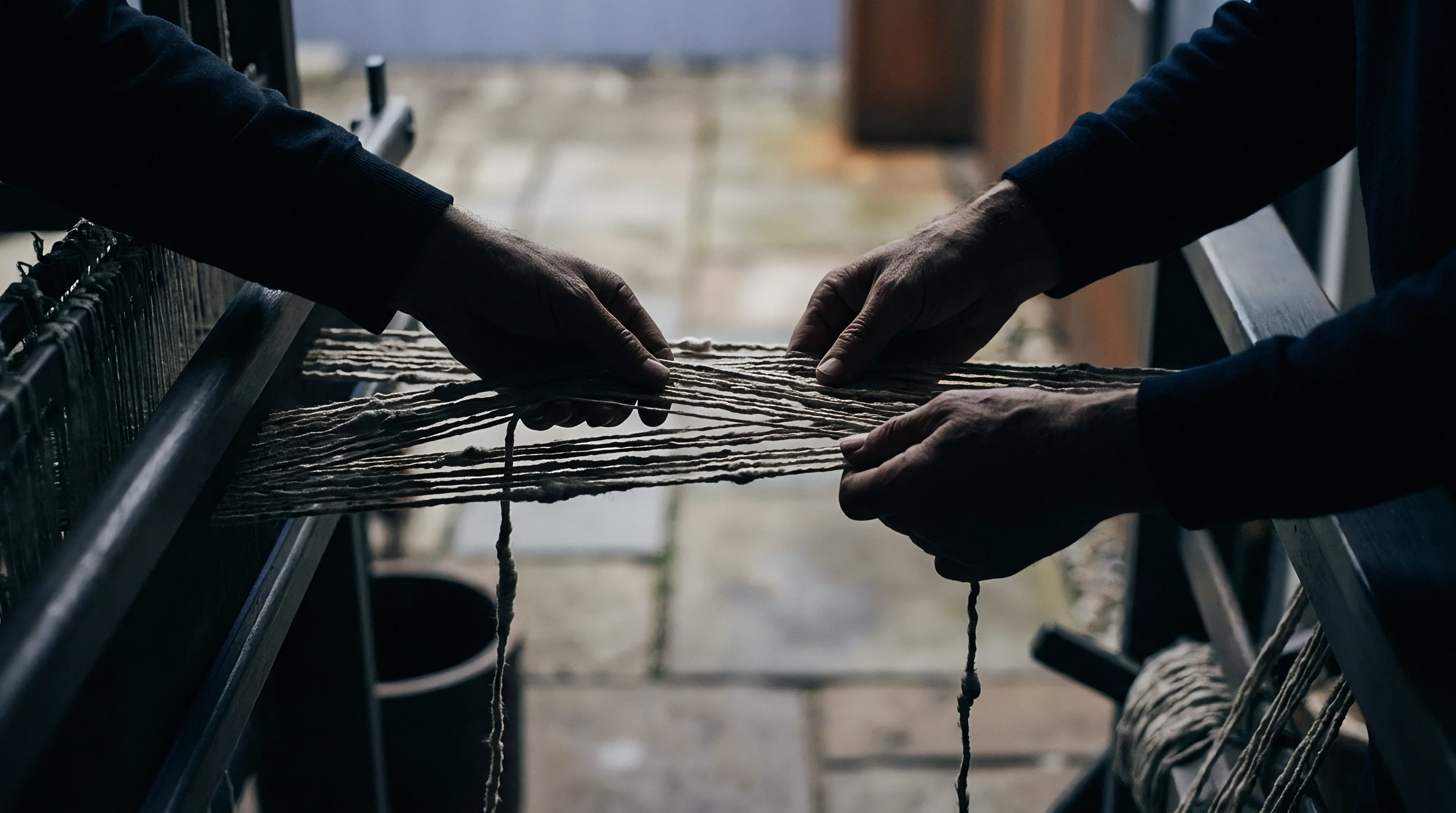
Adjusting the tension rail requires balancing static mechanical spring tension against electronic load cell sensors mounted at the pivot arms. Incorrect mechanical baseline settings produce definitive physical defects across the fabric face:
- Excessive spring pre-load exerts persistent over-tension on delicate microfibers, creating filamentation and fuzz balls inside the guide eyelets.
- Insufficient torsional stiffness allows the rail to bottom out against its lower mechanical bump stops during the guide overlap cycle, causing needle bending.
- Uneven left-to-right collar clamping yields unequal spring travel across the width, generating structural density variations between left and right selvages.
- Contaminated pivot bearing housings introduce mechanical hysteresis into rail deflection, resulting in lag between fabric take-down and let-off compensation.
Electronic load cells monitor dynamic pull. Sensors continuously translate mechanical displacement into millivolt feedback loops read by the let-off software. Setting the pre-load too stiff blinds the sensor to subtle runner variations, preventing the servo motor from making microscopic feed corrections.
Setting the pre-load too loose causes the motor to constantly hunt, producing transverse cyclic bands known on inspection tables as tiger stripes.
Mechanical friction brakes accumulate lint and drift out of calibration over long shifts.
Incorrect spring rail pre-load settings accelerate wear on needle guides, trigger micro-cracks in guide units, and lead to whole-machine shutdowns that cost hundreds of dollars per hour in dead capacity.
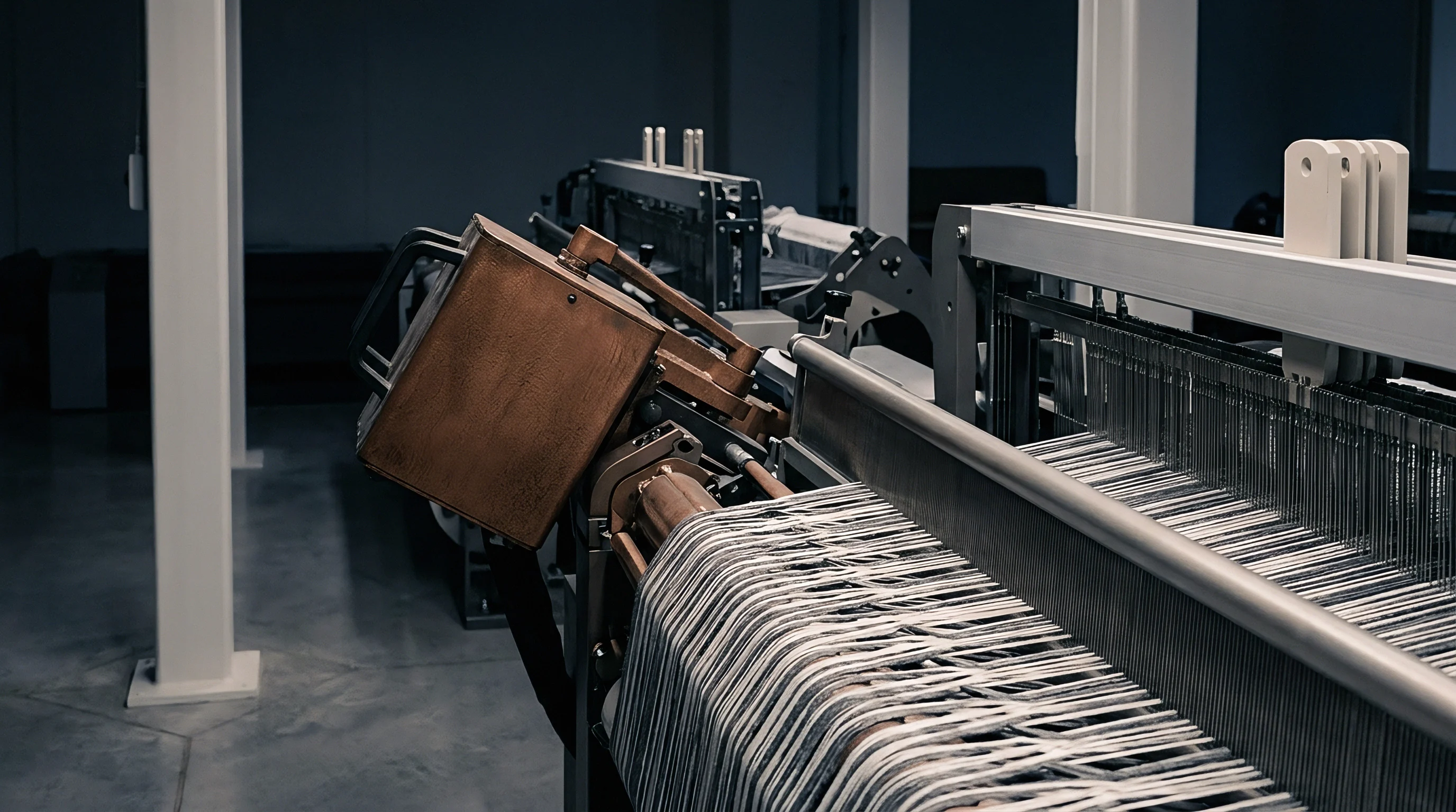
Distortion
Greige fabric defects originating from faulty warp beam tension rarely appear as localized tears. Instead, they manifest across whole fabric bolts as structural density distortions, diagonal skew, and optical shading differences. Tension determines how deeply the underlap pulls across adjacent wales.
When guide bar tensions fight each other, the resulting textile internal stresses remain locked until wet processing releases them.
Low draft leaves loops loose. An under-tensioned back bar allows underlaps to float loosely on the technical back, while the front bar stitches pull the entire textile into a distorted, single-faced geometry. Once submitted to high-temperature jet dyeing, the unequally tensioned synthetic filaments shrink at divergent rates, exposing severe structural barre across every finished roll.
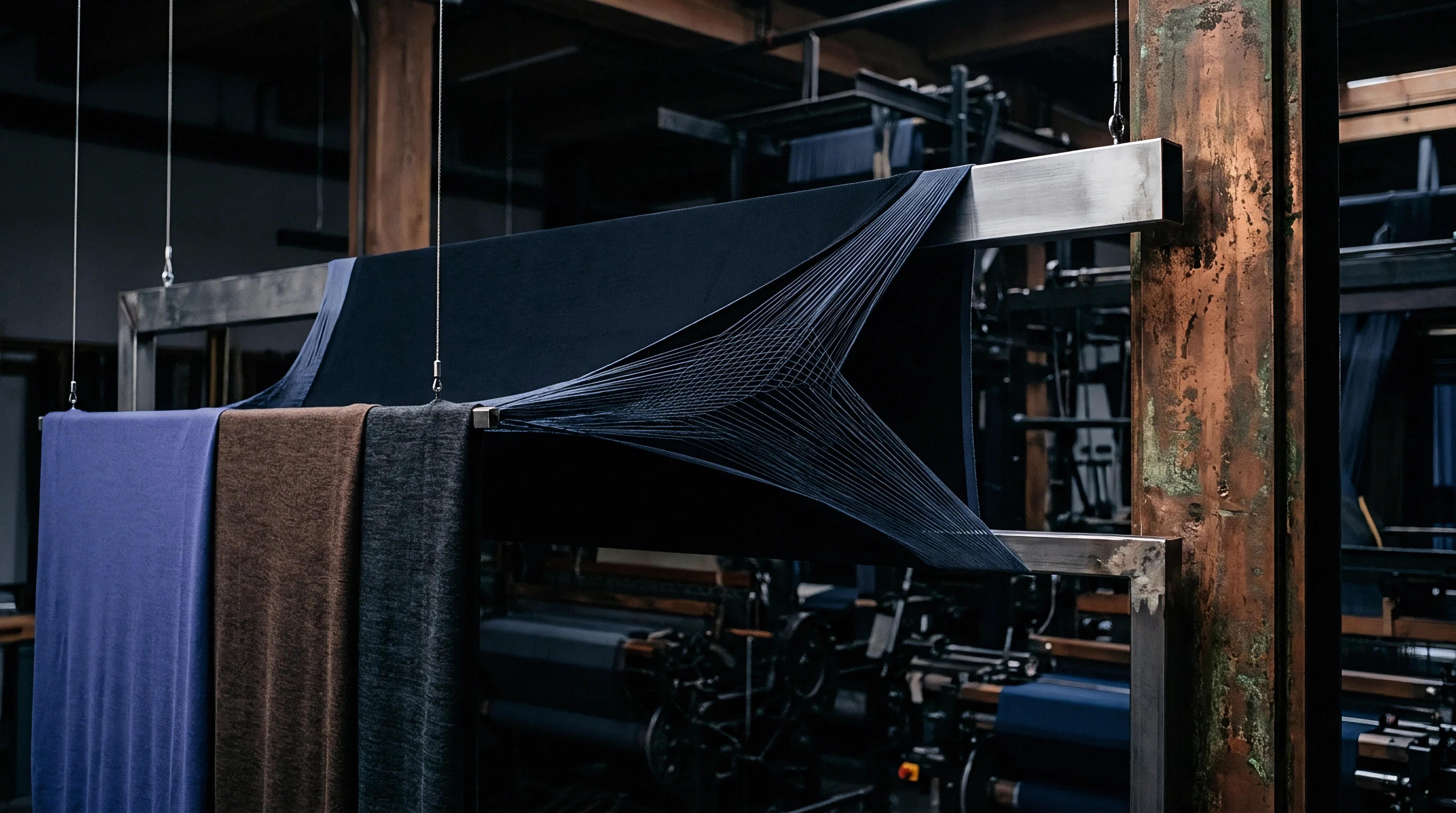
Structural Faults Induced by Uneven Draft
Tension variations between beam spools across the same guide bar shaft create vertical bands along the cloth length. In tricot production, a single knitting bar is frequently supplied by three or four separate sectional warp beams mounted end-to-end on a single spindle core. If spool number two was wound with two percent higher yarn tension than spool number one during warping, its yarn ends enter the knitting zone with lower latent elongation.
Needle strikes shatter guide points. When high-tension bands lift needles out of their precise paths, descending sinkers shear guide heads, destroying tooling worth thousands of dollars. The audit trail on finished goods begins with strict parameter checking at the knitting machine frame:
- Stitch density validation records wales and courses per centimeter on greige fabric under conditioned relaxation according to ISO 7211 standards.
- Single-end tension surveying utilizes a calibrated digital tensiometer across twenty randomized points per beam sheet to guarantee tension spreads stay inside plus or minus five percent.
- Runner length verification demands physical grease-thread marking across 480 needle cycles to confirm the true consumed length matches electronic display readouts.
- Sectional beam circumference profiling checks diameter tolerances with a steel vernier tape to prevent diametrical variance exceeding two millimeters between adjacent beam spools.
Spin Finish Friction across Guides
Yarn chemistry interacts directly with machine guide contact surfaces. Synthetic yarn producers apply spinning finishes, primarily mineral oils and antistatic esters, at levels ranging from 0.8 percent to 1.5 percent by weight to aid processing. When ambient knitting room temperatures exceed 26 degrees Celsius or relative humidity drops below 55 percent, friction coefficients between the filament surface and the polished matte chrome tension rail increase significantly.
High tension shears the needle beard. This thermal and frictional drag effectively multiplies beam delivery tension by fifteen to twenty-five percent before the yarn even touches the guide eyelets. A setup that produced immaculate cloth during night-shift conditions can generate catastrophic loop distortion by mid-afternoon if environmental controls fail to stabilize the yarn lubricity profile.
Whether modern high-speed cameras can isolate the microscopic dynamic drag differences between individual ceramic guide eyelet alloys remains an active dispute on factory floors.
Balance
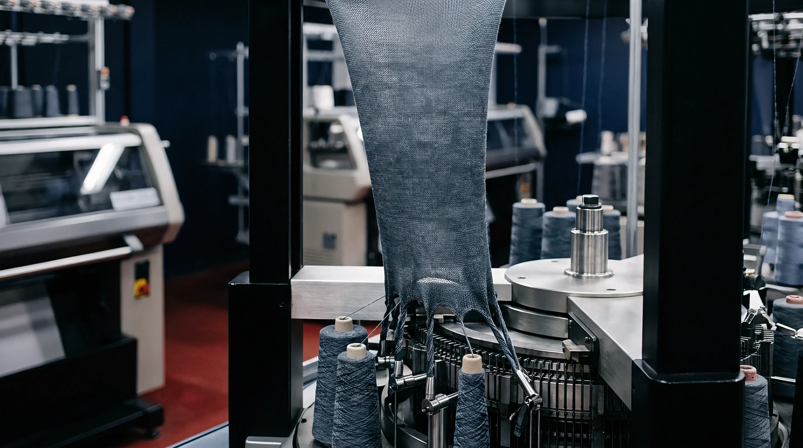
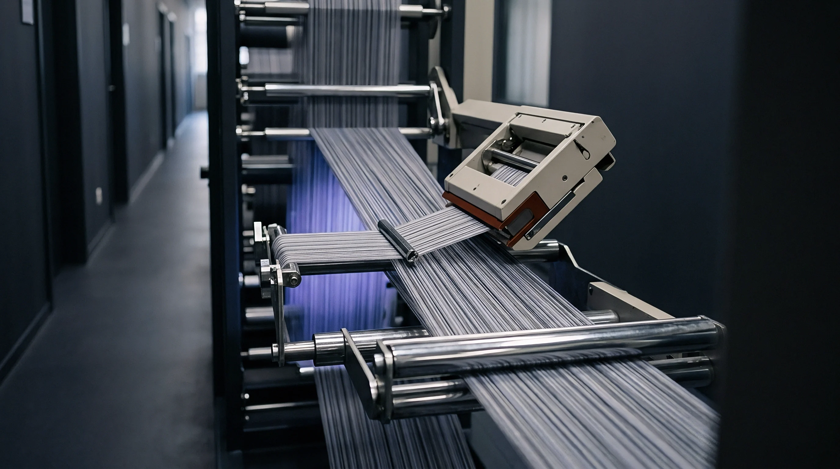
Achieving total equilibrium across multiple warp beam shafts represents the ultimate commercial hurdle in high-speed warp knitting. A two-bar tricot machine operates with two distinct warp sheets feeding the needle bed simultaneously. Because runner lengths differ between bars, yarn consumption rates diverge predictably.
If a locknit construction requires 1450 millimeters on bar one and 1100 millimeters on bar two, the front beam empties thirty-two percent faster than the back beam unless beam warping lengths were meticulously calculated in advance.
Empty cores create unrecoverable waste. If a mill mounts identical yarn lengths on both beams, the front beam empties completely while the back beam retains hundreds of kilograms of high-grade synthetic filament. Stripping partially filled warp spools ruins yarn package integrity, converting premium oriented filament into low-value greige scrap.
Simultaneous Core Runout and Beam Logistics
Production planners coordinate warp beam preparation so that all positions mounted on a machine deplete their packages within the same two-hour operational window. This simultaneous run-out minimizes machine changeover downtime. Splicing or replacing beams requires halting the knitting frame, cutting yarn sheets, securing ends, lifting out multi-ton steel shafts with overhead cranes, dropping in freshly warped beams, and re-threading thousands of microscopic guide eyes.
| Setup Configuration | Bar 1 Warp Length | Bar 2 Warp Length | Bar 1 Residual | Bar 2 Residual | Yarn Waste Total | Scrap Cost Impact |
|---|---|---|---|---|---|---|
| Equal Beam Warping | 35,000 m | 35,000 m | 120 m | 8,450 m | 242 kg PES | High |
| Proportional Calculation | 35,000 m | 26,550 m | 110 m | 135 m | 7 kg PES | Negligible |
| Imbalanced Tension Draft | 35,000 m | 26,550 m | 850 m | 2,100 m | 64 kg PES | Moderate |
| Over-Tensioned Back Bar | 35,000 m | 26,550 m | 95 m | 3,400 m | 98 kg PES | Elevated |
Mill technicians verify run-in every shift. When let-off settings drift unmonitored, the actual consumption diverges from the initial proportional warping plan. Running the back bar tighter than specified artificially suppresses its linear consumption, causing unexpected yarn excess on the back beam while the front beam runs dry prematurely.
Commercial Yield Specifications on Greige Cloth
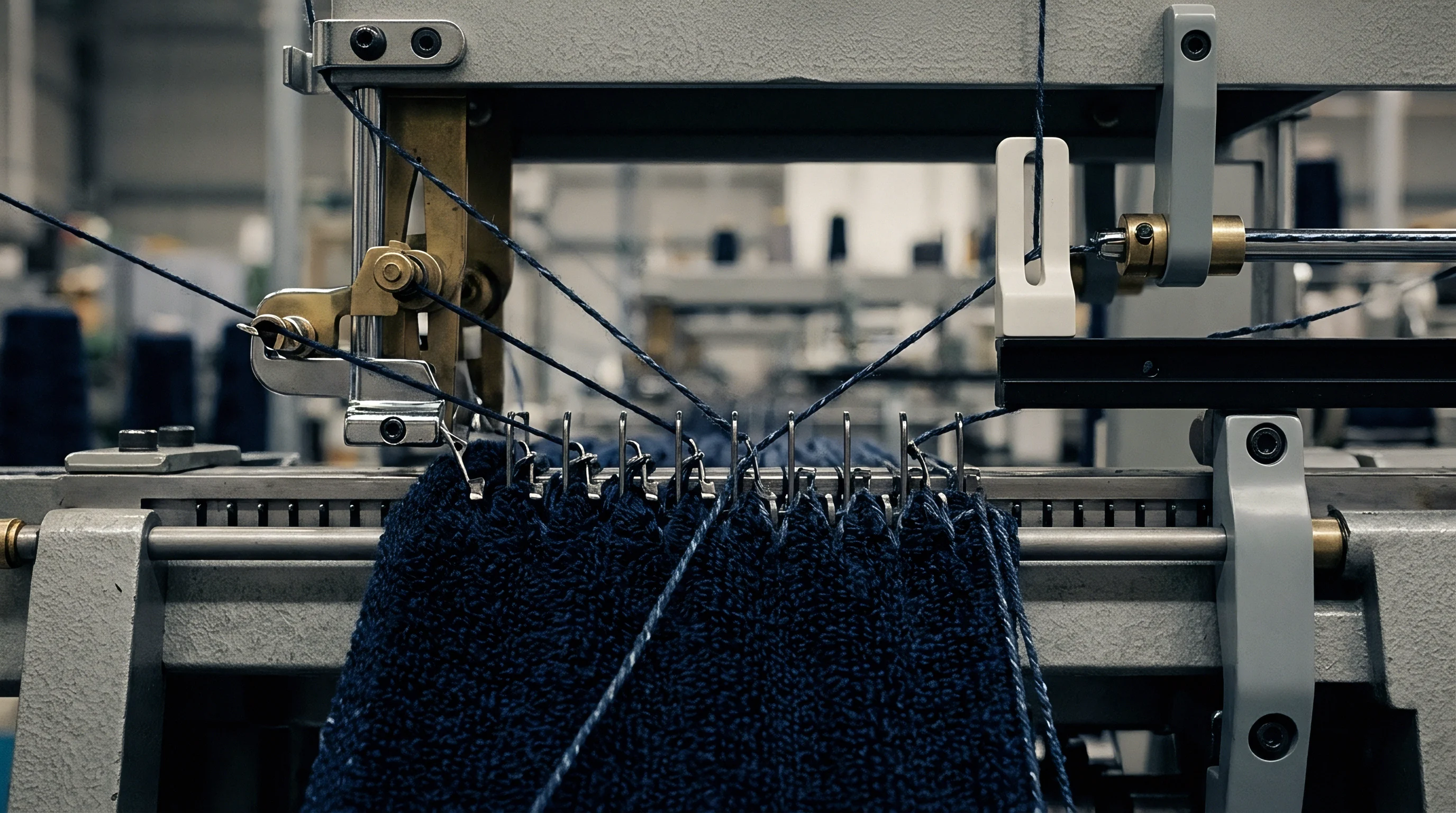
Fabric purchasing contracts specify narrow tolerances for greige courses per unit length, areal mass in grams per square meter, and finished cuttable width. If a warp knitting supplier runs beams under uncontrolled tension to inflate fabric yield per kilogram of raw yarn, the finished cloth fails dimensional stability testing upon first laundering.
Edge ends demand separate compensation. Selvage ends regularly experience higher frictional drag in the outermost guide units, leading to tight edges that curl inward and catch in downstream stenter pin chains. Progressive finishing houses address this by assigning independent auxiliary let-off drives to the outermost selvage spools or installing specialized low-friction ceramic eyelet blocks at the bed borders.
Failure to maintain runner ratios within two percent of the technical specification voids the buyer acceptance clause for finished course density.
Under international standard contracts, failure to meet stated course density tolerances triggers automatic financial penalties or outright container rejection at the buyer port of entry.