Calculating Loom Reed Width from Warp Crimp and Fabric Sett
Calculating correct loom reed width requires combining off-loom grey contraction, finished warp sett, and weft crimp percentage into one unified formula.
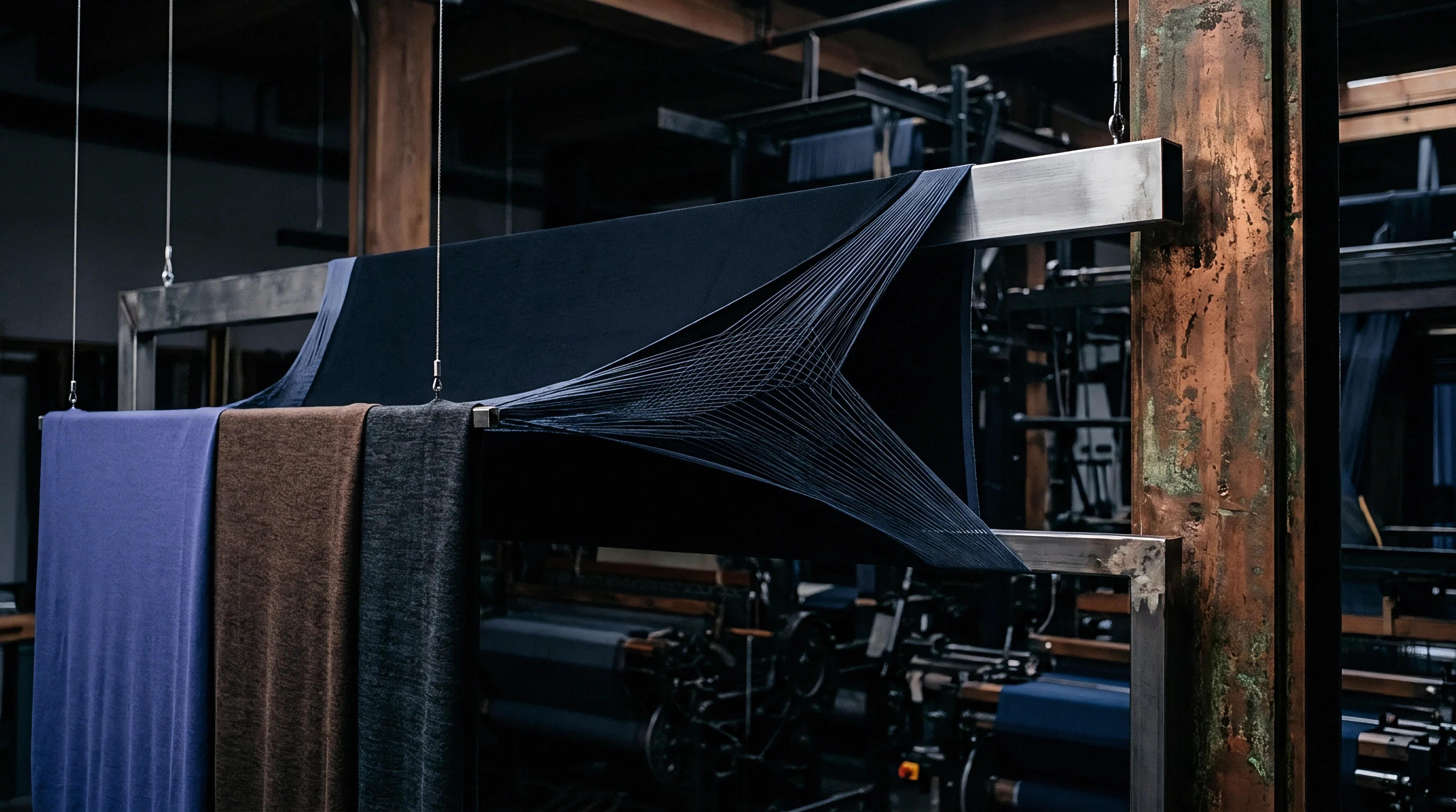

Geometry
Woven fabric gets its structural foundation from interlacing warp and weft under tension. When yarn leaves the loom shed and that mechanical strain drops, the cloth contracts immediately. Total pull-in depends on the yarn material, yarn count, weave pattern, and thread density per unit length.
Working out required reed space means tracing this contraction backward ~ moving from final target dimensions through wet finishing changes and off-loom relaxation to the loom shed itself.
Sett defines thread density, measured in warp ends and weft picks per unit length. Because the yarns interlace, neither set stays flat; each curves around the other to form the wavy geometry called crimp. Warp crimp accounts for the extra length of warp yarn required relative to the finished fabric length.
Weft crimp ~ or weft take-up ~ expresses the ratio between warp sheet width in the reed and grey fabric width off the loom. Yarn consumption follows directly from structure, and grey cloth contracts the moment loom tension drops.
Sizing reed space requires keeping weft crimp and warp crimp distinct. Warp crimp drives yarn purchasing weights and beam sizing, while weft crimp dictates width contraction during weaving. Across high-speed rapier looms, dynamic crimp values shift rapidly as the shed closes.
The relationship between off-loom grey width and total warp width inside the reed follows the weft contraction factor:
Grey Width = Reed Width (1 – Weft Crimp Percentage / 100)
Rearranging the identity gives the reed width required for a target grey width off the loom harness:
Reed Width = Grey Width / (1 – Weft Crimp Percentage / 100)
Weft crimp cannot be pulled blindly from historical tables. It fluctuates with the ratio of warp ends to weft picks, yarn linear density, twist multiplier, tension, and weave structure. A dense plain weave interlaces at every crossover, forcing the weft over and under adjacent warp ends in steep undulations.
That longer path creates high weft crimp and heavy width contraction off the reed. By contrast, a 3/1 twill or 5-shaft satin has fewer interlacing points per unit area, letting the weft lie flatter across the warp sheet with lower crimp and less shrinkage on the loom floor.
A combed cotton 3/1 twill woven at 40 picks per centimetre demonstrates a warp crimp factor of 8.5 percent under standard atmospheric conditions of 20 degrees Celsius and 65 percent relative humidity.
Getting accurate grey warp and weft crimp values requires lab testing on unraveled yarn samples under standard pretension loads. Relying on estimates instead of physical tests risks off-spec fabric widths, excessive selvage trimming, or rolls that fall short of garment cutting markers.

Standard Method for Laboratory Crimp Determination
Reliable reed width calculations rest on physical testing of yarn samples taken from trial runs or identical constructions. ISO 7211-3 defines the standard procedure for determining yarn crimp in fabric, establishing reproducible tension parameters that eliminate operator error.
- Cut five rectangular fabric strips measuring 50 millimetres wide by 300 millimetres long, taking specimens parallel to the warp and weft directions at least 100 millimetres away from the selvages.
- Mark a reference distance of exactly 250 millimetres across the center of each test specimen using a fine-point permanent marker while the fabric lies flat without tension on a smooth surface.
- Unravel ten individual yarns carefully from each specimen, securing the free ends without adding twist or stretching the fibers.
- Mount each yarn into the clamps of a direct-reading crimp tester equipped with an adjustable tensioning weight mechanism.
- Apply a standardized pretension calculated from yarn linear density, typically 0.5 centinetwons per tex for spun yarns and 0.75 centinetwons per tex for continuous filament synthetic yarns.
- Record the extended length of the straightened yarn between the reference marks on the scale of the crimp tester.
- Calculate the crimp percentage for each yarn specimen using the standard equation: extended yarn length divided by original fabric length, minus one, multiplied by one hundred.
- Average the ten readings for warp and weft directions to establish the mean crimp percentage for structural calculation models.
Friction alters warp tension as yarn linear density increases at a constant sett, where thicker yarns force greater physical displacement at every crossover point. That interaction raises weft crimp even when mechanical loom settings stay untouched. Calculating reed width without measuring actual crimp behavior for specific yarn lots leads straight to width errors at the garment factory.
Packing heavy filling yarns tightly into a fine warp sheet forces the filling to bend while the warp stays comparatively straight. This filling-up ~ or weft-dominant ~ crimp increases width contraction significantly. Conversely, a dense, high-tension warp beam forces the warp ends to absorb structural bending, leaving the weft flatter.
In that warp-dominant setup, weft contraction stays low and off-loom grey width remains closer to physical reed width. Calculating reed width depends on knowing which yarn set absorbs the structural crimp once tension releases at the reed.
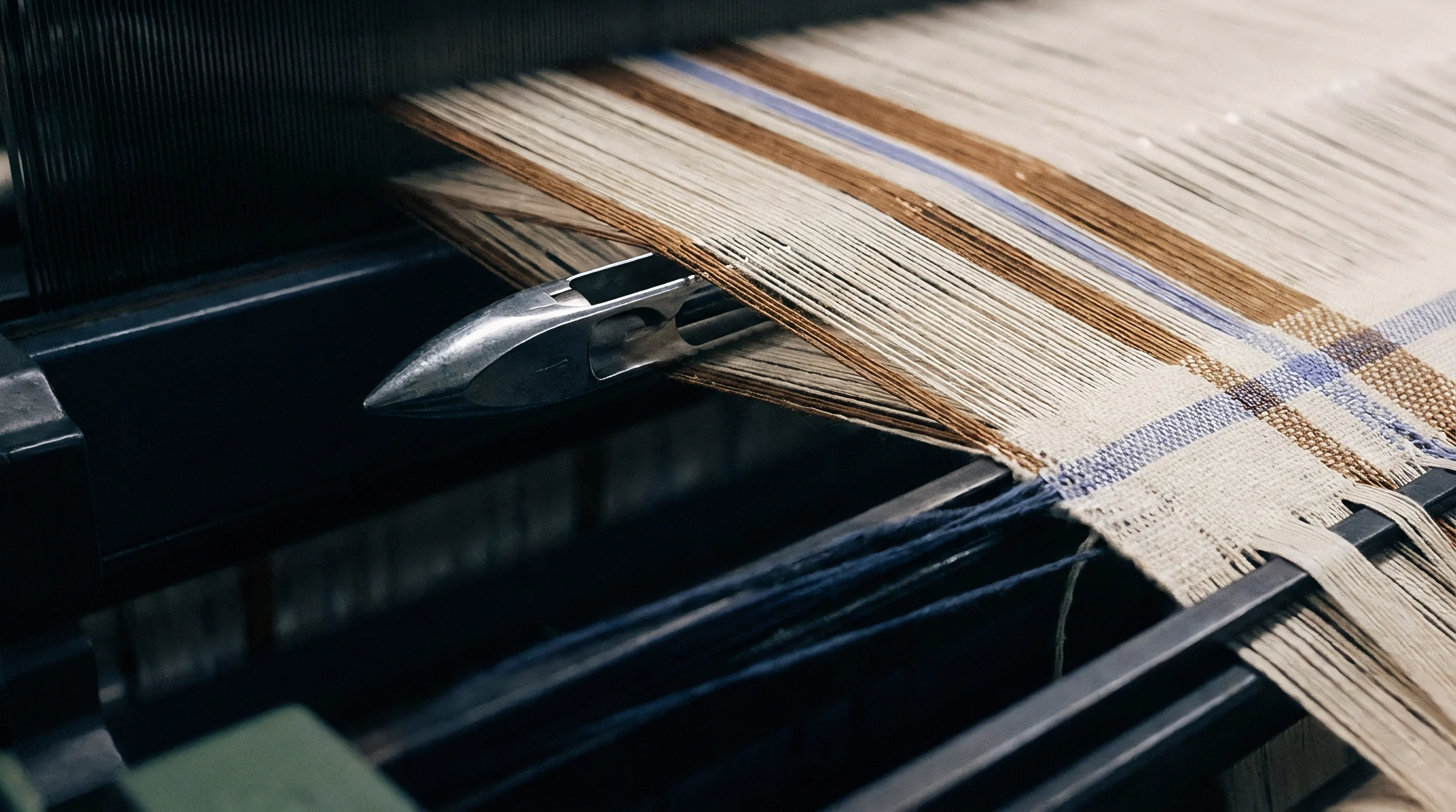

Shrinkage
Grey fabric off the loom does not reflect finished cloth dimensions. Subsequent wet processing ~ scouring, bleaching, mercerization, continuous dyeing, drying, and functional finishing ~ alters both warp and weft dimensions. Heat setting continuous filament synthetics relaxes internal stresses and triggers thermal contraction.
Cellulosic fabrics swell cross-sectionally in aqueous alkaline baths, driving longitudinal shrinkage and pulling width tighter.
Calculating starting reed width requires working backward from the finished width specified in the purchase order through each wet processing step. Every unit operation introduces a dimensional change factor, expressed as a positive percentage for shrinkage or a negative percentage for stretch. The composite width contraction factor accounts for the full dimensional shift between off-loom grey width and finished goods.
Grey Width = Finished Width / (1 – Wet Processing Contraction Percentage / 100)
In audits of jet-dyeing facilities, wet processing contraction variance accounts for most off-spec finished width complaints. Jet dyeing subjects rope-form fabric to turbulent hydraulic forces that promote high mechanical relaxation and substantial width contraction. By contrast, continuous pad-dry processing maintains lateral stenter pin tension, keeping width constant while stretching the warp.
If a buyer mandates jet dyeing for a soft hand, the reed calculation must accommodate a wider grey width than if the fabric were processed on a continuous jig or open-width range.
| Fibre Substrate | Yarn Type | Processing Sequence | Typical Width Contraction (%) | Grey-to-Finished Ratio |
|---|---|---|---|---|
| 100% Combed Cotton | Ring Spun (Ne 40/1) | Scour, Bleach, Mercerize, Jet Dye, Stenter, Sanforize | 6.5 to 8.5 | 1.070 to 1.093 |
| 100% Carded Cotton | Open-End (Ne 20/1) | Continuous Pad-Steam Dye, Stenter Finish | 4.0 to 5.5 | 1.042 to 1.058 |
| 100% Polyester | Draw Textured Filament (150d) | Scour, Jet Dye, Heat Set (190°C) | 8.0 to 11.0 | 1.087 to 1.124 |
| 65/35 Poly/Cotton Blend | Ring Spun (Ne 30/1) | Thermosol Dye, Jet Dye Cotton, Stenter Finish | 5.0 to 6.5 | 1.053 to 1.070 |
| 100% Worsted Wool | Combed Two-Ply (Nm 60/2) | Crabbing, Scour, Piece Dye, Decatizing | 7.0 to 9.5 | 1.075 to 1.105 |
Stenter frames fix final width by gripping wet selvedges with pins and expanding the sheet before drying. Stretching fabric laterally to hit target widths without sufficient grey width allowance degrades physical performance. Over-stretched cloth shows severe residual shrinkage during laundering, failing standards like ISO 6330.
In practice, finished width directly determines cuttable pattern yield.
Compliance with ISO 5077 dimensional stability protocols mandates setting the grey off-loom width at least 4.2 percent wider than target finished dimensions when open-width scour and stenter drying are specified.
Mercerizing cotton in concentrated sodium hydroxide (28 to 30 degrees Baumé) swells cellulose cell walls, shrinking fabric width while improving lustre, yarn roundness, and dye uptake. Chainless mercerization on combed cotton poplin can reduce width by up to 9 percent during the caustic phase. Leaving mercerization shrinkage out of the initial reed calculation forces mills to over-stretch cloth on the stenter to reach target width, compromising tensile strength along the selvedges.
Wet Processing Failure Modes Stemming from Miscalculated Reed Width
- Excessive Wash Shrinkage occurring when processing plants over-stretch narrow grey fabric on stenter frames to reach target widths, driving severe relaxation shrinkage in ISO 6330 testing.
- Selvage Pin Tearing caused by extreme lateral tension on stenter pin chains when stretching undersized grey cloth beyond its elastic limit during drying.
- Warp Density Deficits created when pulling undersized grey fabric wide drops finished ends per centimetre below specification thresholds for tear strength compliance.
- Center-to-Edge Shade Variation caused by uneven mass distribution across fabric width when edges stretch more than the core during open-width drying.
- Edge Bowing and Skewing introduced when irregular lateral tension distorts the alignment of warp and weft threads along the stenter path.
Dyeing temperatures directly alter synthetic crimp stability. Continuous filament synthetics ~ especially textured polyester and nylon 6,6 ~ undergo thermal memory reset during heat setting. Setting at 190 degrees Celsius under low width tension causes filaments to shrink and bulk, generating high width contraction.
Setting under high tension locks the width but raises internal residual stress. Yarn lot variations in twist direction can also alter width contraction, triggering disputes over narrow cut-width penalties.

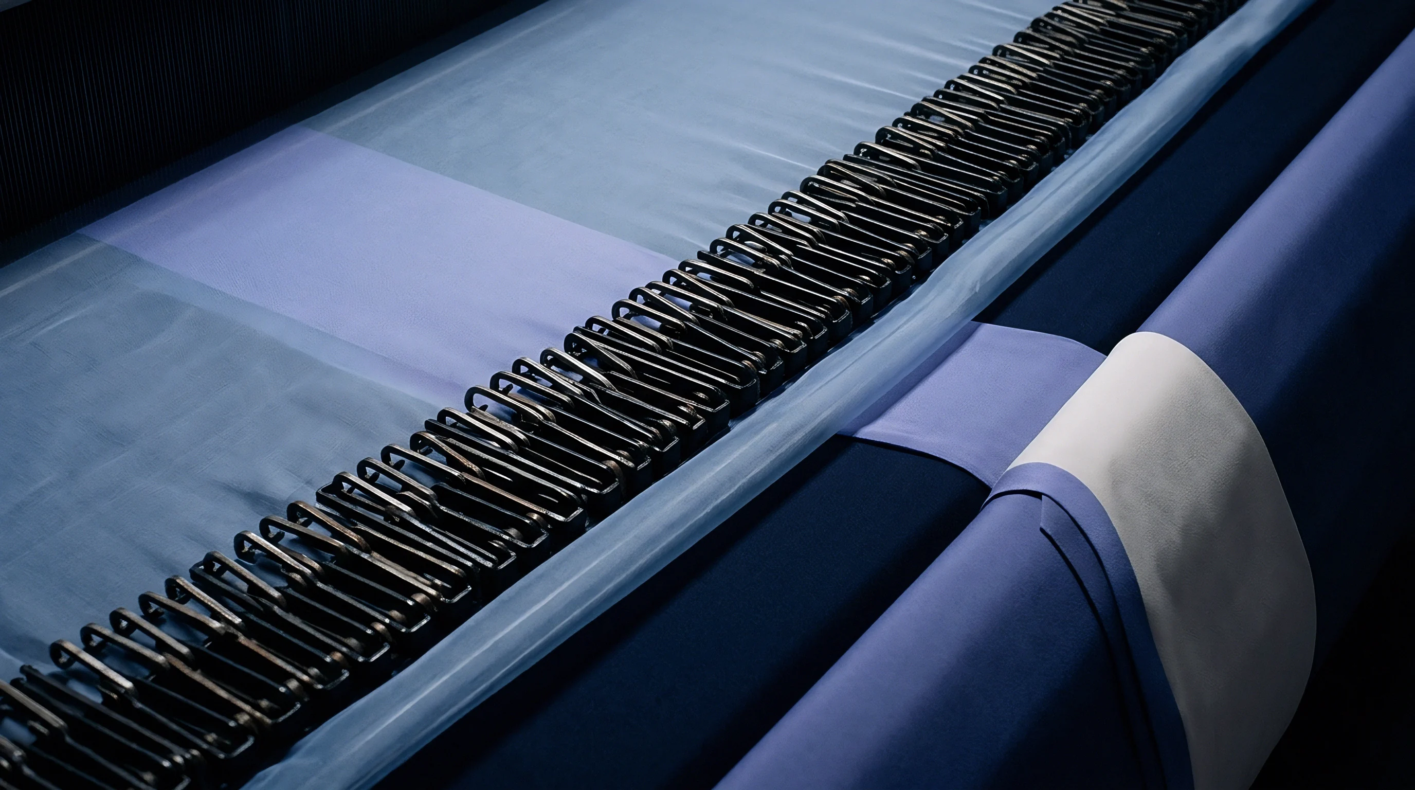
Dent
Reed density defines warp yarn distribution across the physical width of the weaving machine. The reed consists of flat stainless steel wires set at precise intervals between top and bottom ribs, with the openings between wires called dents. Reed count refers to dents per unit length ~ traditionally expressed as dents per inch or per 2 inches in legacy systems, and as dents per centimetre or per 10 centimetres under metric standards.
Selecting the right reed count and denting plan bridges warp end count to total reed width. The denting plan specifies how many warp ends pass through each reed dent opening. Standard plans deploy 1, 2, 3, or 4 ends per dent.
In specialized structural weaves or dense selvage zones, plans may specify up to 6 or 8 ends per dent to reinforce edge stability.
| Reed Count (Dents/cm) | Wire Thickness (mm) | Dent Width (mm) | Open Air Area (%) | Compatible Spun Yarn Range (Ne) | Compatible Filament Range (dtex) |
|---|---|---|---|---|---|
| 10 | 0.40 | 0.60 | 60.0 | Ne 6/1 to 16/1 | 300 to 600 dtex |
| 16 | 0.30 | 0.325 | 52.0 | Ne 16/1 to 30/1 | 150 to 300 dtex |
| 20 | 0.25 | 0.250 | 50.0 | Ne 30/1 to 50/1 | 100 to 150 dtex |
| 24 | 0.20 | 0.216 | 52.0 | Ne 40/1 to 80/1 | 75 to 100 dtex |
| 30 | 0.15 | 0.183 | 55.0 | Ne 80/1 to 120/1 | 30 to 75 dtex |
Selecting a reed count requires balancing yarn bulk against wire interference. Packing too many ends into one dent creates reed marks ~ vertical streaks where warp threads bunch together. Conversely, using a fine reed count with 1 end per dent adds wire blades across the width, increasing friction and abrading warp yarns during shed opening.
Because reed denting dictates end density, high-density warp setts require careful calculation of the reed wire thickness ratio. The open air area percentage within a reed determines how easily yarn slubs, knots, and loose filaments pass through without catching, calculated as follows:
Open Area Percentage = (Dent Width / (Dent Width + Wire Thickness)) 100
When reed wire thickness consumes over 50 percent of available pitch, yarn chafing increases, leading to end breaks, fuzz balls, and loom stoppages. Fine cottons and micro-filament synthetics require high open area percentages to preserve yarn surfaces.
Dense warp setts require finer reed wires to prevent reed marks and excessive yarn friction during shed formation.

Does Heavy Denting Distort the Weft Insertion Rate?
Heavy denting configurations, like placing 4 or 5 coarse ends per dent, distort weft insertion on high-speed air-jet looms. Packing multiple heavy warp threads into a single dent forms dense vertical yarn pillars during shed closure, obstructing the air blast from auxiliary nozzles and dropping pressure inside the reed profile channel.
Because air pressure governs filling transport speed, pressure drops across a turbulent reed channel cause the weft tip to lose velocity, leading to trailing pick folds, tip bucking, and loom stops. High-speed air-jet weaving requires finer reed counts with no more than 2 ends per dent when running continuous filament or high-twist spun yarns. Rapier machines tolerate dense denting better, as mechanical heads carry the filling without relying on pneumatic streams.
Selvage zones require dedicated reed calculations to stabilize cloth edges against lateral tension during weaving and finishing, typically spanning 6 to 12 millimetres on each side of the fabric body. Because selvages use higher thread densities or double-end denting, their space must be included directly in total reed width formulas. Omitting selvage end distribution results in undersized reed allocations or edges that curl during dyeing.

Required Parameters for Reed Specification Dossiers
- Nominal Reed Count defined precisely in dents per centimetre or dents per inch measured at standard room temperature.
- Total Reed Dent Capacity establishing the maximum usable wire width between end stanchions on the loom bed.
- Wire Thickness and Alloy Grade specifying hardened stainless steel wire dimensions to guarantee dimensional stability under peak beating force.
- Channel Depth and Profile Dimensions matching the specific weaving machine shuttle, rapier guide tape, or air-jet tunnel requirements.
- Denting Plan Array mapping the exact number of warp ends per dent across body, transition, and selvage zones.
- Usable Reed Space Allowance detailing total wire width minus mechanical clamp clearance parameters.
Incorrect reed selection alters fabric hand. Poorly chosen wire thickness distorts warp spacing, changing light reflection and texture across the finished face. Section 4.2 of the International Fabric Buyers Association Purchasing Terms specifies that reed wire thickness deviations exceeding 0.05 millimetres void supplier immunity against structural warp streak claims.


Equations
Calculating loom reed width combines structural yarn parameters, crimp mechanics, wet processing contraction factors, and selvage configurations into a single calculation workflow. The master formula derives total reed width by calculating the physical space needed for body warp ends and adding space for selvage structures.
Establishing body reed width follows this calculation sequence:
Step 1: Calculate Total Body Warp Ends
Total Body Ends = Target Finished Width Finished Ends Per Unit Width / (1 + Finishing Warp Stretch Factor)
Step 2: Calculate Required Grey Fabric Width
Grey Width = Target Finished Width / (1 – Wet Processing Contraction Percentage / 100)
Step 3: Calculate Required Reed Space for Body
Body Reed Width = Grey Width / (1 – Weft Crimp Percentage / 100)
Step 4: Calculate Reed Dents Required for Body
Body Dents = Total Body Ends / Ends Per Dent
Step 5: Calculate Total Reed Width Including Selvages
Total Reed Width = (Body Dents / Reed Count) + (2 Selvage Width in Reed)
Alternatively, when calculating directly from total warp ends and reed count, the equation maps occupied dents across the reed face:
Total Reed Width = / Reed Count
Calculated reed widths that fail to account for selvage cord draw-in produce narrow usable cut widths that trigger immediate garment panel cutting scrap penalties.
Technical trials showed a 2.8 percent discrepancy in finished width when substituting a 40-dent reed for a 20-dent double-threaded reed. This structural change altered the open air space profile, shifting weft crimp without any change to warp beam let-off tension.
| Parameter | Case A: Cotton Twill (Bottomweight) | Case B: Polyester Lining (Filament) | Case C: Worsted Wool (Suiting) |
|---|---|---|---|
| Target Finished Width | 150.0 cm | 140.0 cm | 148.0 cm |
| Target Finished Sett (Ends x Picks) | 42.0 x 24.0 ends/cm | 48.0 x 30.0 ends/cm | 28.0 x 24.0 ends/cm |
| Total Body Warp Ends | 6,300 ends | 6,720 ends | 4,144 ends |
| Wet Processing Width Contraction | 7.5 % | 9.0 % | 8.0 % |
| Calculated Grey Width | 162.16 cm | 153.85 cm | 160.87 cm |
| Weft Crimp (Contraction) Factor | 6.0 % | 3.5 % | 5.5 % |
| Calculated Body Reed Width | 172.51 cm | 159.43 cm | 170.23 cm |
| Chosen Denting Plan (Body) | 3 ends per dent | 2 ends per dent | 2 ends per dent |
| Body Dents Required | 2,100 dents | 3,360 dents | 2,072 dents |
| Calculated Reed Count | 12.17 dents/cm | 21.07 dents/cm | 12.17 dents/cm |
| Selected Standard Stock Reed | 12.0 dents/cm | 20.0 dents/cm | 12.0 dents/cm |
| Adjusted Body Reed Width | 175.00 cm | 168.00 cm | 172.67 cm |
| Selvage Width (Each Side in Reed) | 1.5 cm (36 ends @ 2/dent) | 1.0 cm (40 ends @ 4/dent) | 1.2 cm (24 ends @ 2/dent) |
| Final Total Reed Width Requirement | 178.00 cm | 170.00 cm | 175.07 cm |
| Note: Calculations assume standard atmospheric condition testing. Reed count selection rounded to nearest available commercial stainless steel reed stock. | |||
Case A illustrates a heavy combed cotton bottomweight twill. Cotton’s 7.5 percent wet-processing contraction under mercerization and jet dyeing requires a 162.16 centimetre grey width to yield 150.0 centimetres finished. Because the 3/1 twill generates 6.0 percent weft crimp during weaving, body reed width must expand to 172.51 centimetres.
Selecting a standard 12.0 dents/cm reed adjusts body reed space to 175.00 centimetres. Adding 3.0 centimetres total selvage allocation sets the final loom reed width at 178.00 centimetres.
Case B covers a lightweight polyester filament lining. Continuous filament yarns show low interlacing crimp (3.5 percent) under high air-jet warp tension, but heat setting causes 9.0 percent thermal contraction. Reaching a 140.0 centimetre finished width requires an off-loom grey width of 153.85 centimetres and a body reed width of 159.43 centimetres.
Using a standard 20.0 dents/cm reed expands body space to 168.00 centimetres, yielding a total reed width of 170.00 centimetres including selvages.
Case C models a fine worsted wool suiting. Worsted yarns show moderate relaxation contraction (8.0 percent) during crabbing and piece dyeing. Combined with a 5.5 percent weft crimp factor, initial body reed width calculates to 170.23 centimetres.
Adjusting to a standard 12.0 dents/cm reed shifts body space to 172.67 centimetres, while adding 2.4 centimetres for selvages brings total reed width to 175.07 centimetres.
Critical Technical Verification Parameters before Locking Production Math
- Yarn Linear Density Tolerances verifying that raw yarn lots do not exceed plus or minus 2.5 percent mass variation, which directly alters crimp take-up.
- Actual Wet Finishing Route Confirmation auditing whether the finishing plant will utilize open-width continuous processing or rope-form jet processing.
- Loom Warp Beam Tension Profiles measuring electronic let-off settings across shift changes to maintain consistent weft contraction rates.
- Selvage Weave Structure Matching confirming that selvage end counts and denting plans match body crimp rate to prevent tight or slack edges.
- Finish Chemical Add-On Mass accounting for weight gain from fluorocarbon or resin coatings that alter final fabric geometry and sett.
Warp crimp varies across loom width. Outer warp ends experience higher lateral friction than center ends, creating crimp gradients on broadloom widths over 190 centimetres. An unverified yarn contraction estimate once forced three hundred rolls of broadcloth below minimum garment marker width, incurring an eleven thousand dollar remanufacturing charge.

Tolerance
Loom reed width calculations provide ideal mathematical models, but production takes place within physical tolerance windows. Variations in yarn moisture regain, weave room humidity, warp beam tension, and stenter pin chain wear create dimensional fluctuations across bulk runs. Specifications that omit practical engineering tolerances frequently lead to commercial disputes between buyers, weaving mills, and dyehouses.
Cuttable width defines usable fabric, excluding selvages and pin-hole damage from stenter clips. International trade terms require delivered fabric to meet or exceed agreed cuttable width across 95 percent of shipment rolls. If a contract specifies a 148 centimetre cuttable width, reed calculations should target a nominal 150 centimetres to absorb natural processing variation.
Weave room environmental control directly impacts off-loom width stability. Cotton yarns lose elasticity and swell as relative humidity rises. When weaving shed humidity fluctuates between 55 percent and 75 percent, warp yarn diameters expand, raising weft crimp and narrowing grey fabric.
Maintaining atmospheric control within plus or minus 3 percent relative humidity ensures consistent grey width from calculated reed dimensions.
Reed wire wear over long production cycles introduces subtle density variations. Stainless steel reed wires subjected to millions of beats from coarse spun yarns undergo thinning and pitch distortion. Worn or damaged dents let warp threads spread unevenly, causing localized width variations and streak defects.
Routine maintenance requires measuring reed dent pitch uniformity every 50,000 metres of woven output.
Mill audits eliminate width calculation errors. Specifying exact reed dimensions during contract negotiation with commission weavers prevents disputes over narrow usable fabric widths. Technical audits must verify that loom reed space settings match engineering dossiers, preventing operators from using off-shelf reeds that alter finished fabric properties.
Landed fabric costs link directly to calculation accuracy. Overspecifying reed width wastes raw yarn in edge trimmings and increases energy consumption during drying. Underspecifying reed width leads to rejected fabric lots, cutting marker scrap penalties, and remanufacturing runs.
Grounding reed width calculations in empirical crimp lab data, wet-processing contraction profiles, and standardized denting plans secures control from yarn purchasing through final delivery.