Warp Cover Factor Calculation Methods for Woven Fabric Specifications
Warp cover factor calculation requires precise yarn diameter, density, and count conversions to establish enforceable fabric specifications and prevent bulk weaving defects.
Empiricism
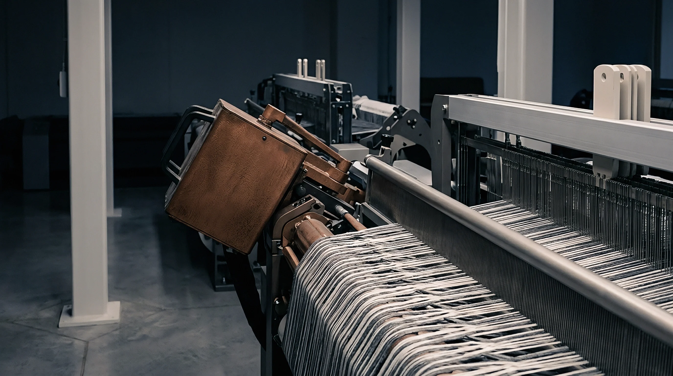
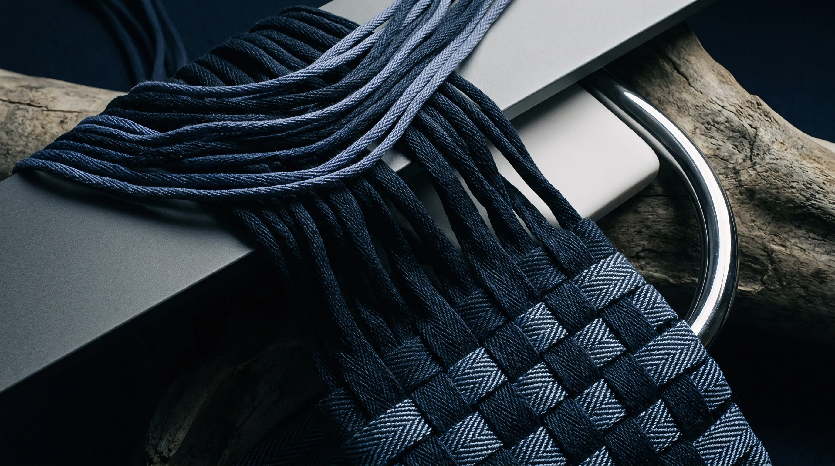
Woven fabric performance ultimately comes down to spatial geometry inside the loom shed and in the relaxed cloth. When a technical textile or commercial garment fails structurally, the issue usually stems from misjudging thread packing. Spacing, yarn diameter, and structural density dictate where a weave falls between an open mesh and an impenetrable barrier.
Quantifying that balance relies on mathematical models that condense yarn dimensions and thread counts into a single dimensionless index: the cover factor. Warp cover factor specifically measures the fraction of fabric surface area hidden by warp ends relative to total area. If this value is miscalculated during specification, buyers risk allocating loom capacity to constructions that either jam during beat-up or fall short on physical performance after finishing.
Cover factor calculations grew out of empirical models created for staple cotton spinning systems. These classic formulas treat yarn as a smooth, uniform cylinder of constant volumetric density. Under that geometric assumption, yarn diameter scales inversely with the square root of the yarn count in indirect numbering systems.
In traditional English cotton count (Ne), yarn diameter in inches equals 1 divided by 28 times the square root of the count. That constant of 28 reflects the typical packing fraction and fiber density of medium-staple cotton spun at standard ring twist multipliers. Classical warp cover factor formulas thus express the index simply as ends per inch divided by the square root of the English cotton count.

Classical Peirce Formulations and Fractional Limits
Structural analysis of woven cloth gained formal mathematical rigor through the geometric models of Frederick Thomas Peirce. The classical Peirce warp cover formula provides a practical numerical index that mill engineers have used for decades to project loom beat-up limits and fabric weight. In imperial units, the formula is:
K1 = n1 / sqrt(N1)
In this expression, K1 is the imperial warp cover factor, n1 is the warp density in ends per inch, and N1 is the indirect English cotton count (Ne). A cover factor of 28 denotes a theoretical fully closed fabric surface where parallel warp yarns rest side by side without radial deformation. Pushing an imperial cover factor past 28 requires physical yarn compression or weaves like twills and satins that accommodate higher packing limits.
International specifications often specify fractional cover factors or metric systems to keep calculations consistent across different fibers. Fractional warp cover (C1) is the actual mathematical ratio of covered surface area to total surface area, stripping out empirical constants tied to cotton. Expressed as yarn diameter divided by thread spacing, it gives a decimal value between zero and one.
When yarn diameter (d1) and warp pitch (p1) share the same units, the calculation is straightforward:
C1 = d1 / p1 = d1 x n1
For direct yarn numbering systems like Tex or Decitex, cover factor calculations convert to SI units. Metric models eliminate the inverse-square relationship used with indirect counts. The Tex warp cover equation takes ends per centimeter and the square root of the Tex count:
K_tex = (ends/cm x sqrt(Tex)) / 10
Converting between imperial Peirce numbers and Tex cover factors requires exact multipliers. Translating an imperial K1 into Tex K_tex means multiplying K1 by 0.957. Going from Tex cover factor to fractional warp cover requires fiber mass density and yarn packing coefficients.
Assuming a standard cotton packing fraction of 0.60 and a fiber density of 1.54 grams per cubic centimeter, fractional warp cover equals the imperial cover factor divided by 28, or the Tex cover factor divided by 29.25.
Calculated warp cover values based on nominal spun yarn counts understate physical space blockage by five to eight percent due to surface fiber halo.
Calculated warp cover often diverges from mill reality when technicians rely on nominal yarn counts instead of measured linear densities. Nominal counts are target figures assigned in spinning; bulk yarn numbers vary within commercial tolerances, typically plus or minus three percent. A three percent drop in actual count increases yarn diameter, raising the true cover factor above the calculated baseline.
The assumption of round yarn geometry also fails inside the fabric structure. Beat-up tension and intersecting weft threads crush round yarns into elliptical profiles. This flattening widens the effective width of each warp end while reducing its vertical thickness.
Imperial formulas ignore this cross-sectional deformation, causing errors in estimated air permeability, light transmission, and barrier performance.
Spec sheets that list warp cover values without naming the underlying equation introduce real ambiguity into procurement. An imperial Peirce cover factor of 20 corresponds to a fractional warp cover of roughly 0.71, while a Tex cover factor of 20 equals a fractional cover of 0.68. Settling on the mathematical method before issuing RFQs prevents misalignments between buyer specs and mill deliveries.
Evaluating these mathematical distinctions across technical dossiers establishes clear verification criteria before approving bulk greige production runs.
Engineers still debate whether optical light-transmission meters or 2D cross-sectional geometry gives the truer baseline for light-blocking cover calculations in fine filament weaves.

Derivation
Converting values accurately across international yarn numbering systems is essential for cover factor work. Global fabric sourcing means translating specs written in indirect counts into direct mass-per-unit-length values. A formula derived for English cotton count produces meaningless numbers if applied to Tex or Denier without adjusting for system geometry.
Translating cover factors between systems requires accounting for fiber specific gravity, yarn packing density, and unit scales. Because direct systems reverse the relationship ~ smaller numbers mean finer yarns ~ the scaling logic flips compared to traditional cotton counts.

Systemic Conversion Equations for Cover Factors
Translating indirect systems like English Cotton Count (Ne), Metric Count (Nm), or Worsted Count (Ne_w) into direct systems like Tex, Decitex (dtex), and Denier (d) relies on fixed conversion constants:
Tex = 590.541 / Ne
Tex = 1000 / Nm
Tex = 885.81 / Ne_w
Tex = Denier / 9
Substituting these count relationships into warp cover equations enables clean conversion across global specifications. Converting an imperial Peirce cover factor (K1) into fractional cover (C1) for an arbitrary yarn requires basic physical fiber parameters. Fiber mass density (rho, in g/cm³) and yarn packing factor (phi, the ratio of fiber volume to total yarn volume) govern the physical diameter of the yarn.
Expressed in centimeters using Tex, density, and packing factor, yarn diameter is:
d (cm) = sqrt( (4 x Tex) / (10^5 x pi x rho x phi) ) = 0.00357 x sqrt( Tex / (rho x phi) )
Multiplying this calculated diameter by warp end density in ends per centimeter gives the true geometric fractional warp cover. If ends are given per inch (epi), divide by 2.54 to convert to ends per centimeter before applying the diameter formula.

Fiber Mass Density and Packing Factor Variables
Ignoring fiber specific gravity introduces major errors into cover calculations. Polypropylene has a specific gravity of 0.91 g/cm³, while viscose rayon sits at 1.52 g/cm³. A 150 denier polypropylene yarn takes up considerably more physical volume ~ and has a larger diameter ~ than a 150 denier viscose yarn.
Built at the same thread density, the polypropylene cloth will have a much higher warp cover factor than the viscose structure. The table below lists the physical parameters needed for cross-material cover calculations.
| Fiber Type | Specific Gravity (g/cm³) | Nominal Packing Factor (phi) | Diameter Constant (Kd for Tex) | Equivalent Imperial Constant |
|---|---|---|---|---|
| Cotton (Combed Ring Spun) | 1.54 | 0.62 | 0.00366 | 28.00 |
| Cotton (Rotor Spun) | 1.54 | 0.55 | 0.00388 | 26.40 |
| Polyester (Continuous Filament) | 1.38 | 0.82 | 0.00336 | 30.50 |
| Polyester (Spun Staple) | 1.38 | 0.58 | 0.00399 | 25.70 |
| Nylon 6,6 (Continuous Filament) | 1.14 | 0.84 | 0.00365 | 28.10 |
| Nylon 6,6 (Textured Filament) | 1.14 | 0.50 | 0.00473 | 21.70 |
| Viscose Rayon (Continuous) | 1.52 | 0.80 | 0.00324 | 31.60 |
| Wool (Worsted Spun) | 1.31 | 0.55 | 0.00421 | 24.30 |
| Polypropylene (Filament) | 0.91 | 0.81 | 0.00416 | 24.60 |
Running a sample calculation for a synthetic technical fabric shows how much these physical constants matter. Take a high-density weave specified with a 70 Denier continuous filament Nylon 6,6 warp at 135 ends per inch. To find the fractional warp cover, first convert linear density to Tex:
Tex = 70 / 9 = 7.78 Tex
Applying the diameter formula using Nylon 6,6 properties (specific gravity 1.14, packing factor 0.84) gives absolute yarn diameter:
d (cm) = 0.00357 x sqrt( 7.78 / (1.14 x 0.84) ) = 0.00357 x sqrt( 8.13 ) = 0.01018 cm
Converting 135 ends per inch to ends per centimeter:
n1 (ends/cm) = 135 / 2.54 = 53.15 ends/cm
Multiplying physical yarn diameter by ends per centimeter gives the fractional warp cover:
C1 = 0.01018 cm x 53.15 ends/cm = 0.541 (or 54.1 percent cover)
If an engineer evaluated this Nylon fabric using the default cotton constant of 28 without adjusting for density and packing, the formula would yield 14.8 out of 28 ~ an apparent cover of 52.8 percent. That 1.3 percent discrepancy might seem minor on paper, but in high-performance applications it causes measurable differences in hydrostatic head pressure and air permeability.
Packing factors vary depending on yarn structure; modern continuous filament yarns with flat, untextured cross-sections reach packing factors near 0.85, whereas textured yarns (DTY) drop to 0.45 or lower as crimp forces push filaments apart. As bulk increases, diameter expands for the same linear density, increasing physical cover without changing yarn mass. Microscopic cross-sectional verification on filament shipments validates that texturizing crimp levels align with the specified packing density factor prior to weaving bulk orders.
Yarn density calculations for synthetic filament fabrics consistently show higher spatial cover than staple spun yarns of equivalent linear mass.

Yarn
Fiber arrangement inside spun and filament yarns introduces variables that alter thread diameter beyond ideal geometric models. Calculating warp cover from nominal counts assumes uniform mass along the yarn axis. On the weaving floor, that assumption breaks down.
Spun yarns carry twist gradients, fiber migration, surface fuzz, and radial shifts that alter their physical envelope. Filament yarns compress and deform at every pick intersection in the weave. Specifying cover factor accurately requires accounting for how these structural factors alter real warp dimensions.
Twist Factor and Radial Compression Mechanics
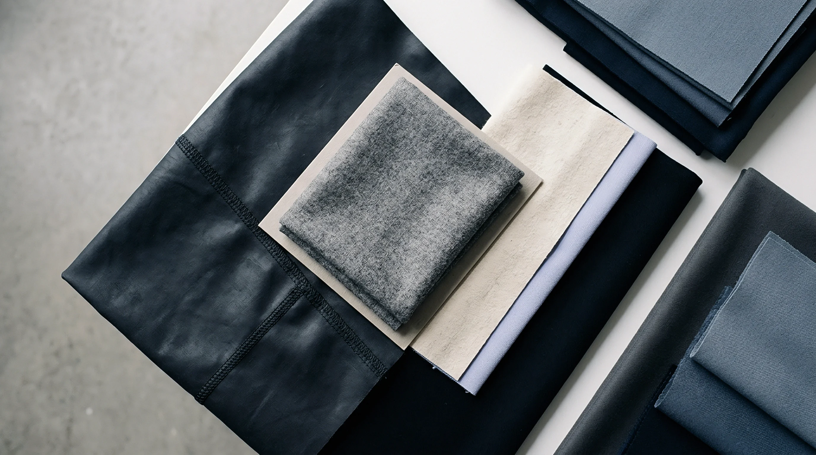
Twist directly alters yarn diameter and packing density. Twisting a staple fiber bundle forces outer fibers into helices, generating axial tension that pulls the core inward. Higher twist increases density and shrinks diameter, tightening the outer surface envelope.
Soft-twist yarns stay open, maintaining lower packing density and a larger diameter. Twist insertion is quantified by the twist multiplier (TM in imperial counts) or twist factor (alpha_tex in metric):
TM = Turns Per Inch / sqrt(Ne)
alpha_tex = Turns Per Meter x sqrt(Tex) / 100
When the twist multiplier exceeds standard levels (3.5 to 4.0 for ring-spun warp yarns), core density increases sharply. The smaller diameter reduces the area covered by each end, lowering true warp cover even though thread density and yarn count stay unchanged.
How Does Yarn Twist Alter Effective Warp Cover?
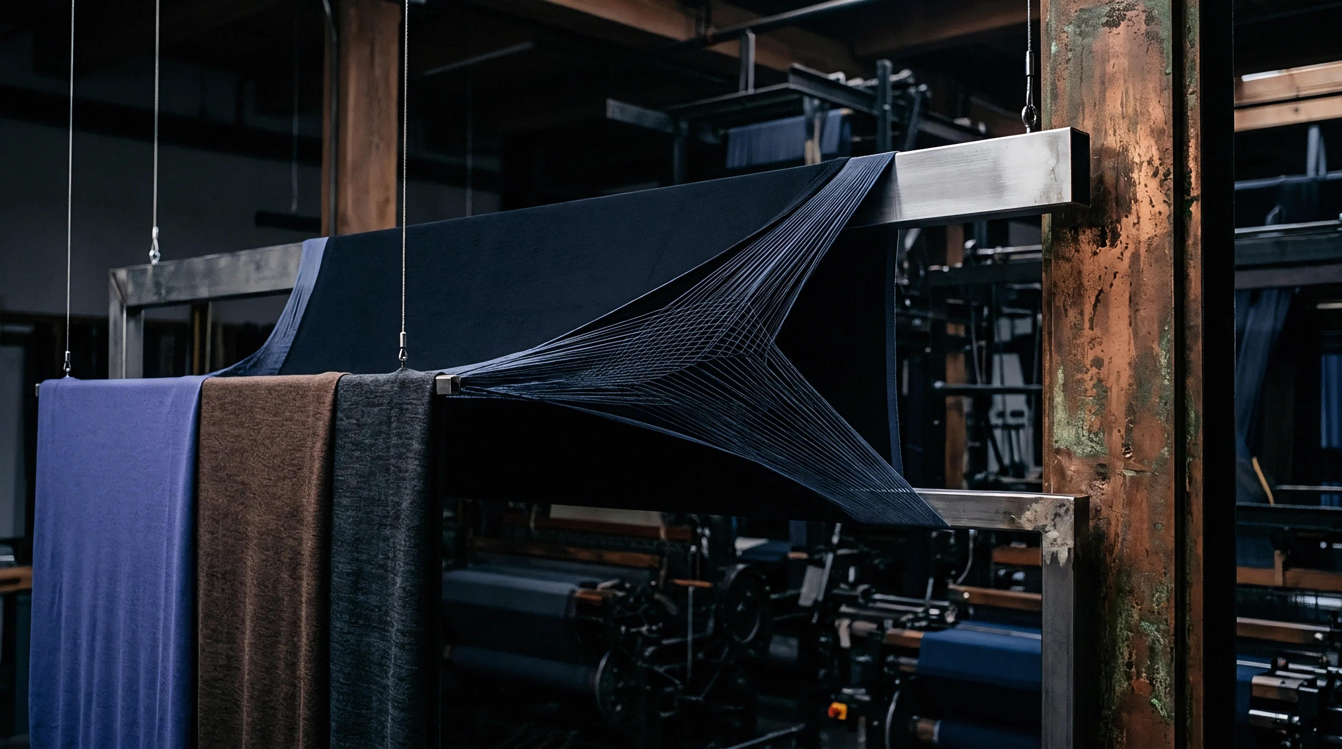
Raising the twist multiplier on a 20s Ne cotton warp from 3.2 to 4.5 reduces yarn diameter by roughly seven percent through radial compaction. In a cloth woven at 60 ends per inch, that change drops fractional warp cover from 0.480 to 0.446. The finished fabric ends up more porous and less opaque despite meeting specified end count and weight.
Sourcing contracts that omit twist multipliers leave room for spinners to supply high-twist yarns that fulfill basic construction specs while degrading cover.
Spinning system selection also changes core packing. Ring-spun yarns carry a dense core wrapped in uniform outer helices, yielding consistent packing factors around 0.62. Rotor-spun (open-end) yarns have a looser core with wrapper fibers on the surface, producing lower packing factors (0.55) and wider physical diameters.
Air-jet yarns (like Vortex) form a stiff, parallel core under tight surface wrapping, giving stable diameters that resist beat-up flattening.
Several mechanical and structural factors across yarn spinning and preparation cause deviations from calculated cover:
- Nominal Count Inflation occurs when spinning mills operate on the heavy side of count tolerances, producing yarns that are thicker than specified and artificially inflating actual fabric cover metrics.
- Unmeasured Twist Compression arises when warp yarns receive excess twist to boost weaving efficiency on high-speed air-jet looms, unintentionally shrinking yarn diameter and dropping final fabric cover.
- Cross-Sectional Flattening takes place during beat-up when low-twist yarns deform against weft threads, expanding horizontal coverage while reducing fabric thickness.
- Filament Migration and Bulking occurs in texturized filament yarns where thermal relaxation opens filament loops, dramatically increasing spatial volume and cover factor post-weaving.
- Sizing Agent Encapsulation applies film-forming polymers (such as polyvinyl alcohol or carboxymethyl cellulose) over warp threads, smoothing surface hairiness and temporarily locking yarn diameter into a compressed state until wet desizing occurs.
Surface hairiness in staple yarns produces a secondary cover effect called fiber halo. Protruding fiber tips block light and restrict airflow through yarn gaps. Optical test equipment often reads hairiness as solid yarn body, overreporting cover.
Once the fabric is singed or biopolished, that halo is removed, and optical cover drops while geometric core cover stays the same. Optical cover protocols should specify testing before or after surface clearing.
Failing to adjust cover calculations for twist-induced compaction produces fabrics that miss opacity targets, leading to costly rejections at garment assembly.

Shed
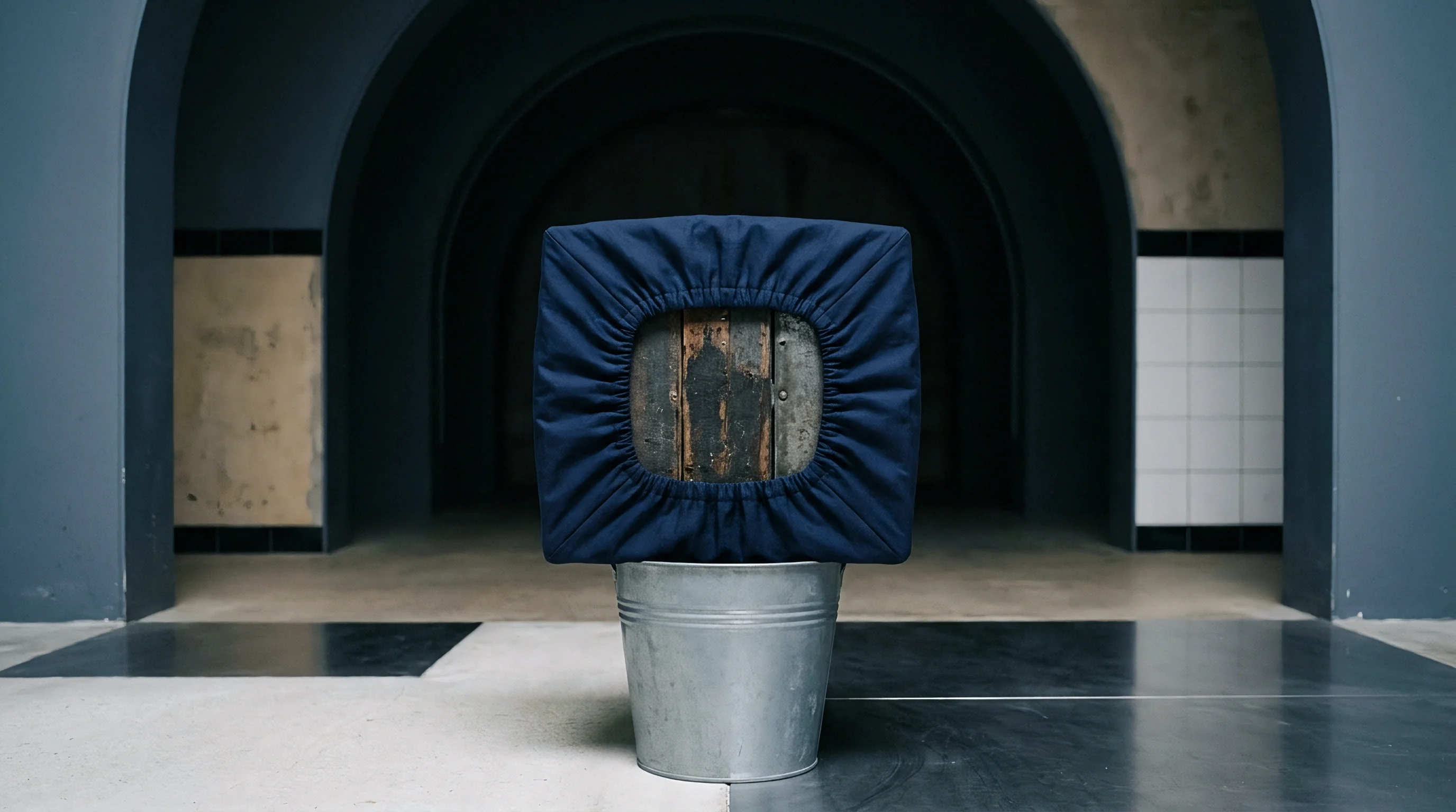
Interlacing warp and weft under tension turns static yarn dimensions into a dynamic structure. Loom setup dictates whether a fabric can actually reach its theoretical cover factor. Reed count, harness timing, warp tension, and beat-up force set physical limits on thread density.
Trying to weave dense constructions without altering loom geometry creates friction, causing end breaks, warp chafing, and visible reed marks. Evaluating cover boundaries means looking closely at mechanics at the cloth fell during beat-up.

Jamming Limits and Maximum Cover Boundary Equations
Jamming limits define the point where adjacent yarns touch and cannot pack tighter without severe structural distortion. Peirce established the basic geometric limit for plain weave jamming using rigid circular cylinders. In his model, warp fractional cover (C1) and weft cover (C2) cannot exceed specific geometric boundaries without forcing yarns out of plane along the Z-axis.
For a balanced plain weave with equal warp and weft diameters, theoretical jamming occurs when:
d x (n1 + n2) = 1
Pushing past this boundary forces extreme crimp height, maximum cross-sectional flattening, or loom stops. Ashenhurst expanded on jamming limits by creating practical max-sett formulas based on yarn diameters and weave structure. Ashenhurst’s maximum ends per inch equation is:
Max Ends/Inch = (1 / d) x (F / (F + E))
In this formula, d is yarn diameter in inches, F is threads per repeat, and E is interlacing points per repeat. For a plain weave (F=2, E=2), the maximum sett factor is 0.50 times the reciprocal of yarn diameter. A 2/2 twill (F=4, E=2) raises that factor to 0.67.
Twills and satins allow higher warp cover than plain weaves because fewer intersections per repeat lower beat-up resistance.

Warp Crimp and Loom Contraction Dynamics
Warp threads do not lie straight in cloth; bending over and under weft picks creates warp crimp. Crimp percentage (c1) measures the extra yarn length needed to form a unit length of fabric:
c1 = ((L_yarn – L_fabric) / L_fabric) x 100
Warp crimp shifts effective cover. Higher crimp increases the yarn’s angle relative to the fabric plane, slightly widening the space each end occupies. Tension differences between warp and weft during weaving also redistribute crimp dynamically.
High warp tension flattens warp crimp and increases weft crimp, pulling warp ends closer together horizontally and elevating measured cover on the loom.
Off-loom take-up concentrates thread density further. When fabric tension drops past the take-up roller, the cloth relaxes in length and width. Reed count sets on-loom end density, but off-loom relaxation increases ends per inch by three to eight percent.
As a result, off-loom greige cover factor consistently runs higher than the in-reed calculation.
| Fabric State | Warp Sett (ends/cm) | Measured Count (Tex) | Warp Crimp (%) | Calculated Tex Cover (K_tex) | Fractional Cover (C1) |
|---|---|---|---|---|---|
| On Loom (In Reed) | 24.0 | 20.0 | 1.5 | 10.73 | 0.375 |
| Off Loom (Greige Relaxed) | 25.2 | 20.4 | 7.2 | 11.38 | 0.398 |
| Scoured & Prepared | 26.0 | 20.8 | 9.1 | 11.86 | 0.415 |
| Finished (Stenter Set) | 26.5 | 21.0 | 8.5 | 12.14 | 0.425 |
| Finished (Sanforized / Compaction) | 27.8 | 21.2 | 10.8 | 12.80 | 0.448 |
| Data measured on 100% combed cotton plain weave construction under ISO 3801 standard atmospheric conditioning. | |||||
Achieving target warp cover on the floor without causing defects requires a systematic routine:
- Measure off-loom greige warp density and pick density across five distinct roll samples using ISO 3801 procedures.
- Calculate the greige fractional warp cover using the fiber specific gravity and measured yarn count.
- Determine the warp crimp percentage by dissecting ten 200 mm warp yarns under standard tension per ISO 7211-3.
- Calculate theoretical loom jamming limit to confirm whether beat-up resistance will cause reed marks or warp end breakage during weaving.
- Adjust the reed width and loom tension settings until the calculated greige cover factor sits at least four percent below the theoretical maximum.
Contractual compliance under ISO 3801 mandates mass per unit area measurements after standard atmosphere conditioning, preventing wet-tenter width stretches from artificially inflating finished warp cover metrics.
Because greige metrics can be misleading, weavers facing high beat-up resistance often back off warp tension or adjust shed timing to keep looms running. That prevents knock-offs, but it alters crimp distribution, leaving bands of uneven cover across the roll width.
Relying on post-loom shrinkage to compensate for low reed density pushes structural cover risk entirely onto the dyehouse.


Shrinkage
Wet finishing changes fabric dimensions, moving finished warp cover away from greige baseline numbers. Washing, heat, tensionless scouring, and chemical baths release stresses locked into yarns during spinning and weaving. As strain dissipates, fibers relax, yarns swell radially, and the fabric contracts along both axes.
Finished warp cover factor is therefore the net result of the entire finishing route, not just loom settings. Specifiers must account for finishing relaxation so finished goods hit density targets.
Wet Processing Relaxation and Fiber Swelling Mechanics
Putting cotton, viscose, or wool greige into aqueous baths triggers relaxation shrinkage. Yarns shorten and swell radially as internal stresses release. In cellulosics, water penetrates amorphous regions and disrupts hydrogen bonds, driving lateral swelling.
Cotton fibers swell radially by up to 14 percent in water. Mercerization amplifies this, swelling cotton fibers over 20 percent and turning flat, kidney-shaped cross-sections into rounded cylinders. This swelling permanently expands yarn diameter, increasing fractional warp cover.
Width shrinkage during wet processing concentrates warp ends. As weft threads contract in washing or dyeing, adjacent warp ends pull closer together, raising ends per inch. A five percent width contraction during scouring increases warp end density by 5.26 percent.
Assuming yarn count stays constant, warp cover rises in direct proportion to end density.

Stenter Overfeed and Finishing Tension Controls
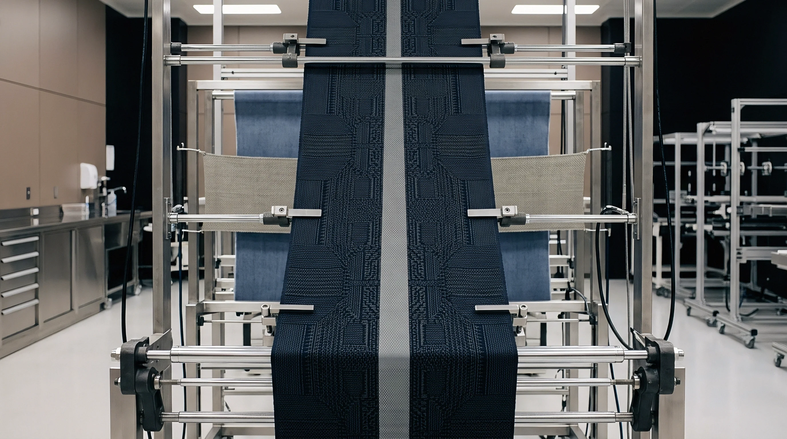
Finishing plants manipulate final cover factor using mechanical tension on stenter frames and compactors. Stenter chains grip selvedges to pull cloth through drying chambers. Applying widthwise tension pulls warp ends apart, lowering warp density.
Stretching cloth two centimeters beyond its relaxed greige width drops finished cover factor, increasing air permeability and reducing fabric weight.
Applying warp overfeed on the stenter has the opposite effect. Running the feed roller faster than the exit chain introduces extra length, letting warp threads crimp fully and pushing warp ends together. Compacting processes like Sanforizing use rubber belts under tension to press warp yarns longitudinally, maximizing finished end count and stabilizing cover against home washing.
Auditing wet finishing lines requires checking several critical controls:
- Relaxation Shrinkage Baseline establishes the minimum fabric dimensions attainable when greige stress is fully released without mechanical tension.
- Caustic Mercerization Swelling measures lateral yarn diameter expansion following sodium hydroxide treatment to verify fiber conversion efficiency.
- Stenter Overfeed Calibration monitors the ratio between feed-in roll speed and exit chain speed to prevent artificial warp stretching during drying.
- Heat Setting Dimensions locks synthetic filament fabric density on stenter frames by heat-setting thermoplastic polymers at controlled target widths.
- Calender Pressure Compaction applies high mechanical tonnage and heat to flatten warp threads vertically, boosting horizontal cover factor without altering yarn mass.
Wet processing shrinkage increases warp thread density while reducing yarn length, effectively elevating finished cover factor at the expense of linear fabric yield.
Calendering alters cover by mechanical flattening. Heavy heated rolls under high nip pressure crush round yarns into flat ribbons. This expands horizontal width while thinning vertical profile.
Fractional cover jumps after calendering, reducing air and fluid permeability. However, calendered cover is partly reversible: washing or steam causes yarns to regain roundness, dropping cover back toward pre-calender levels. Buyers specifying high cover for down-proof shells should verify whether targets rely on true thread density or temporary calender flattening.
Writing ISO 6330 dimensional stability limits directly into finishing purchase orders binds the mill to a minimum cover threshold regardless of greige width variations.


Tolerance
Verifying cover factor compliance on bulk shipments takes standardized inspection protocols. Quoting target cover factors without specifying test methods, sample conditioning, and acceptance limits invites disputes. Physical end counts, mass density checks, and digital image analysis form the pillars of cover verification.
Setting practical commercial tolerances protects functional performance without forcing impossible precision on the weaving mill.

Standardized Inspection and Optical Measurement Methods
Physical cover verification begins with measuring warp end density per unit length under ISO 7211-2 or ASTM D3775. Samples must condition at 20°C and 65% relative humidity (ISO 139) for 24 hours before counting. Unwinding rolls under tension stretches cloth lengthwise, artificially lowering end counts; measurements must come from fully relaxed samples laid flat on a non-glare surface.
Modern labs supplement pick glasses with digital image analysis. Optical cover tools use high-resolution cameras and light tables to capture fabric apertures, calculating open area versus thread area automatically. Image analysis picks up fuzz, flattening, and weave distortions that manual counts miss.
However, optical cover does not align perfectly with geometric cover formulas; light leaking through loose fiber bundles yields lower optical cover values than diameter math predicts. Specs must state whether compliance is governed by ISO 7211-2 physical counts or optical transmission.

Commercial Scenario on High-Density Down-Proof Fabrics
A commercial example illustrates the stakes of cover factor compliance. Consider an order for 50,000 meters of 40-Denier down-proof nylon taffeta for outerwear. The spec mandates a finished warp cover factor of 0.620 (via direct dtex/density formulas), equal to 172 ends per inch with a ±2.0 percent tolerance (168.5 to 175.5 ends per inch).
Air permeability cannot exceed 1.2 cm³/cm²/s under ISO 9237 at 100 Pa pressure.
On arrival inspection, the buyer’s lab recorded an average warp count of 163 ends per inch ~ a cover factor of 0.588. Although higher pick density kept fabric weight (g/m²) within contract specs, it failed to compensate for the missing warp ends. An air permeability audit on the non-compliant goods revealed average air transmission of 3.8 cm³/cm²/s.
The 5.1 percent drop in warp cover increased air leakage by over 200 percent, destroying down retention. Down feathers would leak through yarn gaps in finished jackets.
Rejecting the lot triggered a root-cause audit. The weaving mill had narrowed reed width from 170 cm to 166 cm to improve loom running efficiency, dropping greige warp density by 5 ends per inch while keeping nominal yarn count. To pass inspection, the mill used heavy friction calendering to flatten the sparse ends.
When the fabric faced heat during garment fusing, that flattening relaxed, exposing the low warp cover. The buyer rejected the 50,000-meter lot based on contract clauses tying cover tolerances directly to ISO 9237 air permeability performance.
A three percent drop in warp cover factor on 40-denier down-proof nylon increases air permeability from 0.8 to 3.2 cubic centimeters per square centimeter per second under ISO 9237 test conditions.
Commercial specs require clear numeric tolerances. Standard practice sets a ±2.5 percent tolerance on warp end density and ±3.0 percent on calculated warp cover factor. Tightening tolerances below 2.0 percent drives up mill reject rates and fabric cost, while loosening them past 5.0 percent risks failures in breathability, tear strength, seam slippage, or barrier performance.
Purchase contracts must explicitly define the formula variant, fiber specific gravity values, packing factors, conditioning standard, and test method used for verification. Spelling out these terms turns cover factor into an enforceable production requirement. Mandating that mill contracts specify greige reed density alongside finished cover targets eliminates mill adjustments that compromise fabric structure.
When bulk testing reveals a warp cover deficit on delivered goods, the buyer applies financial debit notes proportional to lost yield or rejects non-compliant rolls outright before cutting operations begin.