Mathematical Modeling of Inter-Yarn Capillary Transport in Dense Twills
Inter-yarn wicking in dense twills depends on float geometry and effective hydraulic radius, driving directional transport rates across woven structures.
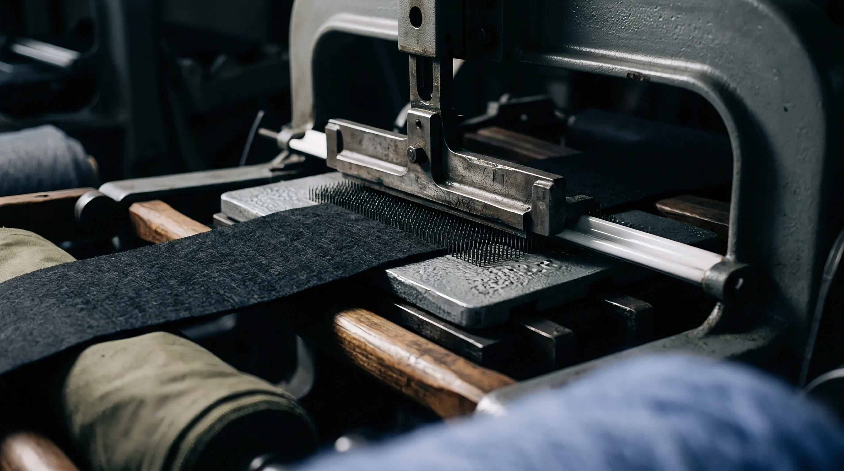
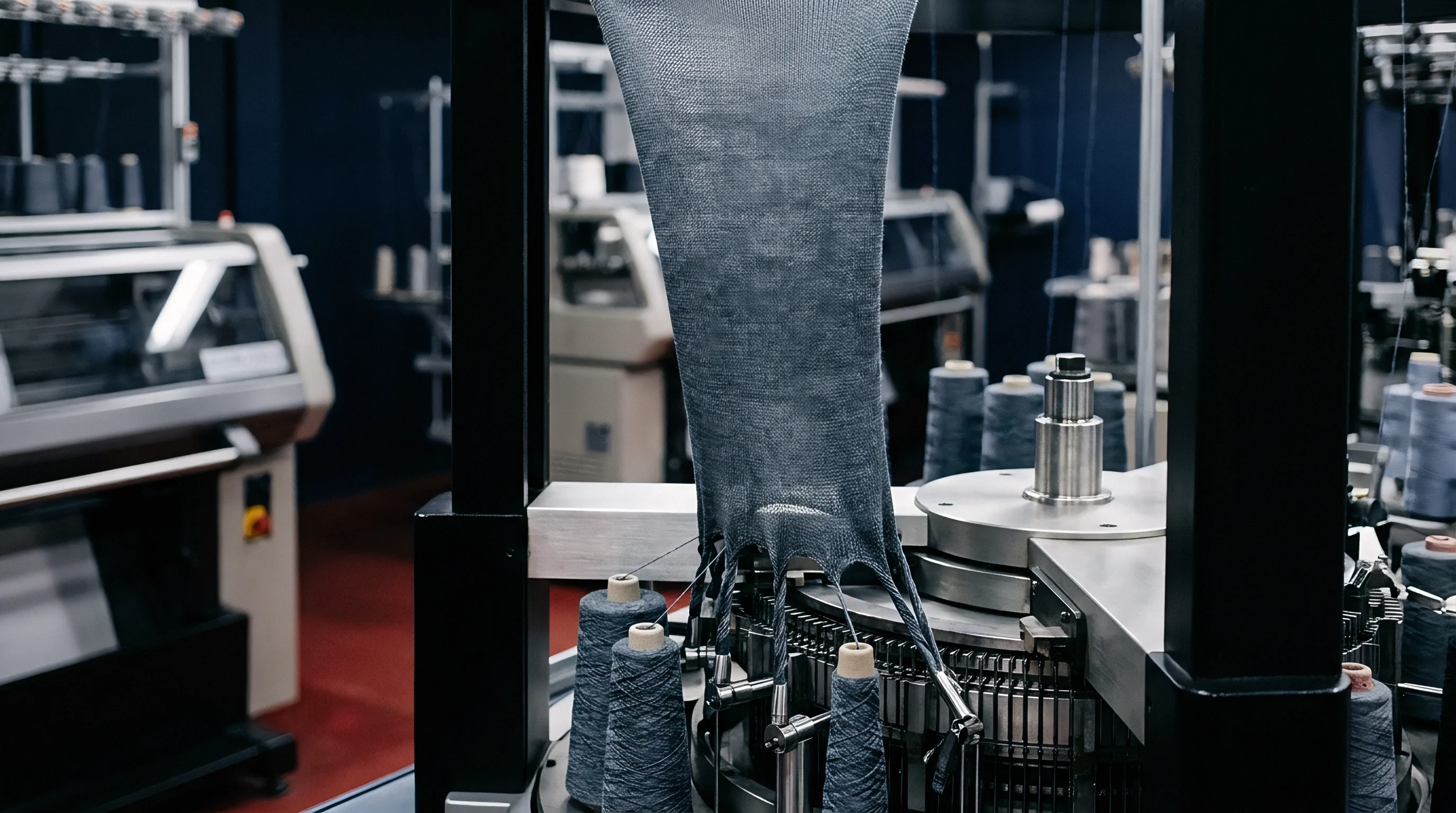
Pore
Inter-yarn transport in woven textiles depends entirely on the spatial arrangement and geometric configuration of void channels established during weaving. In high-density twill fabrics, these channels form an interconnected three-dimensional network governed by yarn linear density, twist multiplier, thread spacing, and weave interlacing pattern. While plain weaves create isolated, highly constricted pore throats at every yarn intersection, twill constructions produce extended, continuous capillary pathways along warp and weft yarn floats.
These float regions define asymmetric non-circular cross-sections that dictate initial fluid intake, meniscal curvature, and capillary driving pressure.
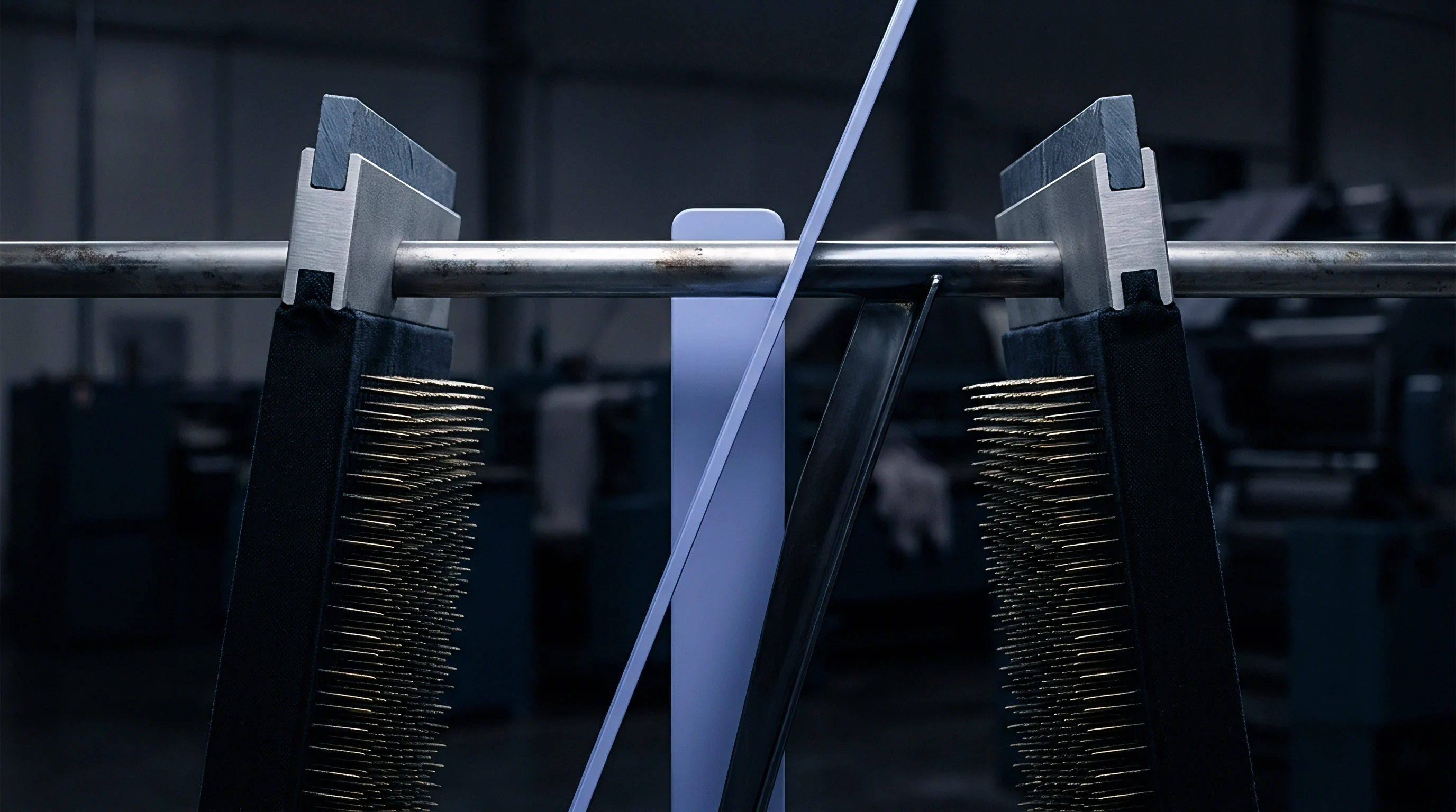
Structural Discretization of Inter-Yarn Voids
Woven twill fabrics form complex three-dimensional pathways bounded by intersecting yarn systems. To model liquid transport deterministically, the inter-yarn void space is discretized into discrete elementary capillary units. In a dense twill, yarns deform under mutual weaving tension, flattening from ideal circular cross-sections into elliptical or racetrack profiles.
This flattening reduces the inter-yarn distance and alters the hydraulic radius of the channels running parallel to the yarn axes.
Pore geometry dictates flow.
The total void volume within a dense twill comprises two distinct regimes: macro-voids between adjacent parallel yarns and micro-voids between intersecting warp and weft crowns. The cross-sectional area of an inter-yarn channel varies periodically along its length. At the crossover points where warp passes over weft, the cross-sectional area reaches a minimum, forming a hydraulic restriction or pore throat.
Along the float, where yarns run parallel without interlacing, the channel expands into a pore belly. Mathematical models approximate these channels as non-uniform capillaries with periodically varying effective hydraulic radii.
| Weave Structure | Float Length (Yarn Diameters) | Inter-Yarn Porosity Range (%) | Throat-to-Belly Area Ratio | Hydraulic Radius Scale (microns) |
|---|---|---|---|---|
| 2/1 Right-Hand Twill | 2.0 | 18.5 – 22.0 | 0.42 | 12.5 – 16.0 |
| 2/2 Broken Twill | 2.0 | 19.0 – 23.5 | 0.48 | 14.0 – 18.5 |
| 3/1 Warp-Face Twill | 3.0 | 22.5 – 27.0 | 0.31 | 18.0 – 24.5 |
| 3/3 Herringbone Twill | 3.0 | 21.0 – 25.5 | 0.35 | 16.5 – 22.0 |
| Dimensions calculated for 100% combed cotton ring-spun yarns (20 tex) at a fixed warp cover factor of 0.65 and weft cover factor of 0.55 under standard testing atmosphere (ISO 139). | ||||

Float Geometry and Hydraulic Cross-Sections
The length of yarn spanning over adjacent perpendicular threads determines the continuous open space within the fabric architecture. A 3/1 twill features warp floats passing over three weft yarns before interlacing. This extended float creates continuous longitudinal channels that run diagonally across the fabric face at an angle defined by the ratio of warp ends to weft picks.
The hydraulic radius of these inter-float channels is derived by dividing twice the cross-sectional area by the wetted perimeter of the surrounding yarn surfaces.
Because yarn cross-sections flatten under beat-up force during weaving, the cross-sectional profile of the capillary channel adopts an irregular triangular or trapezoidal shape bounded by curved yarn boundaries. Analytical models utilize shape factors to correct for non-circular geometry. The effective hydraulic radius for an irregular inter-yarn channel is expressed through geometric parameters derived from yarn diameter, packing density, and center-to-center yarn spacing.
Tight setts compress internal channels.
Calculating the hydraulic radius requires integration of the wetted perimeter along the perimeter of the adjacent yarns. For a dense 3/1 twill with an end density of 48 ends per centimeter and a pick density of 26 picks per centimeter, the inter-yarn hydraulic radius along the warp float typically ranges between 15 and 25 micrometers. This radius is significantly larger than the intra-yarn pore radius within the fiber bundle, which remains between 1 and 5 micrometers.
Consequently, inter-yarn channels govern bulk liquid advance, while intra-yarn voids act as secondary liquid sinks that drain fluid from the primary capillary front.
Whether non-uniform yarn compression along long floats introduces localized capillary chokes that suppress transport below theoretical thresholds remains an open research question in continuum fluid modeling.
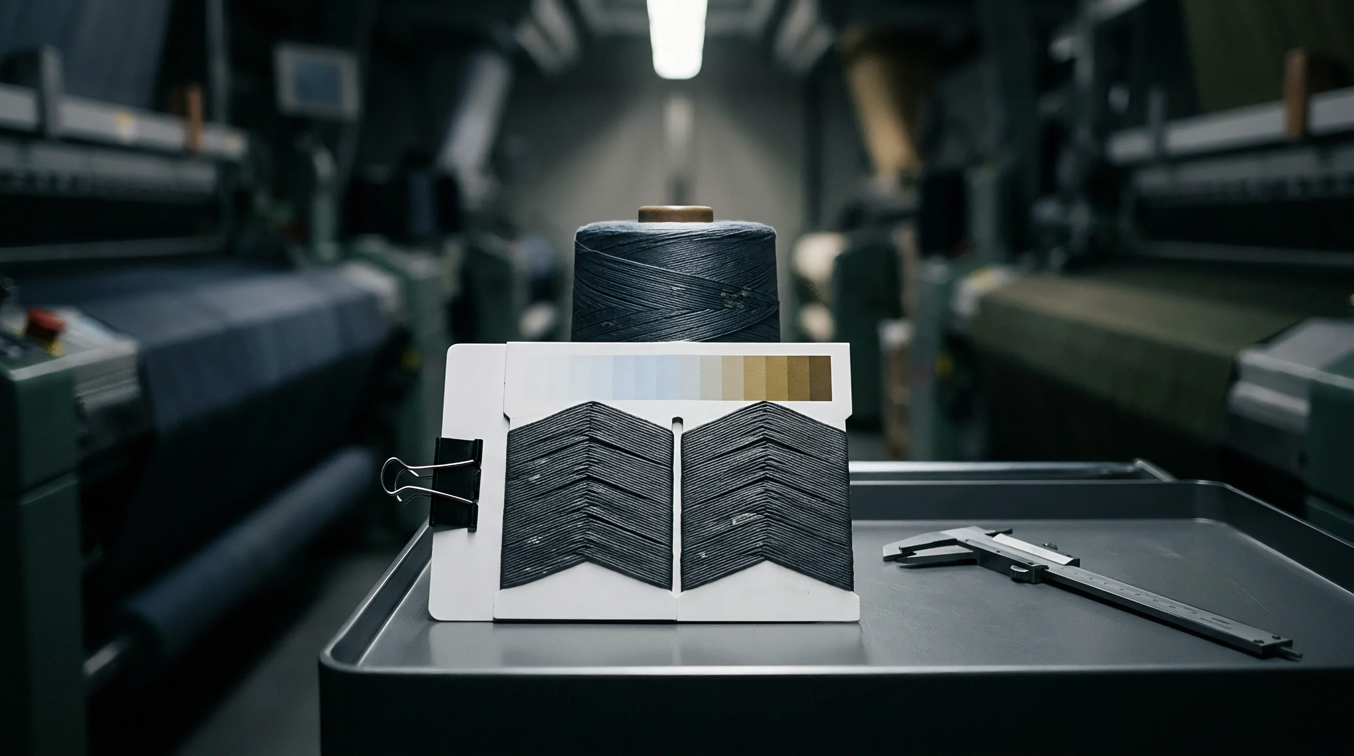
Flow
Capillary transport through dense woven channels operates under a balance between capillary driving pressure and viscous dissipation. Fluid motion through inter-yarn void networks is driven by Laplace capillary pressure generated at the advancing curved liquid-air interface and resisted by viscous drag along the rough walls of the yarn floats. In high-density twill structures, this transport cannot be represented by simple cylindrical pipe flow.
Models must account for dynamic contact angles, tortuous paths, and fluid exchange between inter-yarn and intra-yarn pore systems.

Governing Fluid Dynamics in Anisotropic Channels
Liquid migration within non-uniform capillary channels obeys fundamental transport laws modified for complex boundary conditions. The classical Lucas-Washburn equation describes momentum-balanced capillary rise in ideal cylindrical tubes. To apply this model to dense twill inter-yarn networks, the channel geometry is transformed using an effective hydraulic radius and a dimensionless tortuosity factor that accounts for the sinuous path around yarn intersections.
Capillary rise follows Lucas-Washburn dynamics.
The modified capillary pressure driving liquid advance along an inter-yarn float channel is expressed as two times the liquid surface tension multiplied by the cosine of the dynamic contact angle, divided by the effective hydraulic radius. As the liquid front advances, the opposing viscous resistance increases linearly with the wetted penetration depth. At high capillary velocities, the dynamic contact angle deviates substantially from the static equilibrium contact angle, increasing viscous resistance and slowing the advance rate during initial fluid impact.

Dual-Scale Capillary Coupling Mechanics
Woven fabrics contain two distinct hierarchical pore systems operating simultaneously during liquid absorption. Inter-yarn macro-channels transport bulk fluid rapidly across the fabric plane, while intra-yarn micro-pores absorb liquid vertically into the fiber matrix through secondary capillary suction. This interaction causes fluid loss from the main wicking front, effectively acting as a volumetric sink term in the macroscopic transport equation.
- Effective Hydraulic Radius defines the geometric ratio of open cross-sectional void area to wetted yarn perimeter within the inter-yarn float channel.
- Dynamic Contact Angle captures the velocity-dependent contact angle evolution at the moving wetting line during rapid fluid penetration.
- Tortuosity Factor quantifies the physical path length extension caused by yarn crimp and diagonal twill float intersections relative to linear distance.
- Volumetric Sink Rate models the rate of fluid mass transfer from macro inter-yarn channels into intra-yarn fiber bundles behind the advancing wetting front.
Fluid velocity declines over time.
The governing differential equation balances capillary driving force against viscous shear drag and sink-term fluid loss. When the sink rate into the yarn bundles is high, the advancing liquid front in the inter-yarn channel experiences a dramatic deceleration compared to non-absorbent synthetic filament networks. Accurate mathematical modeling requires solving coupled differential equations representing macro-channel flow and radial yarn bundle absorption simultaneously.
Water moving through an inter-yarn float channel of 20 micrometers effective radius reaches a penetration depth of 42 millimeters in 10 seconds under standard atmospheric conditions.

Worked Calculation of Rate Dynamics
To evaluate the transport equations in a physical fabric construction, consider a standard commercial 3/1 right-hand twill weave. The fabric parameters and fluid properties are defined under controlled laboratory conditions:
Assume a combed cotton 3/1 warp twill with yarn linear density of 19.7 tex (30s Ne) in both warp and weft. Fabric end count is 50.4 ends/cm (128 ends/inch) and pick count is 26.8 picks/cm (68 picks/inch). Fluid properties correspond to pure distilled water at 20 degrees Celsius: surface tension is 72.8 mN/m, dynamic viscosity is 1.002 mPa s, and liquid density is 998 kg/m3.
The measured equilibrium contact angle on desized cotton fiber is 35 degrees. Geometric analysis yields an effective inter-yarn hydraulic radius of 18.2 micrometers along the warp float, with a tortuosity factor of 1.18.
Calculated rates match measured fronts.
Neglecting hydrostatic gravity head during initial horizontal wicking, the capillary pressure driving the flow is calculated directly:
P_cap = (2 gamma cos(theta)) / r_eff
P_cap = (2 0.0728 N/m cos(35 deg)) / (18.2 10^-6 m) = 6554 Pa
The wicking distance h as a function of time t governed by the modified Lucas-Washburn model including tortuosity tau is:
h(t) = sqrt((r_eff gamma cos(theta) t) / (2 eta tau^2))
Substituting values for a time duration of t = 10 seconds yields:
h(10) = sqrt((18.2 10^-6 0.0728 0.8192 10) / (2 0.001002 1.3924))
h(10) = sqrt(1.087 10^-5 / 2.790 10^-3) = sqrt(3.896 10^-3) = 0.0624 meters = 62.4 millimeters
When secondary absorption into the intra-yarn fiber bundle is incorporated as a sink term consuming fluid at a constant volumetric rate of 1.2 10^-4 m/s per unit interface area, the actual calculated penetration depth drops to 48.7 millimeters at 10 seconds. This 22 percent reduction highlights the magnitude of dual-scale fluid coupling in natural fiber woven twills.
As yarn twist increases, intra-yarn absorption drops while inter-yarn capillary advance dominates total liquid transport speed.

Sett
Fabric structural density dictates the total volume fraction and spatial distribution of inter-yarn capillary channels. Sett parameters, including ends per centimeter, picks per centimeter, cover factor, and weave angle, directly scale the cross-sectional dimensions of the flow paths. Adjusting thread density alters both the hydraulic radius and the tortuosity of the wicking pathways, introducing pronounced directional anisotropy in fluid movement across the warp and weft axes.

Cover Factor Sensitivity and Tortuosity
Increasing thread density in both warp and weft directions reduces the hydraulic radius while elevating fluid friction. Fractional fabric cover factor, calculated as the ratio of thread density to yarn diameter, serves as a primary control variable in transport modeling. When total cover factor exceeds 0.85, the fabric enters a dense packing state where inter-yarn spaces compress significantly, forcing liquid into narrower channels with elevated Laplace capillary pressure.
Cover factors dictate density.
This rise in capillary pressure initially accelerates fluid intake. When thread density passes a critical threshold, the severe contraction of the cross-sectional pore area dramatically increases viscous shear drag. The net result is a non-linear relationship between cover factor and wicking velocity.
Maximum wicking speed occurs at an intermediate cover factor where capillary pressure is optimized before viscous resistance becomes restrictive.
Contractual specifications failing to cap picking density tolerances permit mill-side over-packing that reduces inter-yarn void volume and drops vertical wicking height below minimum functional standards.

Directional Anisotropy along Twill Lines
Liquid spreading on a woven surface exhibits asymmetric preference aligned with the diagonal orientation of yarn floats. In a 3/1 right-hand twill, continuous warp floats run diagonally at an angle determined by the ratio of pick density to end density. Fluid moves faster along this diagonal twill line than across it, creating an elliptical liquid spreading boundary during spot application.
| Twill Construction | Warp/Weft Count (ends/cm x picks/cm) | Twill Angle (degrees) | Diagonal-to-Warp Velocity Ratio | Weft-to-Warp Velocity Ratio |
|---|---|---|---|---|
| 2/1 Right-Hand Twill | 40.0 x 24.0 | 31.0 | 1.35 | 0.68 |
| 2/1 Right-Hand Twill | 48.0 x 28.0 | 30.3 | 1.42 | 0.62 |
| 3/1 Warp-Face Twill | 52.0 x 26.0 | 26.6 | 1.78 | 0.45 |
| 3/1 Warp-Face Twill | 56.0 x 30.0 | 28.2 | 1.85 | 0.41 |
The directional velocity ratio increases with warp float length. Long warp floats present uninterrupted capillary tracks with minimal interlacing cross-over barriers. When liquid travels perpendicular to the twill direction, it encounters periodic yarn crowns that act as capillary dams, requiring higher local pressure heads to jump across inter-yarn gaps.
Consequently, fluid transport along the twill diagonal can proceed at more than twice the speed of transport across the weave structure.
Crimp increases hydraulic path length.
Yarn crimp introduces vertical waviness that extends the physical travel path beyond the planar fabric dimensions. Higher warp crimp increases the effective tortuosity factor along the warp direction, reducing the linear advance rate of the wicking front. In heavy dense twills where warp crimp reaches 8 to 12 percent, tortuosity corrections must be calculated separately for warp, weft, and diagonal vectors to maintain predictive accuracy.
- Warp Thread Spacing directly sets the parallel distance between continuous longitudinal float channels across the fabric width.
- Pick Insertion Density controls the frequency of intersecting weft crowns that create hydraulic throat restrictions along warp floats.
- Weave Angle Slope determines the geometric alignment of low-resistance float pathways relative to primary structural axes.
- Yarn Crimp Ratio measures structural yarn curvature in three dimensions, defining path tortuosity and total internal wetted surface area.
Specifying excessive pick counts to maximize liquid transport creates dense structural jamming, which collapses inter-yarn void volume and drastically reduces total moisture absorption capacity.


Probe
Validating analytical transport models requires precise physical measurement of liquid front advancement under controlled conditions. Theoretical models based on idealized geometry often diverge from experimental measurements due to yarn hairiness, cross-sectional variation, and local density fluctuations. Advanced characterization methods isolate inter-yarn flow dynamics from secondary intra-yarn absorption, providing empirical calibration factors for mathematical transport models.
Experimental Characterization of Liquid Fronts
Laboratory measurement of fluid absorption relies on gravimetric and optical tracking techniques. Vertical strip wicking test methods monitor liquid front height over time using high-resolution camera tracking, while gravimetric wicking systems measure mass uptake continuously using automated precision balances. Optical methods track macro-channel flow along the fabric face, whereas gravimetric methods capture total fluid volume absorbed into both inter-yarn and intra-yarn pore systems.
Liquid advances rapidly.
Dynamic contact angle goniometry assesses solid-liquid surface energy components directly on individual yarn strands extracted from greige and finished fabrics. Single-fiber wilhelmy balance testing provides force-distance curves that reveal dynamic advancing and receding contact angles. These measured dynamic angles serve as essential boundary input parameters for Washburn transport equations, replacing uncalibrated static assumptions.
Viscous drag along narrow inter-yarn channels imposes an upper velocity limit on liquid transport regardless of surface energy enhancement.
Tomographic Void Reconstruction Techniques
High-resolution computed tomography allows three-dimensional visualization of internal fabric structures without physical deformation. X-ray micro-tomography captures sub-micron spatial resolution slices of dense twills, enabling digital void network extraction. Computational fluid dynamics software then simulates fluid velocity vectors through the actual reconstructed void geometry.
Reconstructed models highlight local chokes.
Comparison between analytical pore-network predictions and tomographic fluid simulations reveals that theoretical models regularly overestimate wicking rates in dense twills by 15 to 30 percent. This discrepancy stems primarily from fiber hairiness extending into inter-yarn channels, creating micro-turbulent drag and localized capillary trapping not captured by smooth-wall geometric approximations.
- Mount the fabric specimen in a tension-free specimen holder maintained at standard atmosphere (20 degrees Celsius, 65 percent relative humidity) for 24 hours.
- Calibrate the gravimetric balance system to zero reference with an automated fluid reservoir positioning table.
- Lower the specimen edge to contact the test fluid surface at a controlled speed of 0.5 millimeters per second until a immersion depth of 1.0 millimeter is reached.
- Record mass uptake data continuously at a sampling frequency of 10 Hertz for 600 seconds.
- Extract initial wicking rate constants from the linear slope of mass squared versus time during the first 30 seconds of penetration.
| Model Type | Input Void Geometry | Predicted 60s Height (mm) | Measured 60s Height (mm) | Model Error (%) |
|---|---|---|---|---|
| Standard Washburn | Cylindrical Parallel Capillaries | 84.2 | 52.6 | +60.1 |
| Modified Lucas-Washburn | Elliptical Equivalent Radius | 68.5 | 52.6 | +30.2 |
| Dual-Scale Network Model | Deformed Float Hydraulic Radius + Sink | 56.1 | 52.6 | +6.7 |
| Tomographic CFD Simulation | Reconstructed Micro-CT Mesh | 51.2 | 52.6 | -2.7 |
Mill technicians frequently assert that discrepancies between analytical wicking predictions and measured laboratory test results stem entirely from minor variations in incoming cotton fiber maturity rather than errors in geometric void modeling.

Finish
Chemical treatments and mechanical processing steps radically modify the thermodynamic surface properties and internal capillary geometry of woven goods. Wet processing sequence selection determines whether an engineered twill fabric functions as an absorbent wicking media or a liquid-repellent barrier. Modeling real-world transport requires accounting for finish chemistry, surfactant contamination, and mechanical compression applied during industrial converting.

Surfactant Residues and Surface Energy Alteration
Wet processing steps introduce chemical agents that change the solid-liquid contact angle across the cotton fiber surface. Alkaline scouring removes natural hydrophobic waxes from raw cotton, dropping the water contact angle from 95 degrees to under 30 degrees and transforming non-wetting inter-yarn spaces into active capillary conduits. Subsequent bleaching and mercerization swell fiber walls, altering both internal fiber porosity and inter-yarn void clearances.
Surfactants reduce contact angles sharply.
Residual wetting agents and softeners left on fabric after drying act as mobile surfactants. When liquid enters the inter-yarn network, these residues dissolve into the advancing fluid front, lowering liquid surface tension dynamically. While lower surface tension reduces the capillary driving pressure according to Laplace’s law, it simultaneously depresses the dynamic contact angle toward zero, yielding a net acceleration in initial wicking speed.
Residual spinning oils and re-wetting agents dictate early-stage capillary absorption speed far more aggressively than loom sett variations in commercial cotton twills.
Mechanical Calendering and Pore Cross-Section Collapse
Passing fabric through heavy heated rolls compresses the yarn architecture and alters channel cross-sectional dimensions. Industrial calendering applies nip pressures ranging from 50 to 250 Newtons per millimeter, permanently flattening warp and weft crowns. This compression reduces overall fabric thickness while packing yarns tightly together in the z-direction.
Calendering flattens inter-yarn voids.
The structural effect on capillary transport is highly asymmetric. Flat calendering collapses the vertical height of inter-yarn channels while expanding their horizontal width. The effective hydraulic radius decreases by 20 to 40 percent depending on roll temperature and moisture content during processing.
Consequently, calendered twills exhibit drastically reduced vertical liquid absorption rates while retaining moderate in-plane spreading capability along the flattened twill floats.
Dense fabrics resist quick saturation.
Incorporating ISO 11092 thermal and water-vapor resistance tolerances alongside AATCC 195 liquid moisture management criteria directly legally binds the finishing facility to strict surfactant wash-down requirements before bulk shipment release.