Understanding Weft Insertion Tension Variations in Air Jet Looms
Air jet weft tension variations stem from improper nozzle pressure timing and arrival braking, causing wide fabric shade banding and edge defects in bulk.
Flight
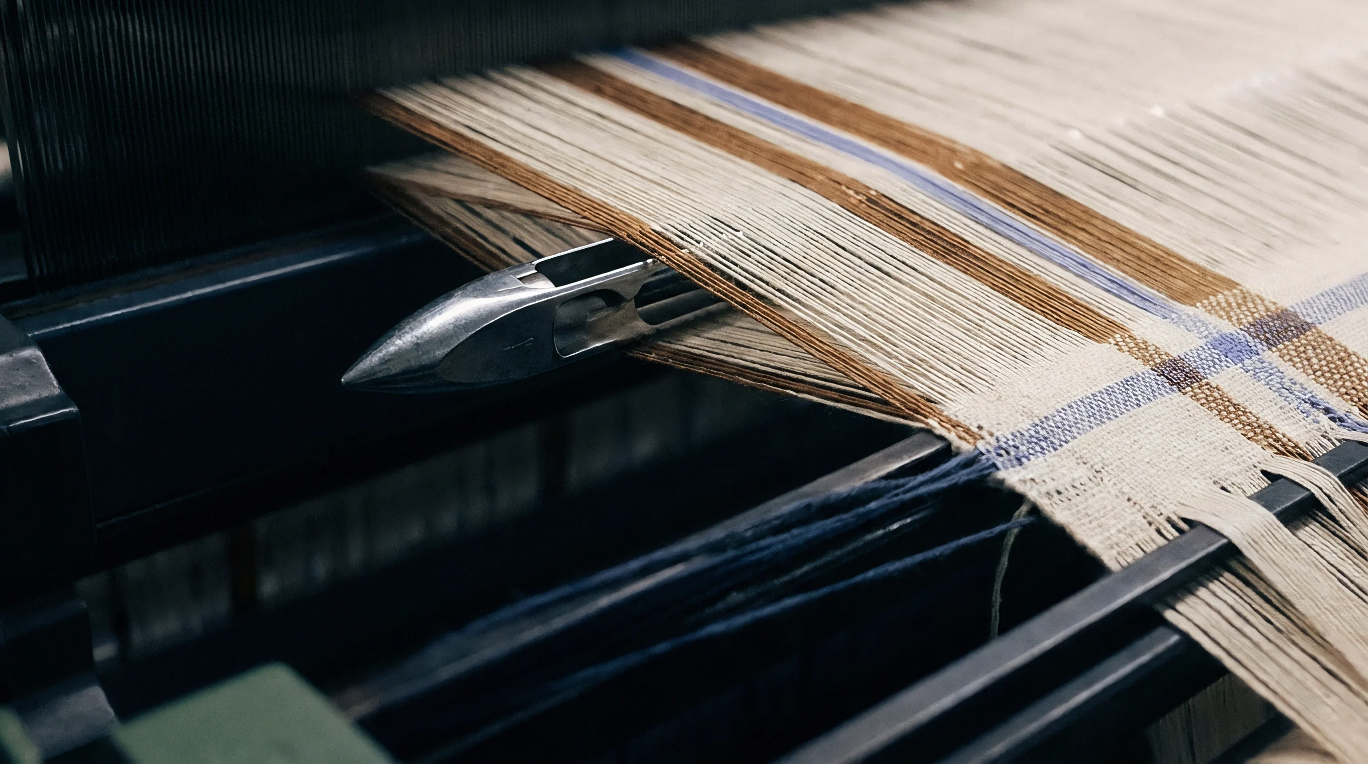
The velocity of a weft yarn propelled through a profile reed channel reaches forty metres per second within fifteen milliseconds of valve actuation. Air jet insertion relies on drag forces generated by high-velocity compressed air streams passing along the surface of the yarn. The initial acceleration phase creates a steep rise in tensile load as the yarn overcomes static inertia on the pre-winder drum.
Main nozzle pressure drives this initial phase, launching the tip of the pick into the shed. Peak loads spike at arrival.
Relay nozzles arranged sequentially along the reed profile maintain filling speed across the weaving width. Each relay nozzle fires in timed groups, creating a moving wave of high-velocity air that carries the yarn payload across reed widths exceeding three hundred and sixty centimetres. Off-center nozzles induce severe friction.
When nozzle alignment deviates by more than half a millimetre from the reed axis, the air stream forces the yarn against the aluminum walls of the profile reed, introducing kinetic friction that opposes insertion force. Profile reeds channel the air stream.
During the propulsion phase, aerodynamic drag varies directly with yarn hairiness and surface friction coefficient. Spun cotton yarns experience greater drag force than smooth continuous filament polyesters under identical air pressure settings, demanding precise calibration of relay nozzle timing. As the yarn tip nears the right-hand selvage, main pressure subsides while terminal relay nozzles maintain leading-end stability.
The terminal phase ends abruptly when the electro-magnetic yarn stopper engages, arresting the yarn at the pre-winder drum.
| Phase | Air Pressure Range (bar) | Yarn Velocity (m/s) | Tension Magnitude (cN) | Primary Mechanical Driver |
|---|---|---|---|---|
| Launch | 3.5 – 5.0 | 0 to 35 | 25 – 45 | Main Nozzle Solenoid Actuation |
| Mid-Shed Propulsion | 1.8 – 2.8 | 38 to 48 | 12 – 20 | Sequential Relay Nozzle Groups |
| Arrival Braking | 0.5 – 1.2 | 45 to 0 | 55 – 90 | Pre-Winder Stopper Pin & Flex-Brake |
| Beat-Up Rest | 0.0 | 0 | 15 – 25 | Shed Closure and Reed Impact |
This mechanical arrest generates the highest transient tension peak in the entire insertion cycle. The kinetic energy of the moving yarn transforms into dynamic strain energy within three milliseconds. If the yarn exhibits high elastic modulus and low elongation, such as glass fiber or high-tenacity aramid, this braking peak easily exceeds the tensile breaking force of the thread, causing end breaks at the right-hand catch cord.
A thirty percent increase in relay nozzle pressure elevates peak yarn tension by nineteen percent during the acceleration window.
Managing insertion forces demands careful balancing of nozzle pressure curves against the mechanical stopping angle. High air pressures stabilize yarn flight through dense warp sheds, but elevated air speed increases yarn tension throughout the flight path. Lower pressures reduce stress on weak yarns, yet insufficient air velocity allows the yarn tip to drop, creating short picks and frequency-driven loom shutdowns.
The equilibrium between pneumatic propulsion force and mechanical braking load defines the working window for air jet insertion efficiency.
Brake
Yarn unwind dynamics on the pre-winder drum determine the initial resistance encountered as the filling tip enters the main nozzle. As the yarn unwinds from the stationary package mounted on the creel, the unwinding balloon expands and contracts, altering tension levels before air propulsion begins. Package shape alters unwind force.
Full yarn packages exert less unwinding resistance than nearly empty package cones due to shifting unwind angles and changing yarn coil sliding resistance.
Electro-magnetic yarn brakes installed on the pre-winder unit actively suppress tension spikes during the arrival phase. These devices apply physical clamping force or magnetic deflection to the yarn path milliseconds before the stopper pin engages. Braking timing governs peak stress.
Applying the brake too early decelerates the yarn tip prematurely, leading to buckled picks inside the reed channel. Applying the brake too late forces the stopper pin to absorb the total kinetic force, causing filling snapping at the right-hand selvage.
Sequential adjustment of the yarn braking cycle stabilizes peak dynamic tension across varying package diameters. Modern pre-winders utilize automated braking profiles that adjust stopping parameters as the yarn package exhausts.
- Measure baseline peak tension at the right-hand selvage using a high-frequency piezoelectric tension transducer attached to a storage oscilloscope.
- Set the pre-winder stopper pin drop angle to engage exactly five degrees before the target arrival crank angle.
- Advance the electro-magnetic brake activation timing in two-degree increments until the arrival tension peak decreases by twenty-five percent without causing pick shortening.
- Verify air valve closure timing to ensure relay nozzle pressure drops to zero precisely as the stopper pin arrests the filling thread.
Pressure drops weaken the jet. Fluctuations in the central compressed air supply line directly impair insertion stability. When air pressure at the main tank dips by half a bar during peak shed shift hours, nozzle air velocity drops non-linearly.
Yarn flight times lengthen, shifting the arrival timing into the closing warp shed. The resulting interaction between closing warp ends and the slow-moving filling tip increases mechanical abrasion, causing filamentation on low-twist synthetic yarns.
Adjustment of pre-winder balloon control rings stabilizes unwinding tension when switching between spun yarns and continuous filaments.
Dynamic tension variations also stem from micro-slubs and linear density shifts inside spun yarn lots. A thick place in a cotton yarn increases aerodynamic surface drag, accelerating the yarn faster than a nominal yarn section. This accelerated flight causes the yarn to strike the stopper pin with excess momentum, escalating peak deceleration forces.
Mills frequently attribute recurring pick direction tension streaks to unavoidable yarn count variations within the spinning lot.
Trace
Piezoelectric sensor arrays placed directly behind the right-hand selvage document the complete dynamic tension curve of each insertion cycle. The resulting voltage signal yields a real-time strain profile that exposes mechanical anomalies across individual loom picks. Tension spikes shear delicate filaments.
Analyzing these electronic waveforms allows loom technicians to distinguish between pneumatic drag errors, yarn unwinding snarls, and mechanical braking misalignment.
How Does Arrival Window Timing Shift Weft Tension?
Arrival timing governs the shape of the tension curve during the final ten percent of the crank angle cycle. When the filling yarn arrives early, it strikes the closed stopper pin while main air pressure remains fully active. This creates a secondary tension peak as the air stream continues tugging against the stationary yarn.
Late arrival causes loose picks. When the yarn arrives late, the reed moves forward during shedding while the yarn tip remains unconstrained, causing loose selvages, pick loops, and uneven pick density along the cloth fell.
| Trace Anomaly | Waveform Profile | Root Cause | Physical Defect Output |
|---|---|---|---|
| Dual Peak Arrival | Two sharp high-amplitude voltage spikes within 5ms | Premature braking followed by stopper pin impact | Right-hand filling snap-backs and fringe loops |
| Low Flight Baseline | Flat, near-zero tension curve during mid-shed phase | Insufficient relay nozzle pressure or low yarn hairiness | Wavy pick path and unstable fabric width |
| High Launch Spike | Initial acceleration voltage exceeding 80 cN limit | Pre-winder yarn brake hanging or package snagging | Left-hand weft break at main nozzle exit |
| Irregular Cyclic Shift | Sinusoidal baseline variation over 500 loom revolutions | Eccentric package unwinding or creel alignment drift | Periodic density banding visible in finished fabric |
Flight time variation directly correlates with filling tension dispersion across a production roll. A narrow arrival window spanning ten crank degrees indicates a stable insertion process with low tension variance. An arrival window expanding beyond twenty-five crank degrees signalizes uncontrolled unwind friction, inconsistent air valve response, or severe yarn linear density shifts.
- Wavy Selvages Loose weft insertion tension near the catch cords allows the selvage ends to contract unevenly during beat-up, causing edge rippling.
- Tight Picks Excessive arrival braking tension permanently strains high-stretch elastic yarns, causing localized fabric narrowness and dense pick banding.
- Filling Bar Defects Cyclic shifts in pre-winder unwind tension produce repeating horizontal bands of altered yarn crimp visible after dyeing.
- Kinky Weft Insufficient terminal tension allows the yarn tip to recoil inside the shed channel, generating snarls and double-pick defects.
Sensors register the impact spike. High-frequency digital sampling captures microsecond tension fluctuations that traditional spring-loaded mechanical meters obscure entirely. Modern monitoring platforms compute the integral of the tension-time curve for every pick, automatically stopping the loom if the total insertion stress crosses pre-programmed safety thresholds.
Whether optical flight tracking can dynamically modulate individual relay nozzle pressures in real time to offset package density variations remains an active line of mechanical investigation.
Streak
Physical defects in finished woven goods emerge directly from unequal elastic recovery across adjacent filling picks. When filling yarn experiences excessive tension during air jet insertion, the yarn undergoes temporary viscoelastic elongation. After beat-up and release from warp tension, the over-extended yarn relaxes, pulling the fabric selvages inward.
Yarn drag increases with hairiness. If adjacent picks experience varying insertion tension, the relaxation rate differs pick-by-pick, forming visible fabric width variations and pick-density bandings.
Subtle tension differences alter the structural crimp distribution between warp and weft yarns. Higher filling tension forces the warp yarns to bend around a rigid, straight weft pick, elevating warp crimp while diminishing weft crimp. This structural shift alters light reflectance across the fabric surface.
In dyed piece-goods, regions with flattened weft crimp absorb illuminant light differently than regions with high weft crimp, producing distinct shade banding without any chemical dye concentration difference.
Standard ISO 13934 testing shows warp-way tensile strength drops four percent when weft insertion tension variations exceed twelve percent across a production roll.
Air permeability tests run under ISO 9237 demonstrate that localized tension variations alter fabric pore geometry. Areas woven under high filling tension display wider inter-yarn gaps due to yarn cross-section flattening under stress. Consistent pressure yields uniform density.
Conversely, picks inserted under low tension maintain a rounder cross-section, packing tighter against adjacent picks during reed beat-up and decreasing air flow through the finished cloth.
- Maximum Dynamic Tension Limit Specify dynamic insertion tension peaks not to exceed twenty-five percent of the single-end yarn breaking strength measured under ISO 2062 conditions.
- Arrival Window Tolerance Mandate a maximum allowable flight arrival window variance of plus or minus seven crank degrees across a continuous ten-thousand-pick production run.
- Air Pressure Stability Margin Standardize loom shed main line pressure regulation within a tight tolerance band of plus or minus zero point one bar at the nozzle inlet manifold.
- Pre-Winder Brake Profile Calibration Enforce package-diameter-compensated braking profiles to maintain constant stopping deceleration from package start to cone core.
Reed alignment alters air velocity. When a weaving mill operates worn profile reeds, channel air leakage forces the technicians to increase relay nozzle pressure to compensate. This elevated pressure subjects the filling yarn to harsher air shear forces, raising hairiness levels on spun staple yarns.
The resulting raised fibers entangle with adjacent warp ends, causing weft stops and localized structural surface fuzzing. Uncontrolled weft tension variations force dyehouses to apply excessive stenter overfeed to equalize fabric width, destroying thermal efficiency and causing cross-wise shading rejections at the garment cutting table.

Yield
Compressed air generation accounts for up to sixty-five percent of the total electrical power consumed inside a modern air-jet weaving shed. Operating air jet looms at unnecessarily high pressure settings to eliminate filling stops elevates overall utility costs dramatically. Air consumption escalates at higher pressures.
Operating a loom shed of two hundred air jet frames at six bars main pressure instead of four point five bars adds substantial operating expenditure per linear metre of cloth produced.
Consider a practical operational example: an air jet loom operating at 900 picks per minute on a 190 cm reed width producing a standard cotton poplin construction. Running the relay nozzles at 2.8 bar pressure consumes roughly 22 normal cubic metres of compressed air per hour per loom. Increasing relay pressure to 3.5 bar to eliminate sporadic late-arrival filling stops elevates air consumption to 29 normal cubic metres per hour.
At an average electrical energy cost of 0.12 US dollars per kilowatt-hour for compressor operation, this pressure elevation increases energy costs by approximately 0.038 US dollars per finished metre of fabric.
| Relay Nozzle Pressure (bar) | Air Consumption (Nm³/h/loom) | Peak Tension (cN) | Stoppage Rate (stops/10⁵ picks) | Landed Energy Cost Increase ($/m) |
|---|---|---|---|---|
| 2.0 | 17.5 | 14.2 | 4.8 | Baseline (-0.022) |
| 2.5 | 20.8 | 18.5 | 1.9 | Baseline Reference |
| 3.0 | 25.1 | 24.8 | 0.8 | +0.021 |
| 3.5 | 29.4 | 32.1 | 0.5 | +0.042 |
Reducing nozzle pressures to cut energy costs carries distinct operational risks. If pressures are cut too low, insertion velocity drops, shifting the arrival timing distribution toward the shed closure limit. The resulting surge in weft stoppages reduces loom operational efficiency below acceptable commercial thresholds.
Lower loom efficiency offsets energy savings by reducing total mill yardage output over fixed labor and capital overheads.
Excessive main nozzle pressure increases air consumption without improving weft flight stability on dense warp constructions.
Optimizing the economic yield of an air jet weaving operation requires continuous matching of pneumatic pressure settings to actual yarn strain limits. Sourcing practices buying greige cloth must audit loom shed pressure profiles alongside filling stoppage logs. Verifying that a supplier maintains controlled insertion tension profiles prevents purchasing rolls tainted by latent crimp variations and cross-directional shading flaws.
Standard procurement contracts incorporating ISO 2060 yarn count tolerances alongside a maximum three-percent weft insertion tension variance clause transfer re-dyeing and width-rectification costs directly back to the weaving mill.