Analyzing Structural Warp Deflection and Beat up Force Distributions in Extreme Density Air Jet Weaving
High warp sett in air jet weaving creates severe beat-up force spikes, requiring asymmetric shed geometry and optimized profile reeds to prevent structural yarn defects.
Reed
Jamming Limits and Cover Geometry in Jet Insertion
Extreme pick density pushing against high warp sett brings the weaving process directly into the structural jamming region defined by fabric cover geometry. Air jet weaving machinery inserts weft yarns without mechanical assistance inside the shed, relying entirely on high-velocity fluid drag inside a profiled channel. When the warp cover factor exceeds 20.0 according to the Peirce calculation method, or when the fabric density ratio surpasses 0.92, the open area available for the filling yarn to clear the warp sheet contracts drastically.
High end density restricts the shed space.
The movement of the sley toward the cloth fell compresses adjacent warp threads into a rigid plane. As the beat-up point approaches top dead center, the angle between the upper and lower shed sheets must widen to allow the air stream channel clearance. Widening this angle increases the structural tension on every individual warp end.
The mechanical friction generated between the profiled metallic dents and the tightly packed warp yarns retards the forward movement of the filling yarn, creating pick arrival timing variations. Air jet weaving faces tight cover limits.
| Yarn Type | Sett (Ends/cm) | Peirce Cover Factor | Channel Pressure (bar) | Peak Beat Force (N/cm) |
|---|---|---|---|---|
| 100% Combed Cotton 15 tex | 44.0 | 17.0 | 4.2 | 18.5 |
| 100% Combed Cotton 15 tex | 52.0 | 20.1 | 5.5 | 31.0 |
| Polyester Filament 84 dtex / 72f | 60.0 | 21.9 | 6.0 | 42.5 |
| Nylon 6,6 Monofilament 44 dtex | 68.0 | 22.6 | 6.8 | 58.0 |
Main nozzle drag forces cannot overcome the mechanical interference caused by a deflected warp yarn intruding into the profile channel. When a warp thread sags due to unequal beam tension or asymmetric shed geometry, it breaks the laminar air core generated by the relay nozzles. The resulting air turbulence causes the tip of the inserted weft yarn to fold back or buckle against the warp threads.
Raising the main pressure to compensate for this obstruction escalates energy consumption while destabilizing the filling thread tip through excessive vibration.
Sley acceleration profiles must balance insertion timing windows against the physical momentum needed to drive the weft yarn into an already jammed fell structure. If the reed channel remains in the shed too long to assist weft insertion, the available time window for beat-up shrinks. Shortening the beat-up angle forces the sley crank mechanism to impart higher acceleration to the reed.
This mechanical impulse amplifies the force spikes experienced by both the machine frame and the warp threads at the precise millisecond of fell impact.
Machine builders often state that insertion failure in ultra-dense styles stems entirely from inadequate air pressure settings rather than structural warp jamming. Technical analysis proves that pneumatic force cannot substitute for mechanical clearance inside the shed zone.
Strain
Dynamic Warp Deflection during Sley Impact
Peak tension spikes occurring between 340 degrees and 360 degrees of the loom crank cycle determine whether a warp thread survives beat-up without strand fracture or surface filament breakage. Warp yarns deflect under heavy sley impact. The structural resistance offered by the existing cloth fell acts as a solid barrier during extreme density weaving.
The newly inserted weft thread must be forced into the structural cross-over points between adjacent warp threads, forcing the warp sheet to elongate instantaneously to accommodate the new insertion.
Peak warp strain during beat-up on 60 ends per centimetre cotton poplin exceeds three percent under a five-bar channel insertion pressure profile.
The mechanical compliance of the warp yarn determines its structural deflection path. Continuous filament nylon yarns deform elastically during beat-up, absorbing peak impact forces through momentary axial extension before relaxing back into the woven matrix. Ring-spun cotton yarns exhibit lower ultimate elongation, resulting in higher localized stress concentrations at the reed wire contact points.
Excessive beam tension breaks fine filament ends.
- Reed Mark Formation occurs when individual warp threads deflect unevenly across adjacent dent wires, producing vertical density bands along the longitudinal axis of the finished cloth.
- Shedding Clearance Failure arises when peak warp stress exceeds the dynamic lifting capacity of the heald frames, leaving loose threads in the insertion channel.
- Filament Fraying develops as high beat-up force forces textured multifilament yarns against metallic reed surfaces under extreme lateral compression.
- Stoppage Spikes occur when localized warp end tension exceeds yarn single-strand tensile strength during fell contact.
Asymmetric shed positioning alters the tension differential between the top and bottom warp sheets. Elevating the back-rest roller relative to the breast beam increases the tension on the lower warp sheet during shed opening. This unequal tension forces the lower sheet to remain taut while the upper sheet slacks slightly during beat-up.
The slack upper threads yield easily, allowing the weft yarn to slip over the crossover points and slide into place under lower total beat-up force. High picks per inch push reed capabilities.
Incorrect back-rest positioning combined with excessive warp line tension produces severe structural crimp imbalance, leading to uncontrolled fabric width contraction and chronic edge-tear defects during downstream dyeing processes.
Vector

Force Decomposition at the Fabric Fell
Analyzing the force vectors present during the beat-up cycle reveals how sley momentum translates into longitudinal fabric compaction. The primary force vector acts parallel to the warp sheet, pushing the inserted weft yarn toward the cloth fell. A secondary vertical vector acts perpendicular to the cloth plane, attempting to displace the fabric fell upward or downward depending on the angle of the reed at the moment of contact.
Peak tension shifts the cloth fell forward.
Dynamic friction between the warp and filling yarns opposes the forward motion of the weft thread. As the filling yarn approaches the fully jammed condition, this frictional resistance grows exponentially. The relationship between the applied beat-up force and the resulting fell displacement depends on the structural flexural rigidity of the warp threads, the yarn cross-sectional flattening, and the elastic modulus of the woven sheet already formed on the breast beam.
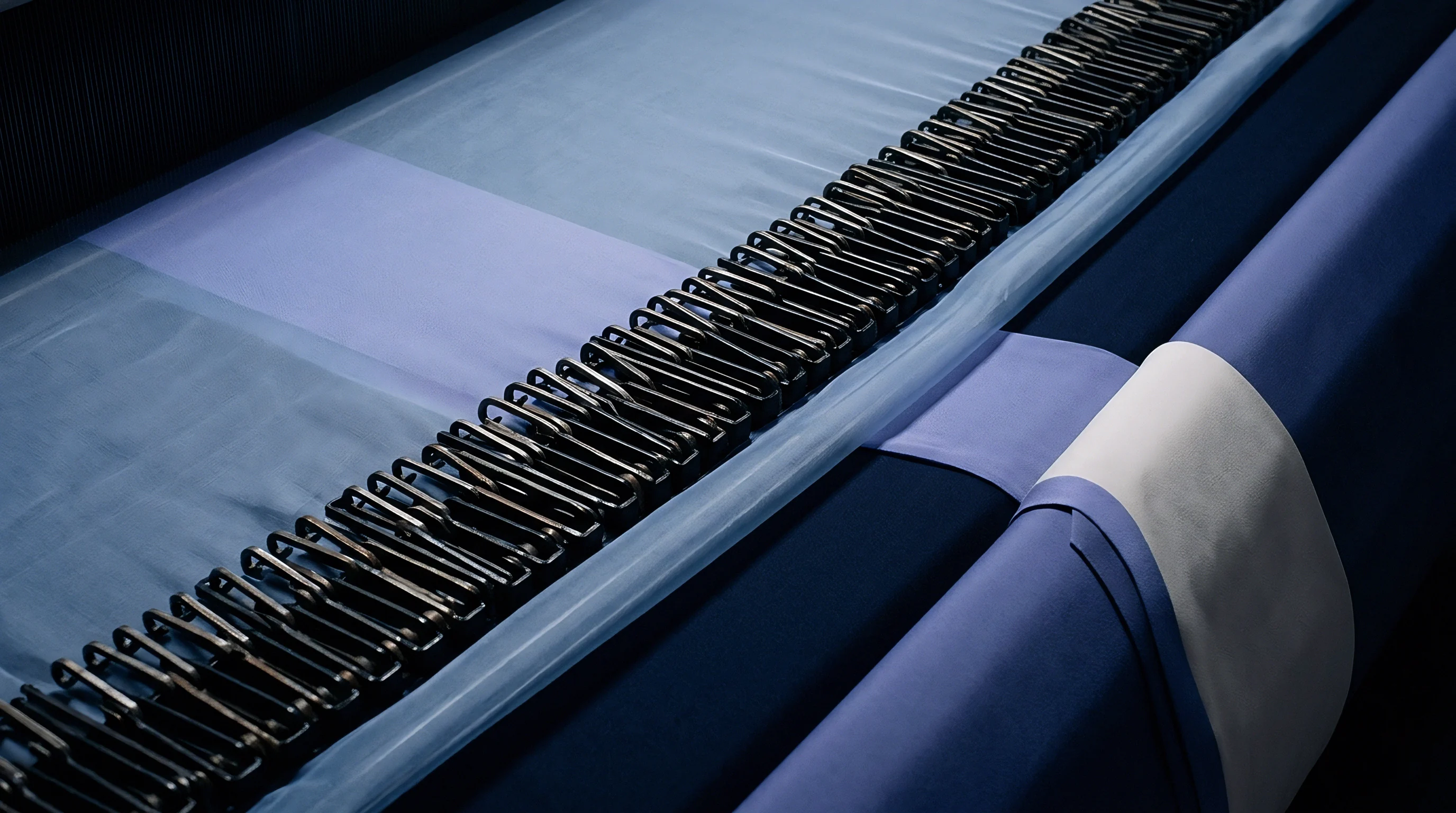
Why Does Fabric Fell Displacement Shift Beat up Peak Timing?
Fabric fell displacement occurs when the entire woven cloth sheet moves forward on the loom table under the impact of the sley. When the resistance of the inserted weft thread exceeds the static warp tension held by the let-off and take-up systems, the fell yields horizontally. This movement delays the point of maximum yarn compaction to a later crank angle, closer to top dead center.
The contact duration between the reed dent wires and the cloth fell lengthens, increasing the thermal and mechanical stress on the warp threads.
To quantify the magnitude of these dynamic forces, engineering calculations model the sley mechanism as a four-bar linkage subject to rotational acceleration. Take a representative extreme density construction: a 190 cm reed width weaving a 100% combed cotton fabric with 68 ends/cm and 48 picks/cm, operating at 800 revolutions per minute. Assume a sley crank radius of 42 mm, a connecting rod length of 210 mm, and an effective reciprocating mass of 38 kg for the sley bar and reed assembly.
At a crank angle of 352 degrees (8 degrees before top dead center), the linear velocity of the reed bar drops rapidly, producing a maximum linear deceleration of approximately 280 m/s². The inertial force generated by the reciprocating mass equals 10.64 kN. Distributed across the 1.9-metre working width, this produces a theoretical peak dynamic impact capacity of 5.6 kN per metre of cloth width.
Subtracting the internal friction of the temple holders and the elastic compliance of the warp sheet leaves an effective beat-up force of 4.1 kN/m acting directly on the fabric fell.
A fabric fell that yields more than two millimetres under sley impact loses ten percent of its structural weft density before entering the take-up motion.
Increasing the static warp tension minimizes fell displacement but increases the baseline stress carried by every single yarn end. A balance must be maintained where static warp tension provides sufficient resistance to hold the fell steady, while avoiding baseline stress levels that cause tension fatigue during high-speed shedding.
Lowering sley mass while increasing angular momentum preserves the kinetic energy necessary for fell compaction without subjecting the loom frame to destructive low-frequency vibration.
Clamp
Hardware Configurations for Ultra-Dense Weaving
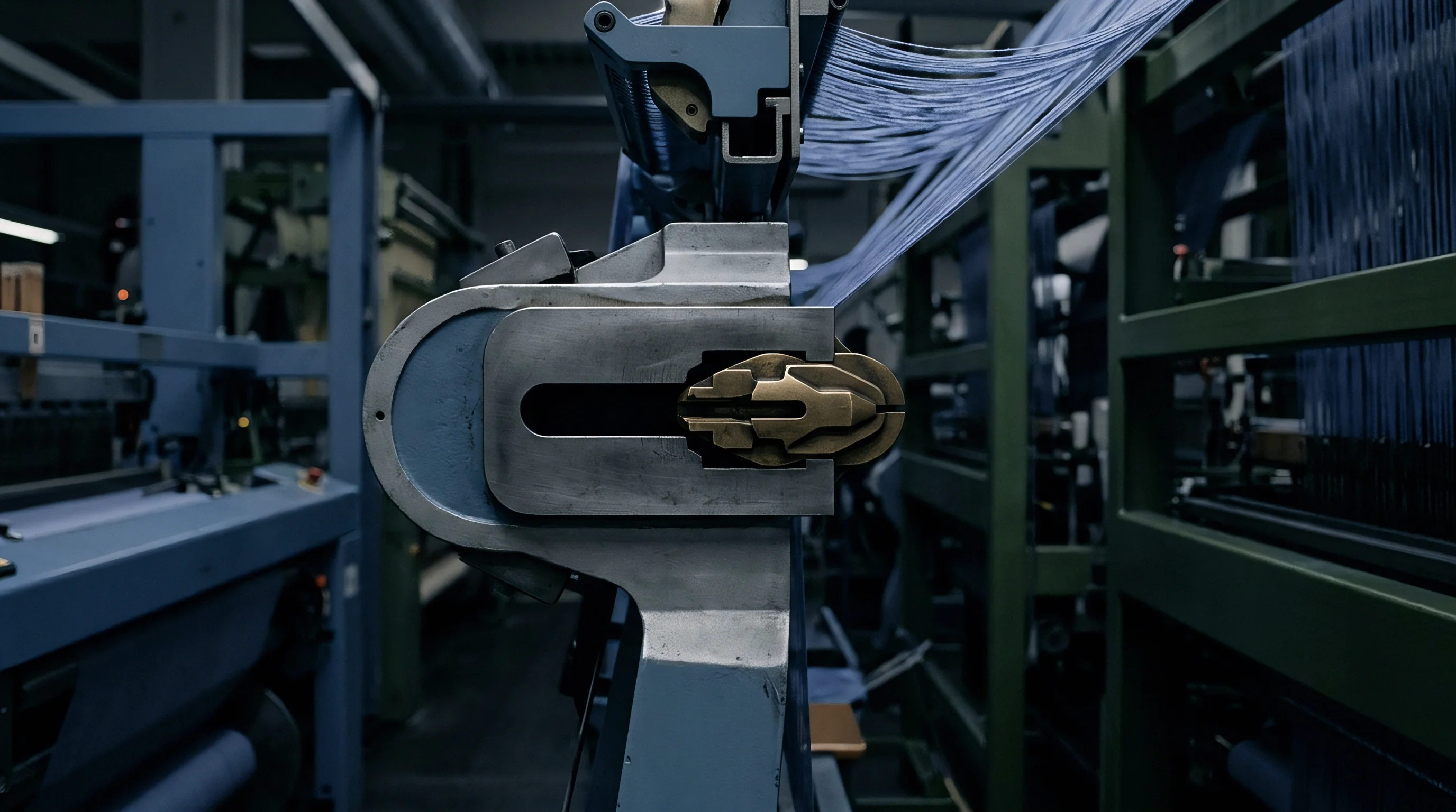
Executing high-density insertion requires specialized loom motion controls designed to absorb severe mechanical shock loads. Conventional whip rolls bow centrally under intense beat-up resistance, causing non-uniform warp tension across the loom width. Heavy-duty hydraulic or pneumatic back-rest damping systems counteract this deflection by maintaining uniform axial stiffness across the entire beam width.
Dynamic shed geometry alters beat force peaks.
| Fabric Build | Temple Roll Rings | Pin Angle (deg) | Dent Profile Type | Air Pressure (bar) |
|---|---|---|---|---|
| High Sett Down-Proof Cotton | 22 Rings / Rubber | 15.0 | Conical Channel | 5.2 |
| Ultra-Dense Micro-Filament Nylon | 32 Rings / Steel Pins | 22.5 | Tapered Relief | 6.4 |
| Industrial Aramid Filter Cloth | Full-Width Ring Temple | 0.0 | Flat Surface Steel | 7.0 |
Standard temple rolls fail to hold fabric width when weft density reaches jammed conditions. Specialized multi-ring temples featuring forward-angled steel pins must grip the selvedge and body edges securely. Proper temple selection prevents fabric edge tear.
The temples must prevent the woven fabric from snapping back inward as the reed recedes, maintaining lateral width to prevent warp end crowding at the selvedges.
- Mount high-rigidity back-rest roller assemblies with dual-end hydraulic load sensors to establish baseline warp tension uniformity.
- Align the heald frames to create a asymmetrical shed geometry, elevating the frame bridge by 12 mm to 15 mm above the standard center line.
- Calibrate the electronic let-off system to respond within three milliseconds to peak tension feedback signals captured during sley impact.
- Install a specialized tapered profile reed to reduce air loss inside the insertion channel while providing relief to deflected warp ends.
- Adjust temple ring angles and spring tensioning to eliminate selvedge bowing during the fell compaction phase.
- Set relay nozzle firing timing to terminate two degrees earlier relative to standard settings to prevent air stream interference during fell contact.
Profile reed design requires precise engineering when selecting dent wire thickness and channel dimensions. Thinner dent wires increase the open air channel volume, reducing friction against the warp ends. However, if the dent wire thickness falls below 0.35 mm, the wires deflect laterally under heavy beat-up force, producing visible reed marks and structural density variation across the fabric width.
Can real-time optical sensing at the fabric fell adjust let-off speed quickly enough to eliminate density variations across long bulk runs?

Crack
Downstream Defect Verification and Structural Quality
Physical defects originating from excessive beat-up stress or uncompensated warp deflection often remain undetected on the greige inspection frame. Heavy beat forces accelerate machine bearings wear. These latent defects become prominent during wet processing steps like desizing, scouring, and dyeing.
When a fabric with localized warp deflection variations passes through a continuous dye liquor, the uneven yarn compression zones absorb dye liquor at different diffusion rates.
| Defect Name | Physical Root Cause | Detection Method | Acceptance Limit |
|---|---|---|---|
| Warp Streak / Reed Line | Lateral dent wire deflection under force | ISO 105-J03 CIELAB Color Difference | Delta E < 0.60 across width |
| Fell Slub / Stop Mark | Fabric fell recoil following loom interruption | ISO 13934-1 Strip Tensile Test | Max 5% strength drop at mark |
| Edge Bowing / Skewing | Uneven lateral temple holding force | ISO 3951 Skew Measurement Method | Max 1.5% total fabric width skew |
| Micro-Filament Rupture | Frictional abrasion at reed wire contact point | ISO 12947 Martindale Abrasion | No end breakdown under 20,000 rubs |
Warp ends subjected to localized over-stretching lose their elastic recovery capacity. During high-temperature jet dyeing, these over-strained yarns undergo differential thermal shrinkage compared to adjacent ends that experienced lower beat-up tension. Dye bath penetration drops in dense zones.
The resulting fabric exhibits visual bandings known as structural warp streaks, which cannot be leveled by chemical dye leveling agents.
Laboratory tensile strength profiles across the width of ultra-dense fabrics reveal strength drops up to twelve percent in zones adjacent to the temple rings.
Testing laboratories isolate structural warp deflection defects by evaluating tensile strength uniformity, dimensional stability after laundering, and surface abrasion performance. Standardized testing must be performed according to ISO 13934-1 for strip tensile properties and ISO 12945-2 for pilling and surface degradation. Variations in warp density or crimp ratio directly impact test results across different regions of the roll width.
To verify structural compliance before authorizing bulk orders, buyers must integrate rigorous audit steps into their fabric purchase agreements. The specification dossier must explicitly state the minimum allowable physical performance parameters for high-density constructions.
- Warp Crimp Uniformity must remain within a tolerance band of plus or minus 0.4% across the usable cuttable fabric width when measured under ISO 7211-3.
- Maximum Fell Displacement during loom stop-start cycles must not exceed 0.5 mm to prevent visual pick density banding.
- Selvedge-to-Center Density Differential must not exceed 1.0 pick per centimetre across the entire finished roll length.
- Surface Filament Fraying Index evaluated under 50x optical magnification must show zero broken filaments per square metre of greige cloth.
Standard purchase contracts must mandate that any roll exhibiting systematic warp streak defects exceeding a CIELAB Delta E of 0.60 across the cuttable width will be rejected without mill rework allowances.

Tariff
Financial Mechanics and Production Route Economics
Manufacturing ultra-high density fabrics on air jet equipment introduces distinct cost penalties that alter the landed cost per finished metre. Loom speed must be reduced to accommodate the prolonged beat-up phase and reduce warp end breakages. Running a loom at 650 RPM instead of its rated 900 RPM speed reduces daily plant output by nearly twenty-eight percent, directly inflating the fixed overhead allocation per metre produced.
Energy consumption scales exponentially with increasing pick density. Air jet looms weaving dense constructions require compressor line pressures up to 7.5 bar to sustain filling insertion through narrow shed openings. Auxiliary main nozzles and relay nozzles must fire for longer angular durations, elevating total air volume consumption from 0.8 m³/min to over 1.4 m³/min per machine.
Compressed air generation represents one of the highest operational costs on the weaving floor.
Tooling and maintenance costs increase rapidly under severe beat-up conditions. Profile reeds constructed with hardened stainless steel dent wires and specialized wear coatings cost up to three times more than standard profile reeds. The operating lifespan of these specialized reeds drops by forty percent when continuously subjected to high-density filament or high-count spun yarn insertion.
Loom frame components, including sley bearings, crank arms, and whip roll mountings, demand shortened lubrication and replacement schedules.
Order minimums for custom high-density styles must account for the specialized loom setup time and reed installation costs. Converting a standard air jet loom to run extreme pick density builds requires up to twelve hours of technician setup, shed re-alignment, and pneumatic calibration. Sourcing practices must evaluate these operational friction factors when negotiating bulk supply agreements, factoring machine capacity, power draw, and reed replacement cycles into the final agreed price per metre.