Warp Yarn Tension Uniformity in High Speed Sectional Warping
Maintain creel tension variance under eight percent to eliminate differential yarn elongation and prevent warp barre across high-speed sectional beaming runs.
Creel
Package unwinding tension on a high-speed V-creel running 500 metres per minute shows immediate divergence between full packages at twenty-four millimetres diameter and exhausted packages at sixty millimetres diameter. The difference in balloon height produces an unchecked variation in unwinding drag across the yarn bank. A 50-tex combed cotton yarn experiences an unwinding tension rise from twelve centinewtons at full cone down to eighteen centinewtons near cone transfer.
That six-centinewton jump alters the elongation of individual warp ends before the collection reed gathers the sheet.
Modern sectional warping operations demand delivery speeds between 400 and 1000 metres per minute. At these rotational velocities, centripetal force acts directly on the yarn balloon, throwing filaments outward against adjacent positions. Ceramic eyelets, stop-motion drop wires, and guide bars introduce cumulative friction points.
Each 90-degree wrap angle around a stationary guide multiplies line tension by an exponential factor governed by the friction coefficient of the yarn against the contact material.
A tension spread exceeding 12 percent across individual package positions at 600 metres per minute causes differential crimp in downstream flat goods.
Static creel layouts generate positional tension gradients because the warp ends originating at the creel rear traverse up to eighteen metres of guide rails. Those positioned at the front traverse less than two metres. Parallel creels amplify this variance unless compensating tension regulators maintain opposing drag profiles.
V-shaped creels mitigate the angle of entry into the lease reed, yet inner row packages remain subject to boundary layer air drag generated by the moving sheet. Creel fans maintain clean yarn paths. Air currents displace travelling ends.
- Package Density Variance occurs when yarn packages wound at differing bobbin presses exhibit uneven radial hardness, causing localized draw-off resistance during high-speed take-off.
- Guide Path Misalignment introduces parasitic wrap angles across intermediate porcelain eyelets, elevating individual end tension above the allowable operating band.
- Accumulated Sizing Dust settles within tensioning disc collars, locking rotating plates into fixed friction blocks that abrade running filaments.
- Static Charge Build generates repulsive forces across adjacent synthetic filaments, producing lateral flutter that destabilizes the unwinding balloon against neighboring package cones.
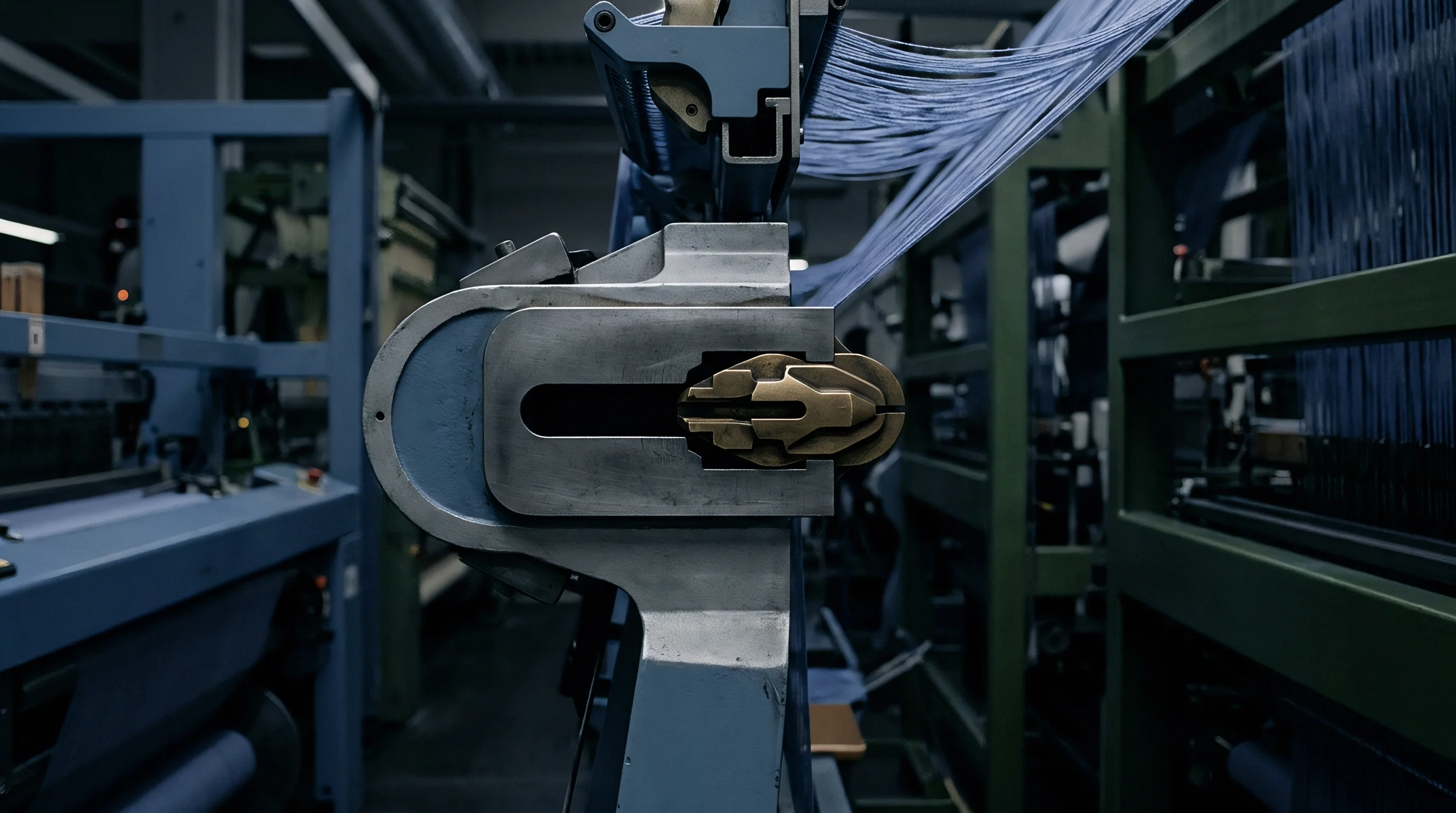
Equalizing draw-off resistance requires active, central regulation at every creel post. Pairs of opposing tension discs loaded by centralized pneumatic bladders or electromagnetic brakes deliver matched mechanical pressure to each running end. When individual positions drift due to wear or debris, the resulting tension dispersion passes directly onto the sectional warper drum.
Downstream looms suffer elevated warp breaks, irregular shed openings, and permanent selvage wave that condemns entire cloth rolls to secondary off-grade inventories.
Friction
Capstan effects dictate yarn tension escalation along every stationary metallic and ceramic boundary inside the warping zone. The Euler-Eytelwein relationship demonstrates that output tension equals input tension multiplied by Euler’s constant raised to the product of contact angle and yarn-to-guide coefficient. A titanium oxide eyelet exhibiting a coefficient of 0.18 raises yarn line tension by thirty-four percent through a single 90-degree deflection.
Three successive guide bars elevate an entry tension of eight centinewtons to twenty-one centinewtons before the yarn reaches the warping table.
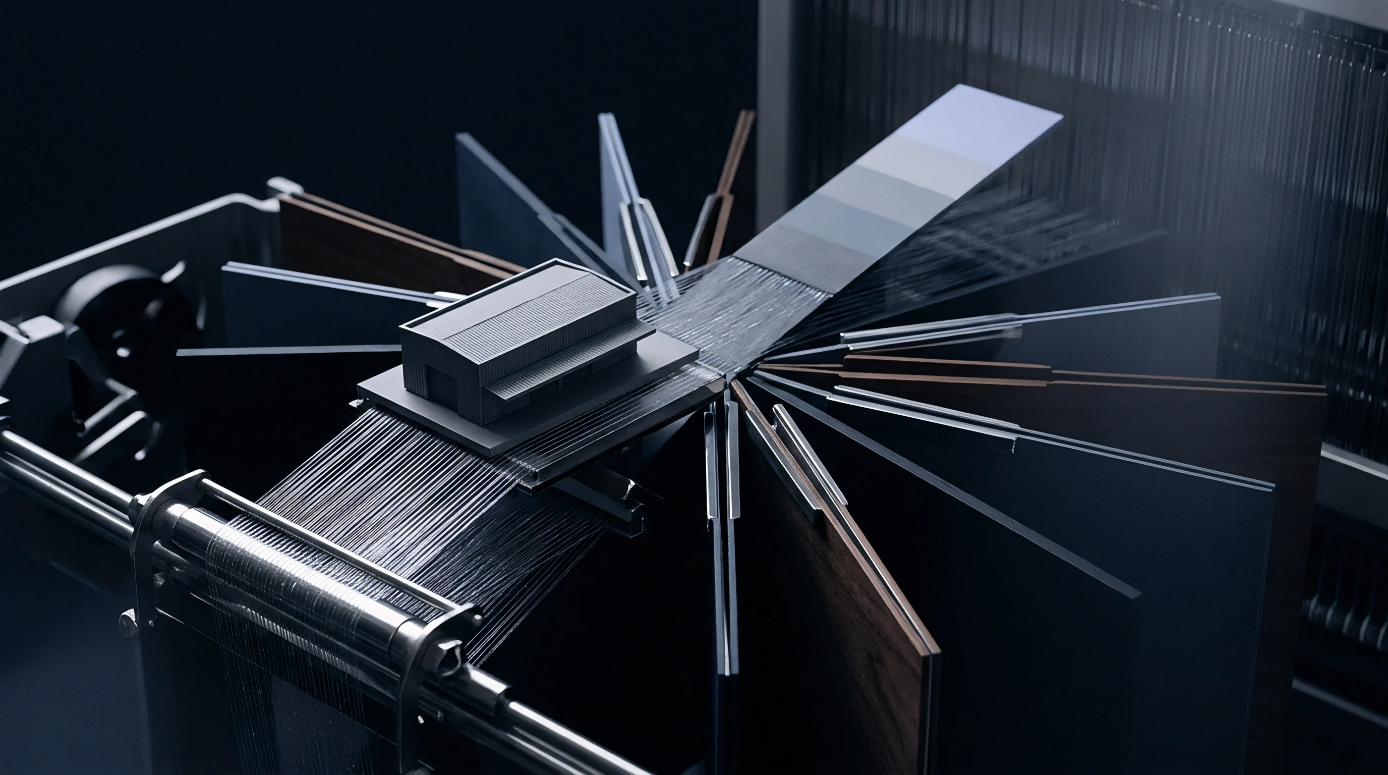
Where Do Tension Deltas Originate across Packages?
Tension variations trace back to the dynamic balloon collapse occurring as packages deplete. When the yarn package diameter shrinks, the rotational velocity of the unwinding point accelerates to match linear machine take-up speed. The balloon contracts from a multi-node shape into a taut single envelope, increasing angular velocity and mechanical drag against the package shoulder.
Without automated creel tension compensation, inner bobbin layers wind onto the warping cylinder under significantly elevated mechanical strain.
| Creel Position Distance (m) | Running Velocity (m/min) | Nominal Tension (cN) | Measured Tension Spread (cN) | Elongation Variance (%) |
|---|---|---|---|---|
| 3.0 | 400 | 14.2 | ±1.1 | 0.32 |
| 3.0 | 800 | 18.6 | ±1.8 | 0.54 |
| 12.0 | 400 | 17.1 | ±1.4 | 0.48 |
| 12.0 | 800 | 24.3 | ±2.9 | 0.86 |
| 18.0 | 400 | 19.8 | ±1.6 | 0.61 |
| 18.0 | 800 | 28.5 | ±3.8 | 1.12 |
Braking cycles expose mechanical drift. During machine deceleration from 800 metres per minute down to zero within two seconds, the rotational inertia of the individual yarn packages risks yarn overrun. Creel stop-motion response times govern slack loop formation.
Spring-loaded tension compensation arms depress instantly to absorb loose filament length, preventing cross-lacing and snarling. Ceramic guides develop microscopic grooves. Polished surfaces lose boundary lubrication under sustained synthetic filament friction, generating localized micro-welds that manifest as filament strip-back defects.
Electronic disc regulators apply inverted braking pressure to counteract balloon collapse. The centralized creel controller reduces mechanical clamping force on individual yarn tension discs proportionally as package diameter decreases. Yarn speed sensors interface with photoelectric package radius detectors, feeding closed-loop PID algorithms that actuate stepper motors across each vertical creel rail.
Uniform friction control demands constant ambient atmospheric conditioning, because relative humidity shifts above sixty percent alter the surface moisture regain of cellulosic yarns, shifting the sliding coefficient of friction across stainless steel guides by up to twenty-five percent.
Equal guide contact angles throughout the entire creel run yield identical line resistance regardless of spatial distance.
Yarn tension remains uniform only when every single contact point along the travel path matches every other contact point in angle, composition, and surface cleanliness.
Drum
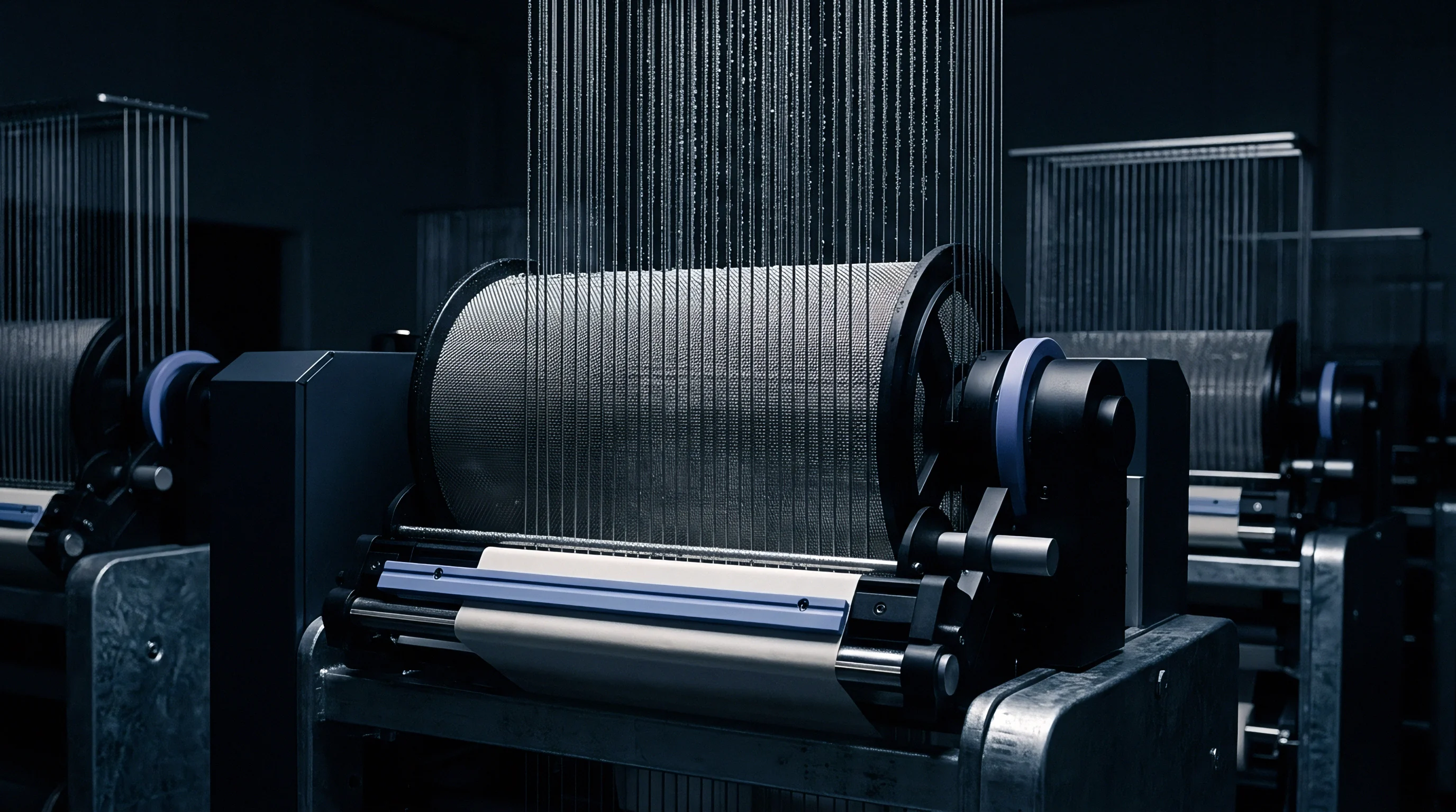
Warping cylinder construction relies on a fixed or adjustable incline cone that supports the stepped buildup of successive yarn sections. The cone angle, typically machined between nine and fourteen degrees, anchors the lateral taper of each warped band. The cross-sectional profile of each section forms a parallelogram where each successive layer of yarn must align with mathematical precision against the adjacent band taper.
Any discrepancy between the traverse speed of the warping carriage and the radial thickness accumulation of the yarn produces a non-parallel band edge.
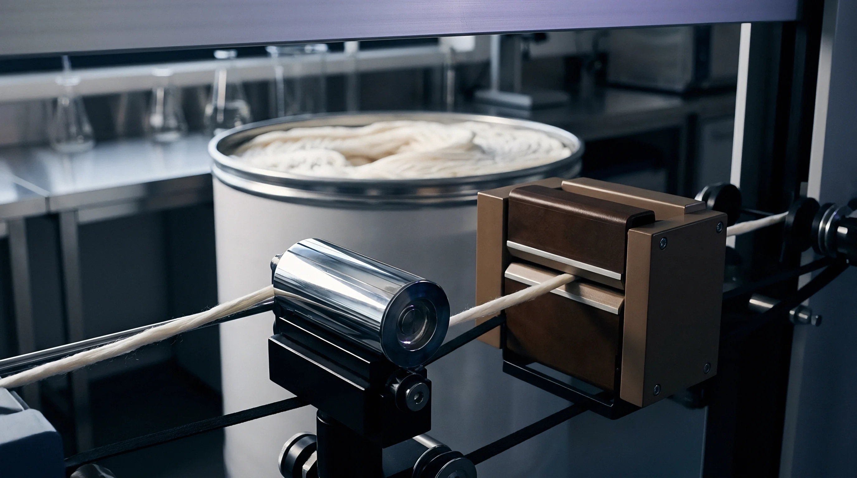
Mathematical Trajectory of Warp Band Buildup
Calculating the radial increment per revolution of the sectional drum determines the traverse speed feed rate for the warping table. Take an industrial calculation for an 800-metre warp beam run using 30-tex rotor-spun cotton yarn, structured with a sett of 28 ends per centimetre across a total warp width of 160 centimetres. The warping creel accommodates 560 bobbins, requiring four distinct warping bands to assemble the complete 2240 warp ends.
The sectional drum diameter measures 1000 millimetres with a fixed cone angle of eleven degrees, corresponding to a tangent value of 0.1944.
The winding thickness layer increment per drum revolution follows the specific volume of the yarn substrate under tension. Assuming a practical packing density factor of 0.58 grams per cubic centimetre for the tensioned 30-tex yarn package, each drum revolution adds a radial build thickness of approximately 0.048 millimetres. The carriage traverse feed rate per drum revolution equals the radial buildup divided by the tangent of the cone angle.
That establishes a feed rate of 0.247 millimetres per drum turn. A tension increase from fifteen centinewtons to twenty centinewtons compacts the yarn layers, lifting density from 0.58 to 0.64 grams per cubic centimetre. This compaction lowers radial buildup to 0.043 millimetres per turn, throwing the carriage feed rate off by ten percent.
ISO 5077 dimensional checks fail when uneven section density produces localized residual contraction bands across finished goods.
The calculation demands exact input. When the carriage traverse feed rate outpaces actual radial buildup, the yarn bank slumps downward along the cone slope, generating slack outer edges. Conversely, if the carriage traverse runs slower than the radial yarn growth, the yarn bank piles against the cone, forming high, compacted shoulders that crush underlying layers.
| Yarn Count (tex) | Cone Incline Angle (deg) | Target Line Tension (cN) | Radial Buildup Rate (mm/rev) | Carriage Traverse (mm/rev) | Density Tolerance (g/cm³) |
|---|---|---|---|---|---|
| 15 | 9.0 | 10.5 | 0.028 | 0.177 | ±0.02 |
| 30 | 11.0 | 18.0 | 0.048 | 0.247 | ±0.03 |
| 50 | 14.0 | 26.5 | 0.072 | 0.289 | ±0.04 |
| 100 | 17.0 | 42.0 | 0.115 | 0.376 | ±0.05 |
Section band matching demands electronic section width management. Modern sectional warping tables utilize high-resolution optical scanners that trace the edge geometry of the first wound band. The microprocessor maps the outer perimeter profile, storing the physical coordinates in memory to guide subsequent section placements.
The table indexes laterally after each section finishes, positioning the reed for the next band with a positional accuracy within 0.02 millimetres. If tension shifts between section three and section four, the winding circumference between those bands diverges by several millimetres over a thousand-metre run.
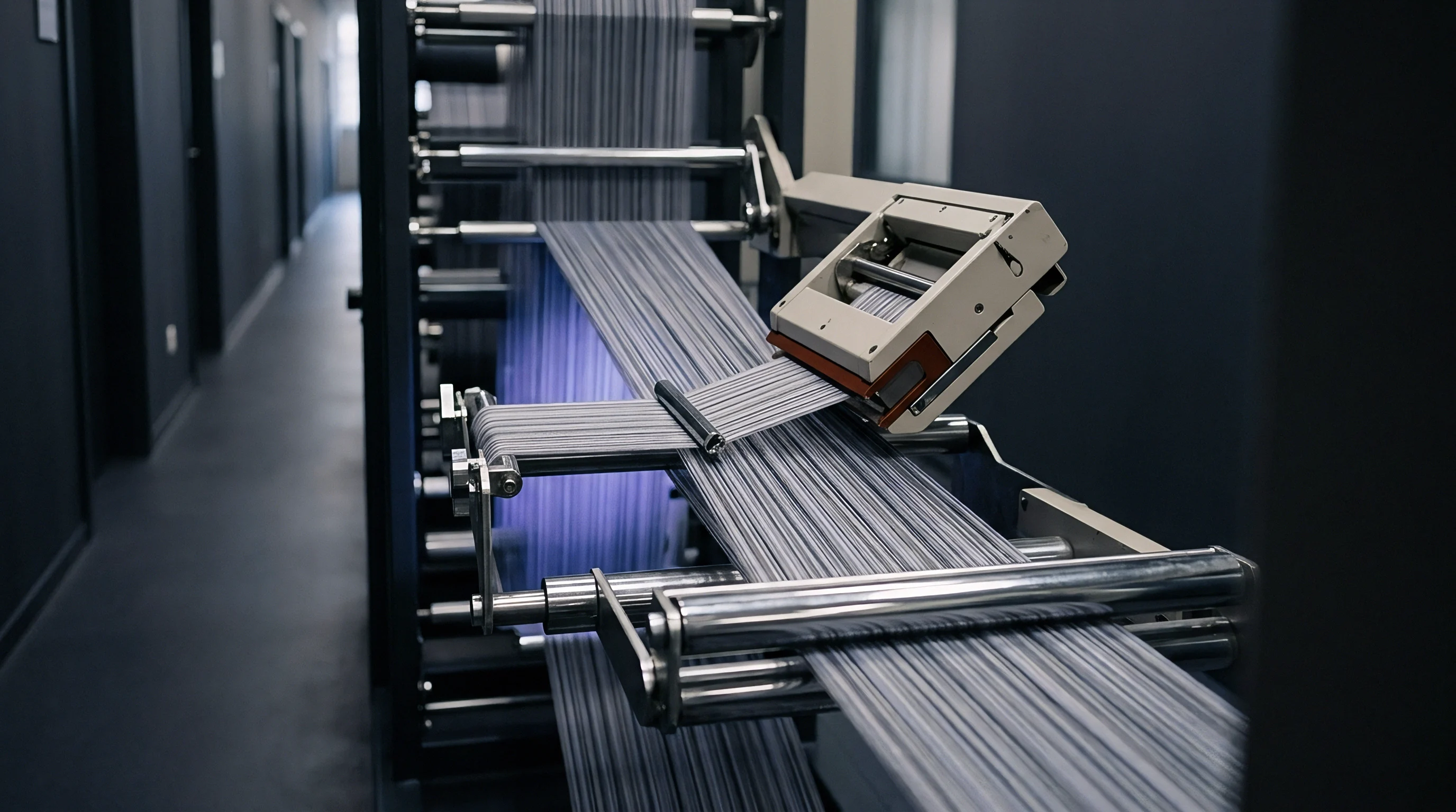
Density shifts distort warp beam packages. The beaming process transfers the assembled sheet from the warping drum onto the loom beam under flat hydraulic backpressure. If band circumferences on the drum vary due to inconsistent sectional winding tension, the beaming operation draws yarn from unequal physical lengths.
Slack ends sag into open catenaries between drum and loom beam, while over-tensioned ends carry the entire beaming motor load, stretching toward plastic deformation limits.
A supplier will typically maintain that mechanical drum leveling compensation devices eliminate minor circumferential discrepancies during the subsequent beaming pass.
Defect
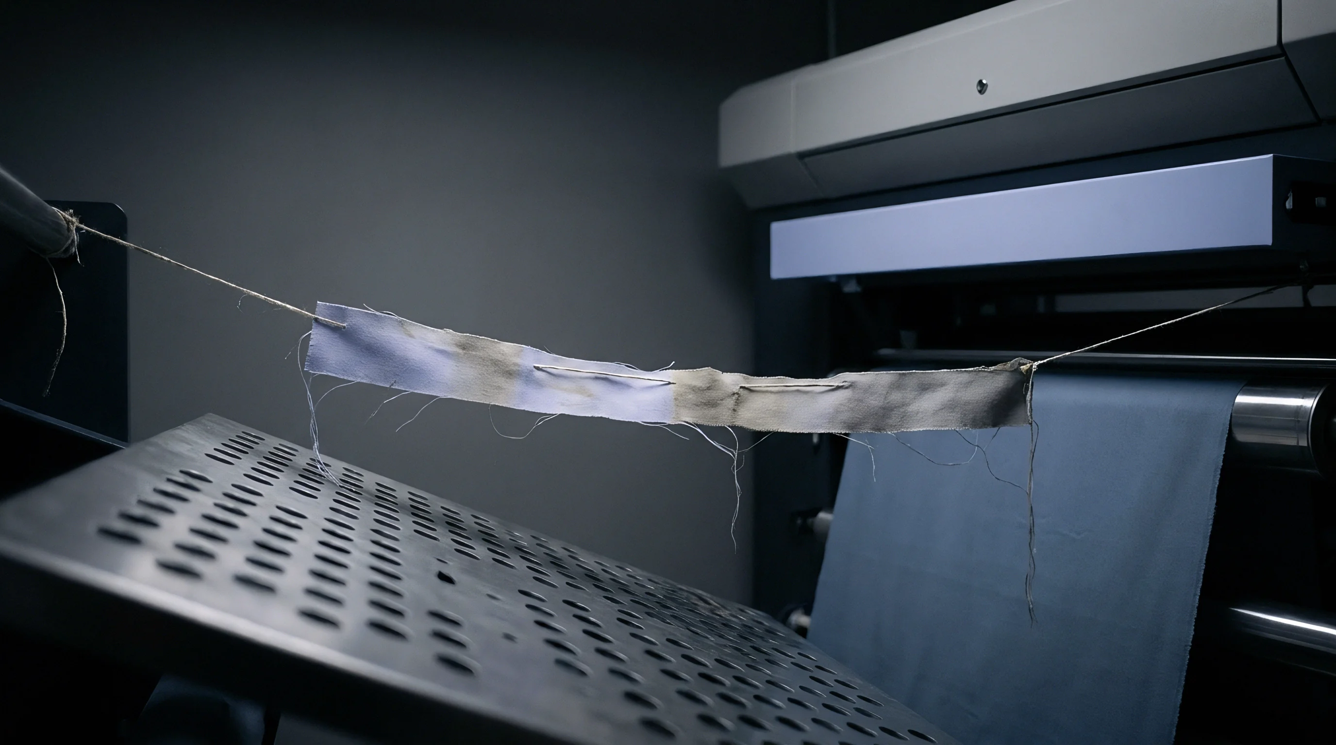
Downstream structural distortions trace directly back to uneven sectional yarn winding tensions. During rapier or airjet insertion at the loom shed, the shed opening geometry depends upon equal tension across all warp ends. When a loose band from an under-tensioned section enters the harness frames, the lower shed line sags.
The insertion projectile or air jet pulse catches the slack filaments, precipitating mispicks, end tangles, and immediate loom halts that drop weaving efficiency by twelve to fifteen percent.

What Drives Streakiness across Dyed Piece Goods?
Differential molecular orientation inside over-stretched synthetic yarns alters dye uptake rates during atmospheric piece dyeing. When polyester or polyamide filament yarns experience tension spikes exceeding 0.4 centinewtons per dtex on the sectional warper, polymer chains align axially, narrowing amorphous regions accessible to dye molecules. In disperse dyeing of polyester, these tight ends resist dye diffusion, yielding light, reflective lines down the warp length.
Loose bands accept standard dye saturation, resulting in alternating light and dark longitudinal bands known as warp stripiness or barre.
- Tension Barre marks finished goods with structural warp-direction striping caused by varying refractive index and dye site access across adjacent sectional bands.
- Waviness and Edge Curl plagues flat piece goods because differential elastic recovery between warped bands introduces localized cockling across the finished width.
- Dropwire Pinning Stoppages escalate loom downtime when slack warp ends lose sufficient tension to support electrical drop wires, triggering false halt sequences.
- Variable Pick Density occurs where taut warp bands resist crimping during beat-up, forcing the weft yarn into the softer, adjacent bands and distorting regular yarn spacing.
The lease reed separates individual ends. Off shade bands ruin commercial lots. In yarn-dyed stripes or shirting poplins, uneven tension manifests as corrugated surface topography after scouring and desizing.
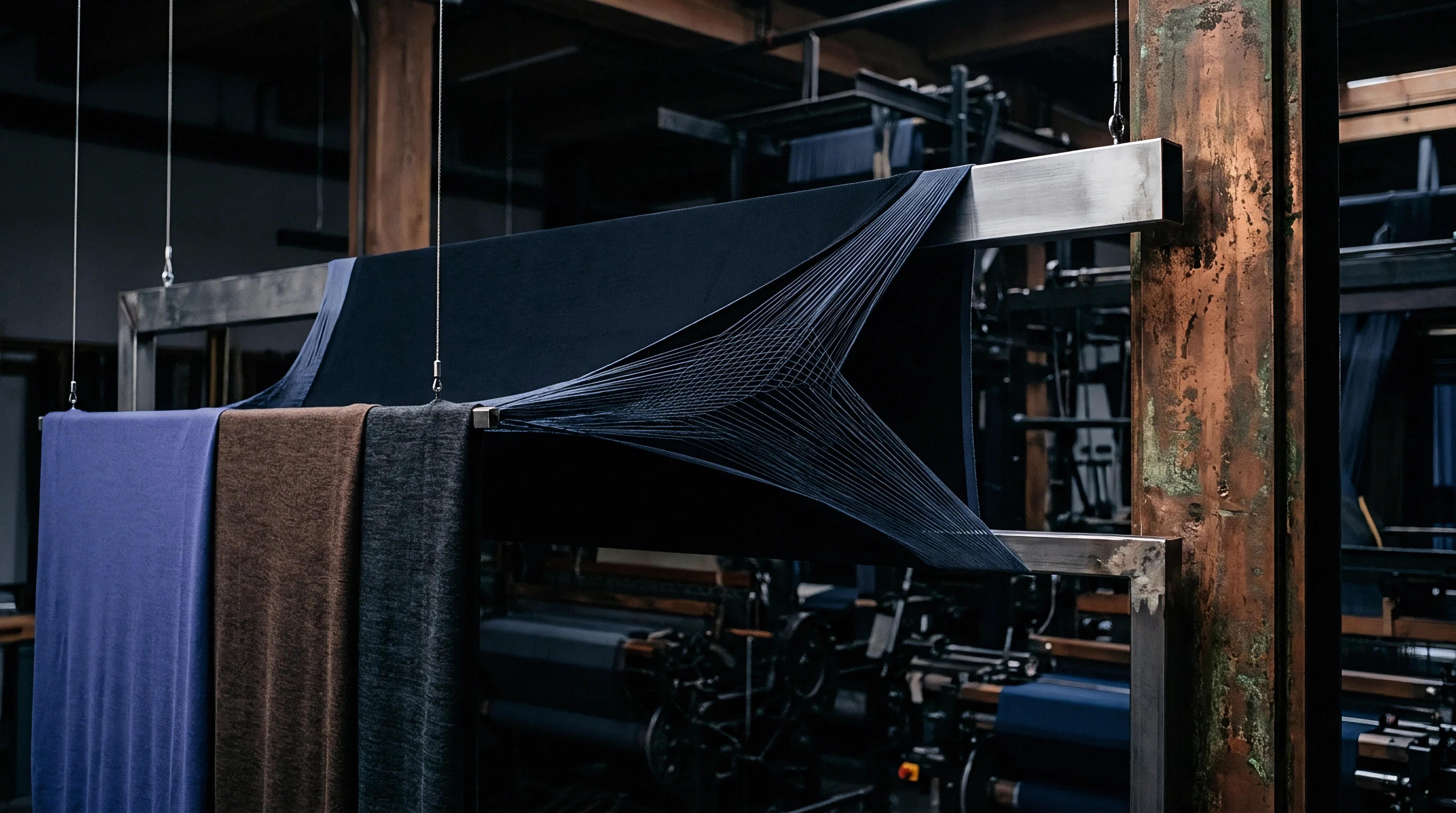
The more tensioned bands release stored elastic stress during hot aqueous wet processing, shrinking up to four percent more than adjacent relaxed sections. The resulting cloth exhibits uneven cockling that no stenter overfeed or chemical finishing resin can flatten.
Mechanical tension discrepancies exceeding five percent across section boundaries generate non-correctable optical stripiness on high-density jet-dyed broadcloth.
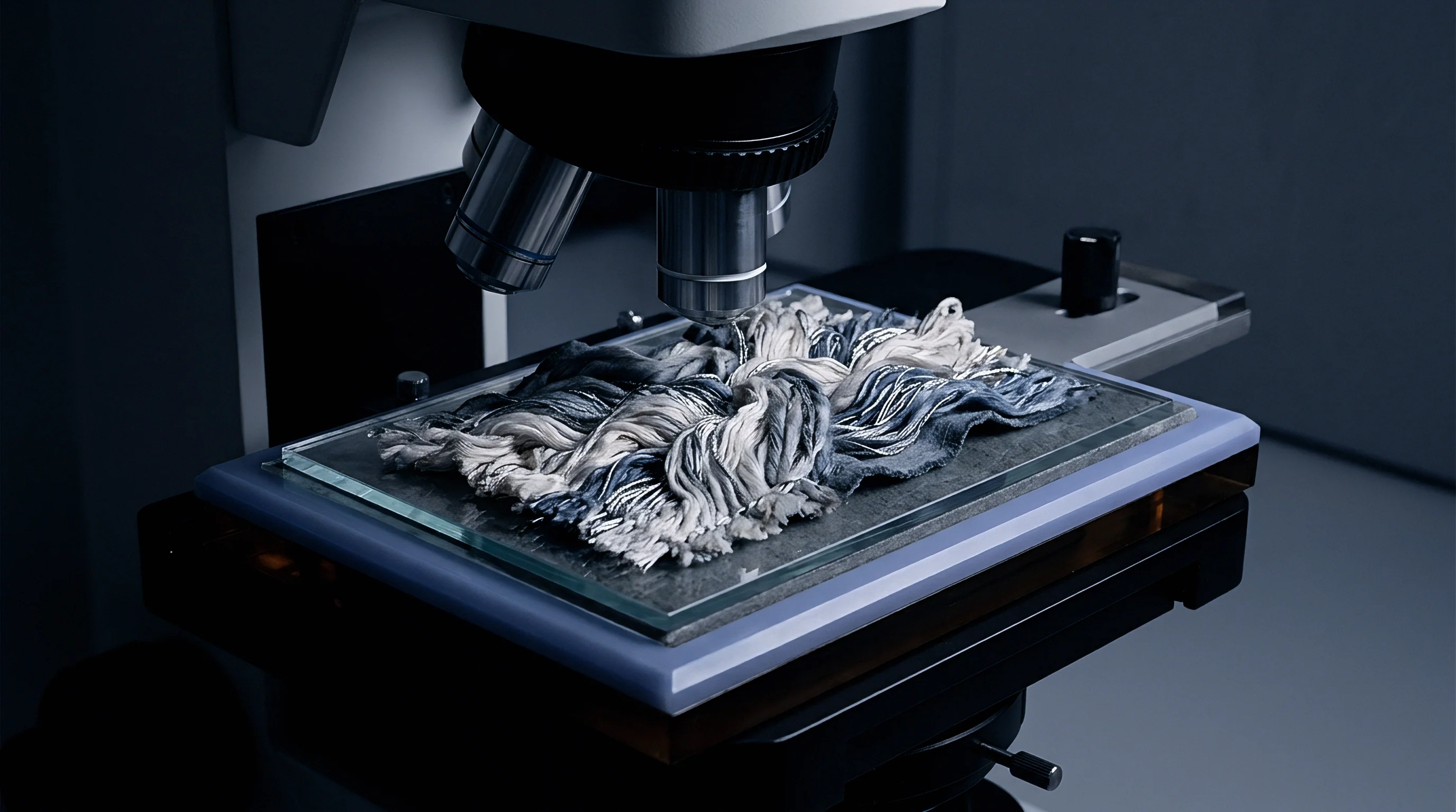
Heavier ends sink into soft bands. Commercial disputes regarding uneven dyeing routinely stall settlement negotiations when mills cannot correlate greige warp records with physical rolls. The laboratory analysis reveals altered molecular orientation under polarized light microscopy, but the economic loss is already fixed in finished warehouse stock.
The industry remains divided on whether automated optical surface scanners on sectional warpers can detect micro-elongation shifts in texturized filament yarn before beaming occurs.
Audit
Procurement contracts for high-density woven piece goods must incorporate precise warp preparation validation criteria. Sectional warping parameters directly dictate downstream weaving efficiency and shade consistency across continuous dyeing runs. The technical specification sheet needs to stipulate allowable tension variance per yarn end, drum band circumferences, and creel climate parameters during running hours.
Sourcing teams relying solely on finished greige inspection sheets miss the root cause of systemic width-wise shaded bands.
Verification Methods for Inline Tension Uniformity
Independent technical inspections utilize calibrated handheld tensiometers and stationary multichannel load cell arrays positioned along the warp sheet. Readings must occur across the outer edges and center of each active band at three operational speeds: machine start-up, continuous running speed, and machine deceleration. The allowable tension spread across any multi-end sample taken from the warping table cannot exceed a standard deviation of eight percent from nominal target value.
| Process Metric | Test Instrument | Sampling Frequency | Acceptance Band | Action on Non-Conformance |
|---|---|---|---|---|
| Individual End Tension | Electronic Tensiometer | 50 ends per section | Target ±7.5% | Calibrate creel disc pressure |
| Band Circumference Spread | Laser Distance Gauge | Every warped section | ±0.5 mm maximum | Halt and re-beam run |
| Creel Relative Humidity | Psychrometer | Continuous logged | 65% ± 3% RH | Suspend creel running |
| Yarn Elongation Drift | Tensile Bench ISO 2062 | Cone start and finish | Δ Elongation < 0.4% | Reject package delivery lot |
Section band circumference must be measured mechanically or optically after completing each band before indexing the carriage to the next section. Laser micrometers mounted parallel to the drum axis record the exact cylindrical build profile. If the radial accumulation between band two and band three differs by more than 0.3 millimetres, the operator must unwind the defective band, realign the carriage traverse pitch, and reset creel tension compensators.
Static charges accumulate on synthetic ends.
Tension drives package geometry. Beaming logs must record the hydraulic pressure on the beaming drive along with beam hardness taken across twelve points using a Shore D durometer. Hardness readings across the loom beam face must remain within a four-point band.
Variations greater than five Shore D points indicate uneven longitudinal packing, guaranteeing broken ends during high-speed insertion on modern projectile and airjet shedding machinery.
Purchase contracts should incorporate a clause stipulating that any continuous dye lot exhibiting warp-direction barre traceable to variable warp yarn elongation exceeding 0.5 percent across adjacent pattern widths triggers full lot replacement at the greige mill’s expense.