Predicting Non-Linear Weft Contraction Dynamics across Variable Speed Air-Jet Loom Sheds
Predicting non-linear weft contraction requires dynamic nozzle pressure regulation aligned with loom acceleration profiles to maintain stable fabric off-loom widths.
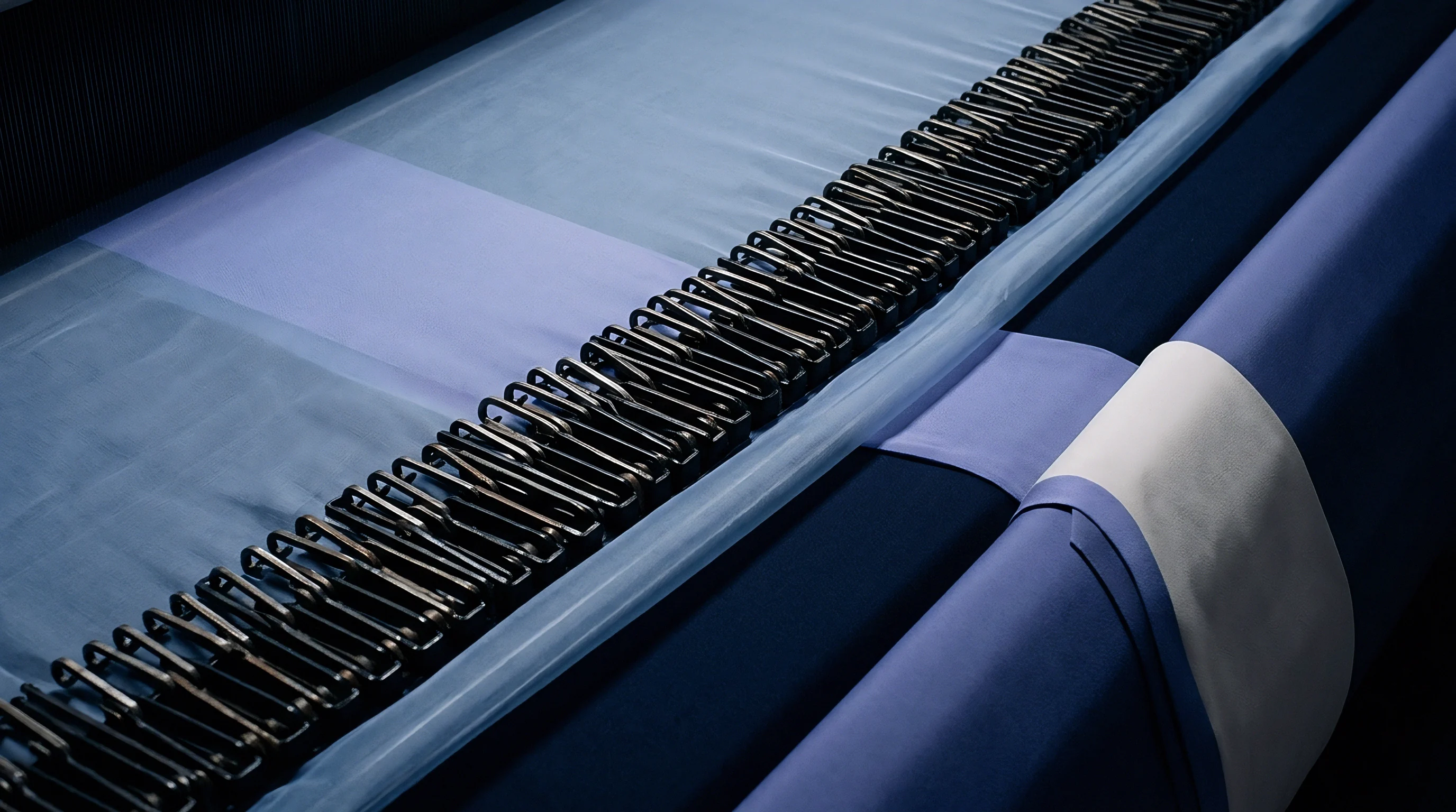
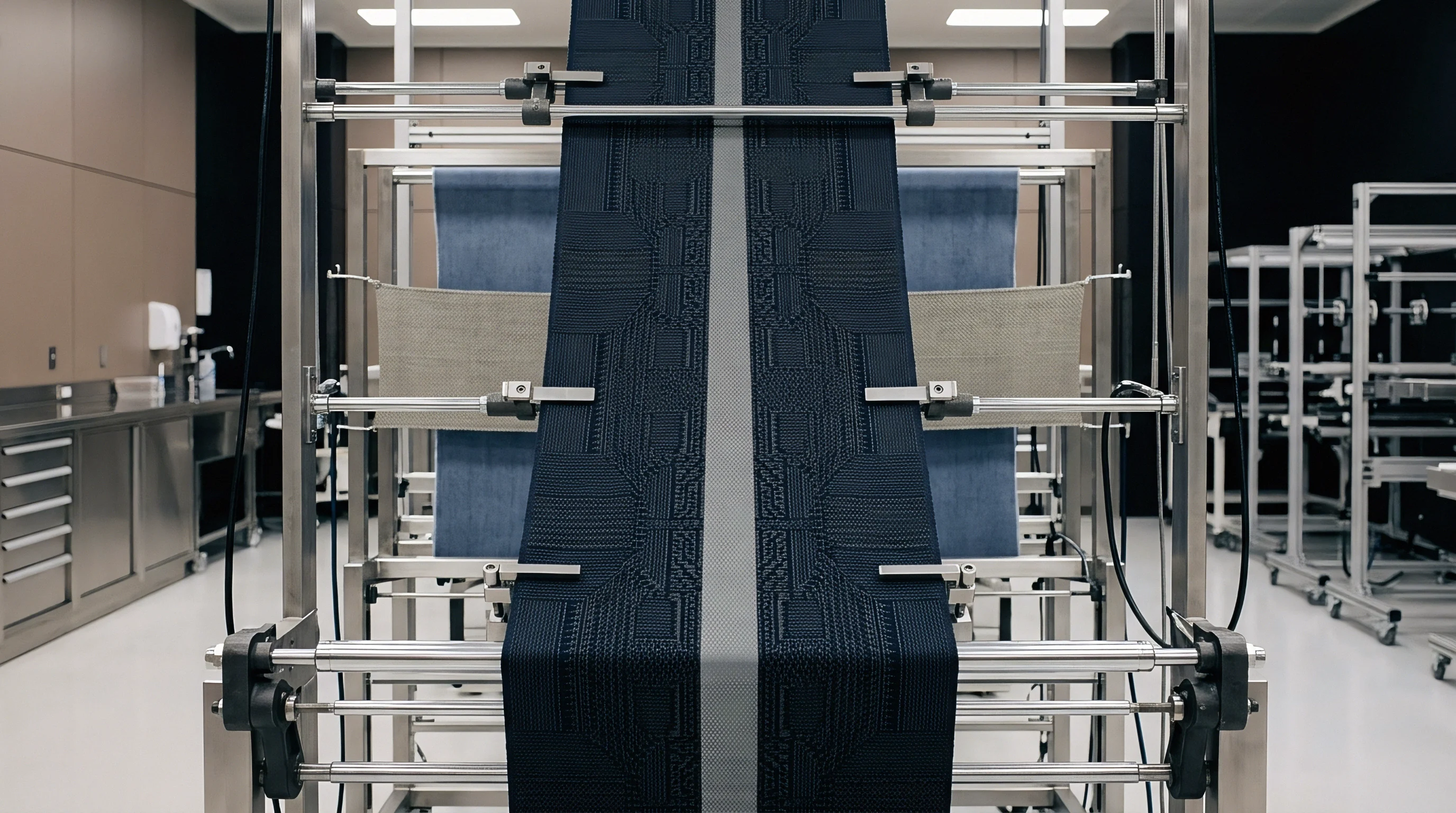
Pulse
Modern air-jet weaving machinery operates at main shaft speeds exceeding 1000 picks per minute, where the time window for weft insertion narrows to less than 25 milliseconds per machine cycle. When a loom shifts speed dynamically during ramp-up sequences, pattern variations, or automated speed reduction for low-strength yarn packages, the fluid dynamics within the propulsion system change instantaneously. Air pressure drives the yarn forward.
Compressed air supplied to the main nozzle accelerates the yarn tip from standstill to velocities above 45 metres per second within 5 milliseconds. The kinetic energy imparted to the yarn depends on air density, supply pressure, and the drag coefficient of the yarn surface.
As the machine transitions between operating speeds, fixed pneumatic profiles create inconsistent arrival times at the receiving side selvedge. At 700 picks per minute, an insertion angle of 165 degrees affords a flight duration of 14.1 milliseconds. Accelerating the main shaft to 950 picks per minute reduces the total flight window to 10.4 milliseconds at the same insertion angle.
Profile reeds channel the airflow. If solenoid valve switching response lags behind mechanical shaft acceleration, the air pulse arrives out of phase with the opening of the warp shed, causing variable retarding force along the yarn length.
Air velocity inside profile reed tunnels reaches 180 metres per second when main nozzle pressure hits 0.45 megapascals at 900 picks per minute.
Relay nozzles grouped in pairs along the reed space fire sequentially to maintain yarn velocity across widths reaching up to 340 centimetres. The stepping timing of these relay groups determines the continuous tension applied to the yarn body during flight. Variable speed algorithms adjust solenoid dwell times to prevent yarn slackening or severe tip whipping.
When air pressure remains static during speed deceleration, excessive pneumatic force stretches the weft yarn beyond its elastic yield point just before shed closure, fixing temporary extension that later recovers off-loom.
| Main Shaft Speed (RPM) | Main Nozzle Pressure (MPa) | Relay Group Pressure (MPa) | Insertion Window (ms) | Peak Yarn Velocity (m/s) | Arrival Angle Deviation (Degrees) |
|---|---|---|---|---|---|
| 650 | 0.32 | 0.28 | 15.2 | 38.5 | +1.2 |
| 800 | 0.38 | 0.34 | 12.3 | 44.2 | +0.4 |
| 950 | 0.45 | 0.40 | 10.4 | 51.8 | -2.1 |
| Data gathered on 190 cm reed width using 15 tex 100% combed cotton yarn under standard laboratory atmosphere ISO 139. | |||||
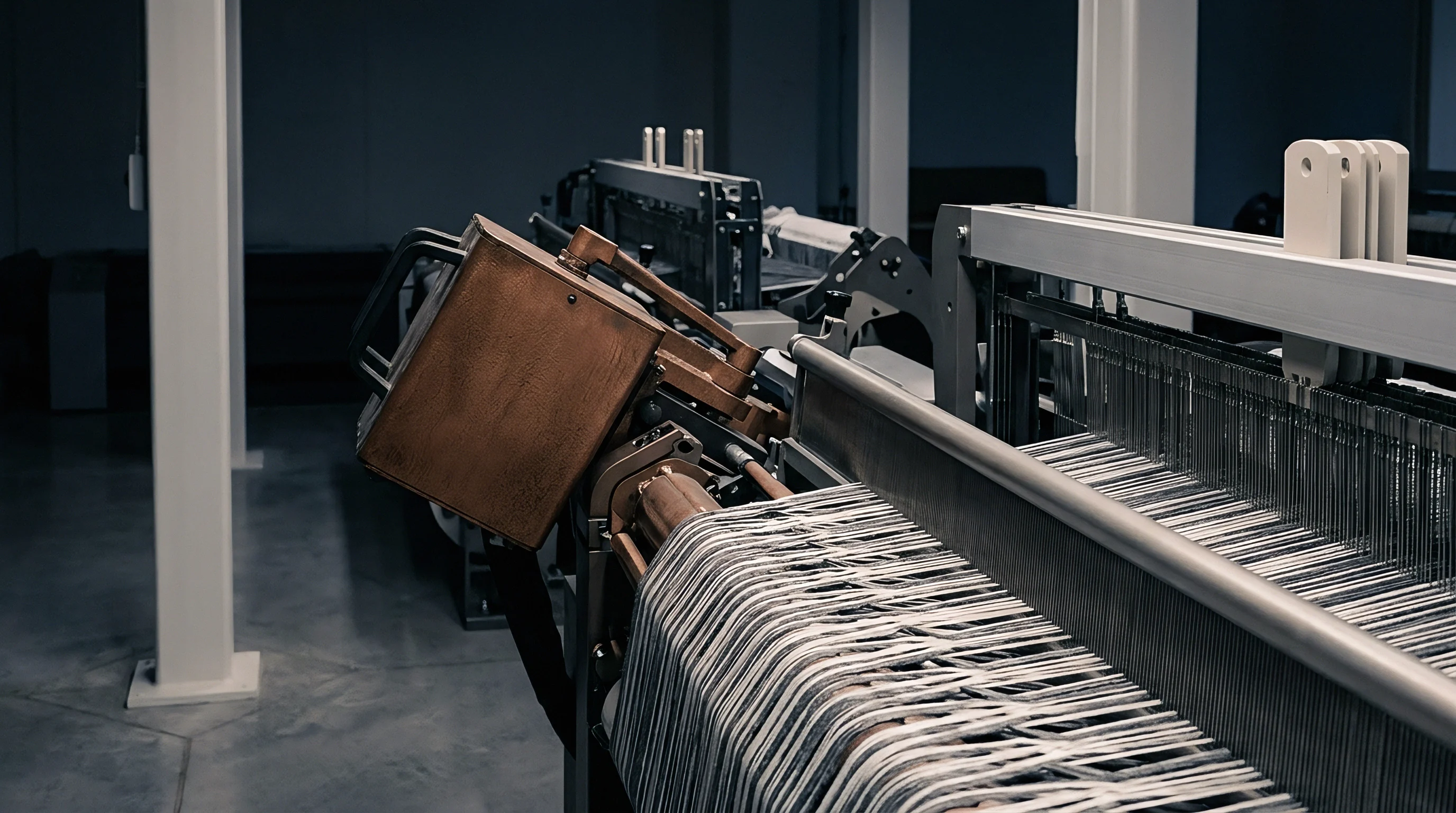
Pneumatic Waveforms and Dynamic Arrival Windows
Air pressure fluctuations inside the distributor manifold create secondary shockwaves during rapid speed shifts. Solenoid valves operating at 80 Hz experience thermal coil heating, shifting valve response time by up to 0.8 milliseconds over continuous production runs. This electronic lag disrupts the pneumatic wave pattern along the reed tunnel, generating localized low-pressure pockets.
Shed height restricts yarn passage. When the trailing pick tip passes through a pressure dip, axial tension drops, allowing the yarn core to relax prematurely before the reed beats up against the cloth fell. Loom operators who fail to synchronize pressure curves with dynamic drive acceleration face severe selvedge crimp imbalances and localized width variations across roll lengths.
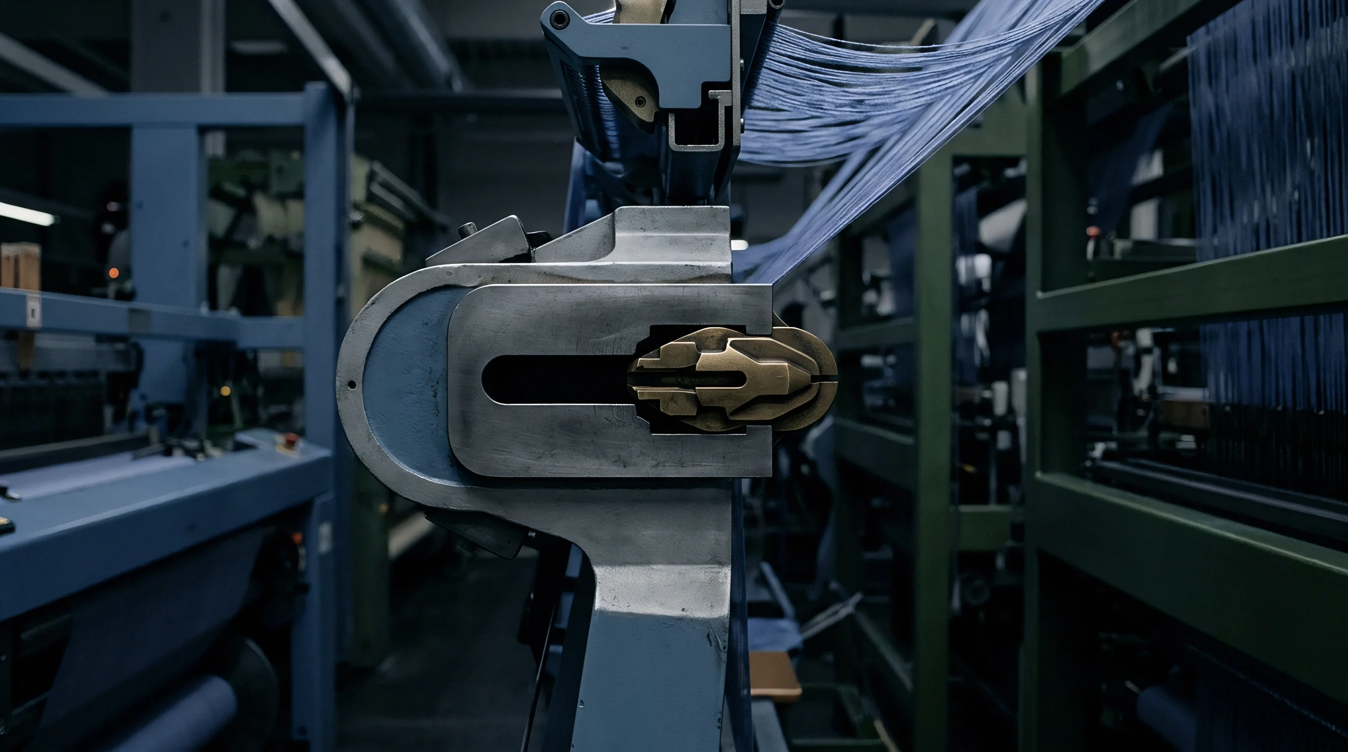
Drag
Aerodynamic interaction between the turbulent airflow and the yarn boundary layer forms the foundational driving force in air-jet insertion. The friction coefficient varies non-linearly with air velocity relative to the moving yarn substrate. High speed shortens insertion time.
Spun yarns with elevated hairiness exhibit significantly higher drag coefficients than smooth, fully-oriented continuous filament yarns. This surface friction creates an axial pulling force that scales with the square of the differential air speed, pulling micro-loops of fiber outward from the yarn core during propulsion.
Texturized filaments and ring-spun cotton yarns absorb pneumatic energy differently across dynamic speed shifts. A texturized polyester yarn compresses axially under high air velocity, reducing its effective surface profile while increasing density within the reed tunnel. Ring-spun cotton yarns expand under propulsion turbulence, causing high surface shear stress that converts directly into tension spikes.
These tension spikes induce transient elastic stretch along the pick path, which collapses into structural crimp once beat-up isolates the yarn from machine constraints.
Shed geometry influences boundary layer turbulence. When warp sheet clearance narrows during speed ramp-down, air escapes laterally through the upper and lower reed dents, diminishing the forward force vector. Yarn structures react to these fluid losses through distinct mechanical modes:
- Spun Staple Core Slippage occurs when dynamic air forces exceed internal fiber cohesion, shifting yarn twist distribution toward the receiving selvedge.
- Filament Micro-Loop Deceleration emerges in textured yarns as trailing filament loops catch cross-flowing air currents, inducing high-frequency axial chatter.
- Snarl Propagation develops in high-twist crepes when sudden drops in pneumatic drag permit live twist energy to loop the yarn back on itself before pick clamping.
- Selvedge Tail Snapback happens when extreme terminal air velocity stretches the trailing pick segment immediately prior to edge cutting.

Surface Roughness and Air Flow Boundary Dynamics
Frictional drag along the yarn perimeter increases under high nozzle pressure according to empirical boundary-layer fluid laws. Smooth continuous viscose filaments present minimal air resistance, requiring higher manifold pressures to achieve identical transport times compared to carded cotton. The pneumatic transfer efficiency drops as yarn velocity approaches air stream velocity, plateauing at a terminal acceleration curve.
Converters frequently attribute width unevenness to yarn package lot variations when the real root cause sits in uncompensated aerodynamic drag changes during loom speed ramping.

Reed
The structural geometry of the profile channel dictates air retention efficiency across the weaving width. Upper and lower tunnel ribs enclose the air jet, preventing rapid pressure dissipation into the open warp shed. Peak acceleration creates axial tension.
Shed closure timing governs the precise moment yarn movement ceases and warp end pressure locks the pick into place. Early shed closure catches the pick while still under forward transport momentum, forcing kinetic energy into the structural crimp of the weft yarn.
ISO 13934-1 breaking force and elongation requirements mandate that residual strain from pick insertion cannot exceed two percent of ultimate tensile capacity before shed closure.
Late shed closure allows the trailing end of the pick to relax and recoil inside the reed tunnel before warp cross-over locks the structure. This relaxation causes a drastic reduction in insertion tension, resulting in wide selvedge contraction off-loom. Measuring dynamic friction and tunnel losses across speed transitions requires a rigid protocol on the loom floor:
- Mount high-speed piezo-electric load cells at both the left-hand main nozzle side and right-hand receiving edge of the reed table.
- Calibrate pressure transducers inside the profile reed channel at 20-centimetre intervals across the total reed space.
- Execute loom speed steps from 600 RPM to 900 RPM in increments of 50 RPM while capturing continuous tension trace signals at 10 kHz sampling frequency.
- Record the precise crank angle of warp shed crossing using an optical shaft encoder synchronized with the main loom drive.
- Extract peak arrival tension spikes and isolate the post-braking relaxation decay curves for each speed plateau.

Interlock Geometry and Mechanical Friction
Warp thread density within the reed dent directly obstructs lateral air venting during shed movement. Heavy plain-weave constructions with cover factors above 22 compress the air column inside the reed channel, increasing localized air velocity near the channel floor. This compressed air boundary forces the weft yarn upward against the upper reed rib, introducing mechanical rubbing friction that acts against forward propulsion.
Equalizing warp sheet tension balances air dissipation across the top and bottom shed lines.
A loose warp tension setting reduces air channel confinement, causing early air release and pick instability.
Strain
Axial elongation during insertion is distributed unevenly along the pick length. The entry section near the main nozzle experiences sustained high tension during the entire flight duration. The middle section encounters cyclical tension pulses from relay nozzle passes.
Viscose filaments stretch under acceleration. The receiving tip experiences a sharp, high-magnitude impact shock when the mechanical weft brake engages to stop insertion at the right-hand edge.
This differential tension distribution induces non-linear viscoelastic strain across the fabric width. Upon loom off-loading, the yarn section subjected to the highest strain undergoes greater elastic recovery, pulling the fabric edges inward relative to the fabric center. The resulting off-loom width contraction profile shows an asymmetrical curve, with peak contraction localized within the final third of the reed space.

How Does Loom Speed Variance Shift Crimp Contraction?
Loom speed directly dictates the rate of kinetic energy dissipation at weft braking. Operating the main shaft at higher speeds reduces the time available for stress relaxation while the pick remains held under tension in the closed shed. The yarn retains high internal stress when cut at the selvedge, causing instant recoil upon release from the temple cutters.
Crimp energy stores inside warp.
Higher insertion speeds exaggerate the tension gradient between the insertion side and the receiving side of the loom shed.
Testing weft crimp variation across the grey fabric roll requires systematic sampling across three designated width zones: Right-Hand Side (RHS), Center (CTR), and Left-Hand Side (LHS). Crimp percentage is calculated using ISO 7211-3 methods where removed yarn length is compared against straight fabric length under standard tensioning weights.
| Fibre Type & Count | Loom Speed (RPM) | RHS Crimp (%) | CTR Crimp (%) | LHS Crimp (%) | Total Off-Loom Contraction (%) |
|---|---|---|---|---|---|
| 100% Cotton 20 tex | 650 | 7.2 | 8.5 | 7.8 | 4.8 |
| 100% Cotton 20 tex | 850 | 6.8 | 8.6 | 8.9 | 6.2 |
| 100% Cotton 20 tex | 1000 | 6.1 | 8.7 | 10.2 | 7.9 |
| Polyester 150d / 48f | 650 | 5.1 | 6.2 | 5.8 | 3.9 |
| Polyester 150d / 48f | 850 | 4.8 | 6.3 | 7.1 | 5.1 |
| Polyester 150d / 48f | 1000 | 4.2 | 6.4 | 8.6 | 6.8 |
Worked Calculation of Viscoelastic Recoil Profile
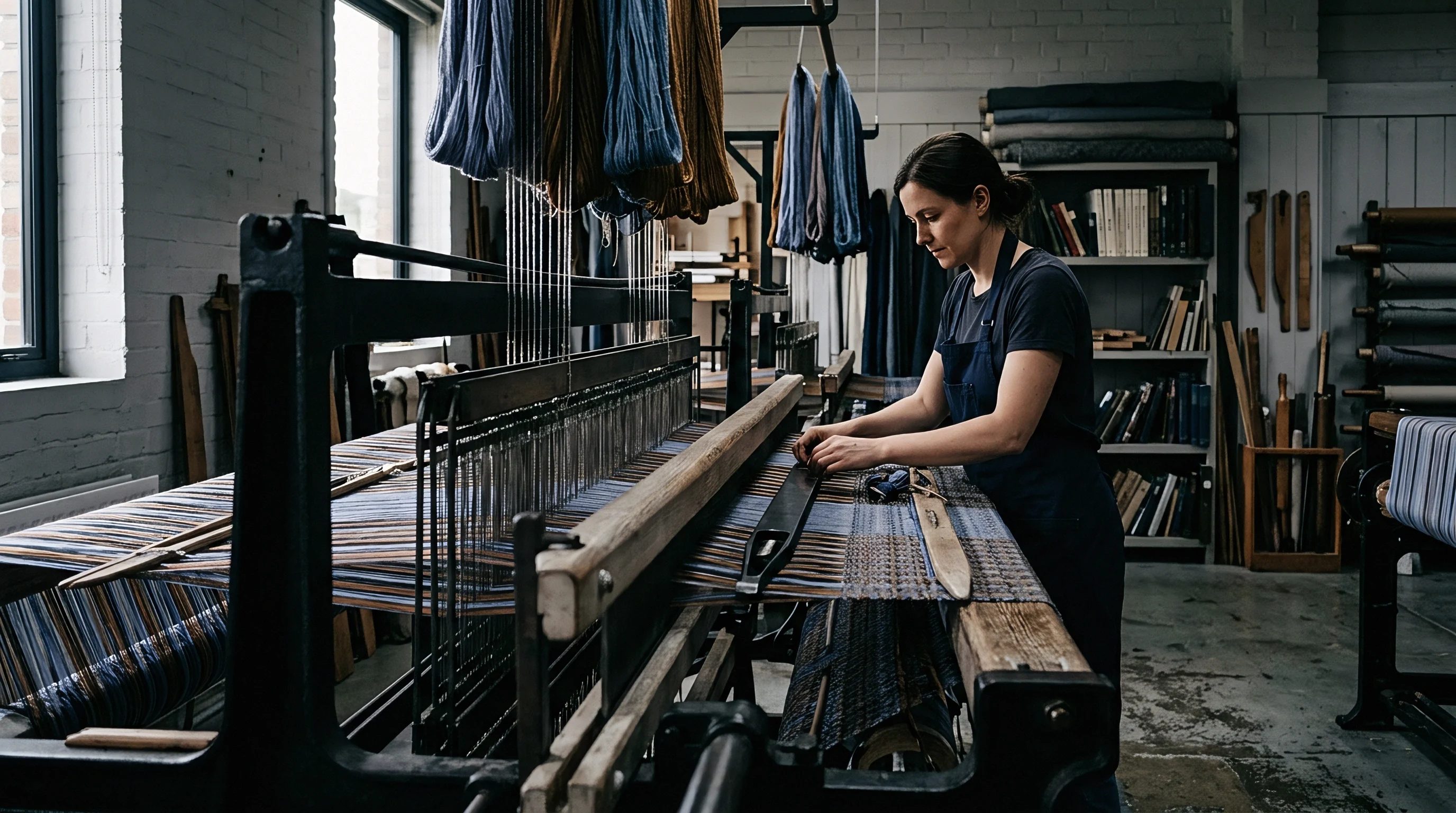
Consider a 190-centimetre reed width weaving a 100% spun viscose yarn of 19.5 tex at two distinct speed profiles. Assume a baseline speed of 700 RPM generating a terminal pick tension of 35 cN at the brake, resulting in a uniform 1.8% elastic stretch prior to shed closure. Off-loom relaxation yields a linear width contraction of 3.42 centimetres, leaving a grey width of 186.58 centimetres.
Now increase machine speed to 950 RPM without modifying pneumatics. Impact tension at the brake jumps to 58 cN on the receiving side (LHS), while entry tension (RHS) remains at 38 cN. The localized elastic stretch reaches 3.8% across the final 50 centimetres of the pick, 2.2% across the center, and 1.9% at the entry.
The integrated viscoelastic strain across the full width averages 2.63%. The resulting grey width contracts by 5.00 centimetres down to 185.00 centimetres. The edge-to-center crimp delta widens from 0.4% at low speed to 2.4% at high speed, creating longitudinal fabric waviness that cannot be flattened during stenter finishing without introducing skew.
Does the asymmetrical contraction stabilize after ambient conditioning, or does humidity exposure in wet processing trigger further latent stress relaxation?

Brake
Mechanical weft leaf brakes engage at the end of the insertion arc to absorb yarn velocity before shed clamping. Braking timing must adjust dynamically with shaft acceleration to maintain a constant deceleration force profile. Engaging the brake too early causes pick bounce, where the yarn recoils into the open shed and forms slack loops.
Engaging the brake too late slams the yarn tip against the retaining pin, generating extreme tension spikes that permanently deform the polymer structure.
Electronically controlled programmable weft brakes utilize stepped pneumatic or magnetic resistance pads to apply progressive deceleration. Stepping the braking force over three distinct angles reduces peak impact force by up to 40 percent. Solenoid response limits speed shifts.
Aligning braking curves with variable loom speeds prevents localized necking of synthetic filaments and preserves uniform yarn diameter across the entire cloth width.
Managing braking programs across variable speed production orders involves strict machine setup choices:
- Speed-Proportional Pressure Stepping modulates brake pad clamping force dynamically based on real-time main shaft encoder feedback.
- Deceleration Angle Advance shifts the trigger point of the mechanical brake earlier in the cycle as shaft RPM increases.
- Relay Nozzle Overlap Reduction cuts trailing relay group airflow 3 milliseconds prior to brake engagement to drop forward momentum.
- Active Drop-Pin Damping absorbs the terminal vibration of the yarn tip using spring-loaded guide pins situated past the receiving selvedge.
Pneumatic Compensation and Braking Mechanics
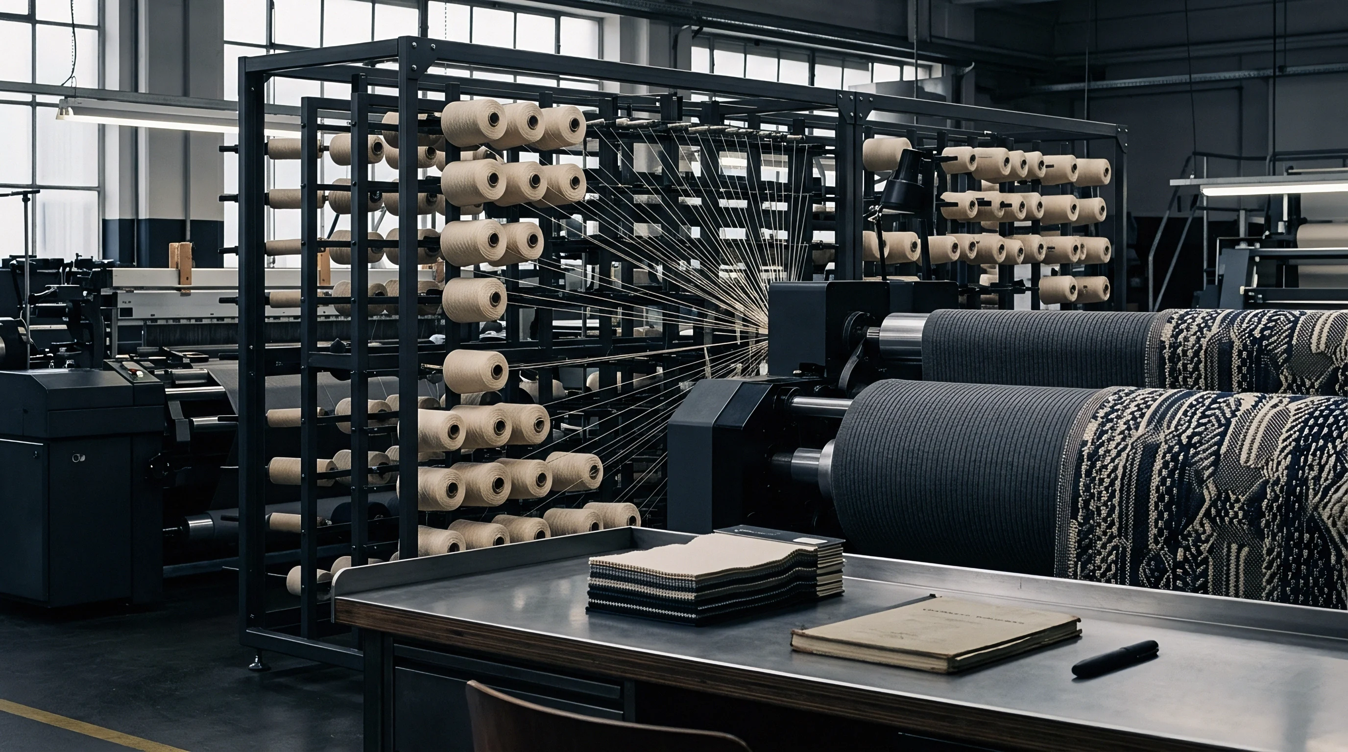
Modulating main nozzle pressure simultaneously with brake activation softens the final impact force. If the main nozzle continues firing at full pressure while the weft brake clamps the yarn, severe axial shear forces concentrate within the first 10 centimetres of the pick length. Warp tension balances weft contraction.
Reducing main nozzle line pressure by 0.08 megapascals exactly 15 crank degrees before brake engagement eliminates early-stage tension peaks.
According to standard commercial purchase conditions referencing ISO 3939 woven fabric construction specs, off-loom width variance across a single production lot must remain within plus or minus 0.75 percent of the nominal target width, or the buyer retains the right to reject the entire batch at the mill gate.


Ledge
Predicting final fabric width requires a unified model that balances reed space allowance, dynamic weft strain, warp cover factor, and finishing machine overfeed adjustments. Off-loom grey width serves as the baseline for all subsequent wet processing calculations. Reed width exceeds finished width.
When air-jet looms run variable speed profiles without continuous tension correction, off-loom grey width fluctuates from roll to roll, forcing finishing plant operators to constantly adjust stenter width rails to avoid selvedge tears.
| Target Finished Width (cm) | Nominal Reed Space (cm) | Loom Operational Speed (RPM) | Grey Off-Loom Width (cm) | Finishing Stenter Overfeed (%) | Landed Fabric Yield (m/m) |
|---|---|---|---|---|---|
| 150 | 162 | 650 (Static) | 154.5 | +2.5 | 0.953 |
| 150 | 162 | 850 (Static) | 153.2 | +3.8 | 0.945 |
| 150 | 162 | 700-950 (Dynamic) | 151.8 | +5.2 | 0.937 |
| 280 | 302 | 600 (Static) | 288.4 | +2.0 | 0.955 |
| 280 | 302 | 800 (Static) | 286.1 | +3.2 | 0.947 |
| 280 | 302 | 600-850 (Dynamic) | 283.5 | +4.8 | 0.938 |
Finishing Interventions and Yield Arithmetic
Excessive grey width contraction forces the finishing house to pull the cloth wide under high heat-setting tensions to reach customer target specs. Over-stretching fabric in the stenter frame increases residual dimensional instability, causing finished garments to shrink excessively during domestic laundering. Overfeed balances off-loom grey shrinkage.
When a 100% cotton poplin suffers an unaccounted 2.5% increase in weft contraction due to uncompensated high-speed weaving strain, the stenter operator must apply extra longitudinal overfeed to balance square metre weight requirements.
This adjustment alters the total linear yield per loom production hour. A weaver running 50 air-jet looms at 900 RPM with uncorrected speed profiles loses up to 1.8 centimetres of usable width across every roll. Across a 100,000-metre contract, that lost width equates to 1,800 square metres of unsellable trim waste, converting directly into lower operating margins and higher cost per finished metre.
Width variation along a single roll of cloth reflects uncontrolled pressure stepping during machine speed transitions.
Calculations for total landed cost must account for the additional yarn weight needed to fill out a narrow grey roll. If the weft yarn contracts beyond predicted boundaries, warp end density increases per centimetre, lifting fabric mass per unit area above specified upper tolerances. The buyer pays for excess raw material consumed to yield narrower usable goods.
Automated closed-loop pneumatic control systems linked to loom shaft encoders mitigate these contraction dynamic shifts at the point of insertion, locking grey width stability before the cloth winds onto the batcher roll.