Knitting Machine Gauge Optimization for Controlled Aqueous Loop Contraction
Matching knitting machine gauge to yarn linear density fixes loop tightness factor, setting the upper limit for aqueous dimensional contraction during wet finishing.
Pitch
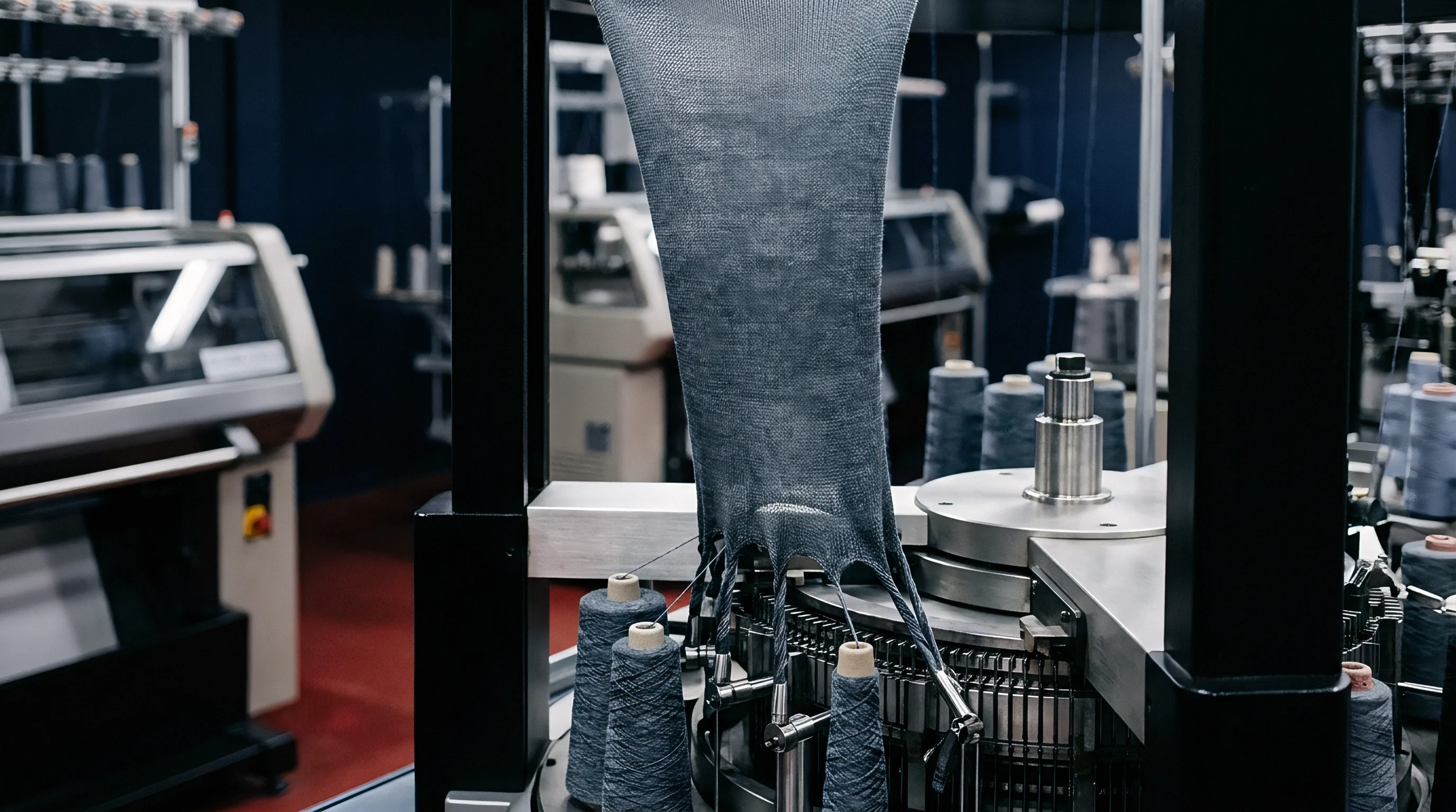
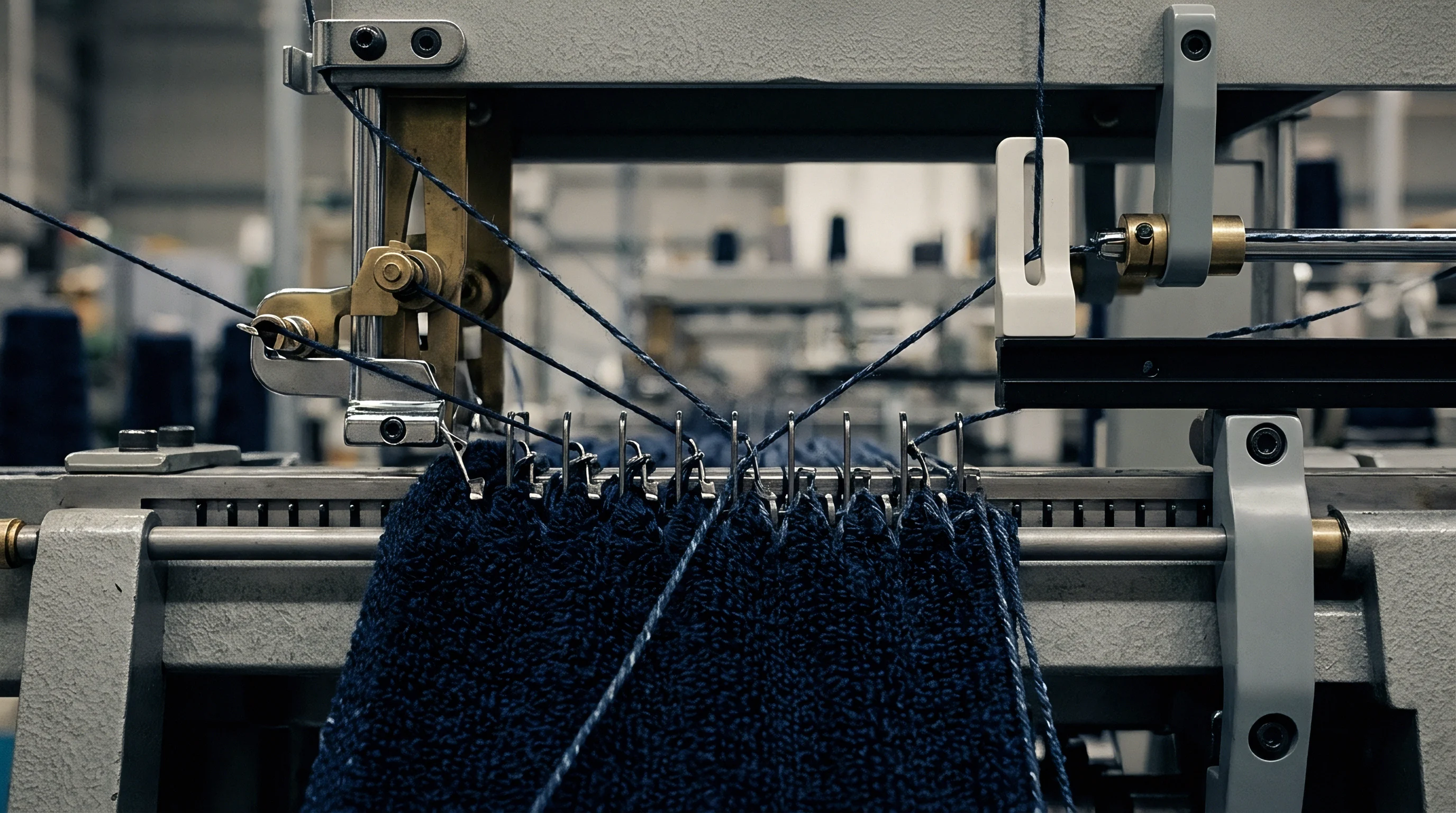
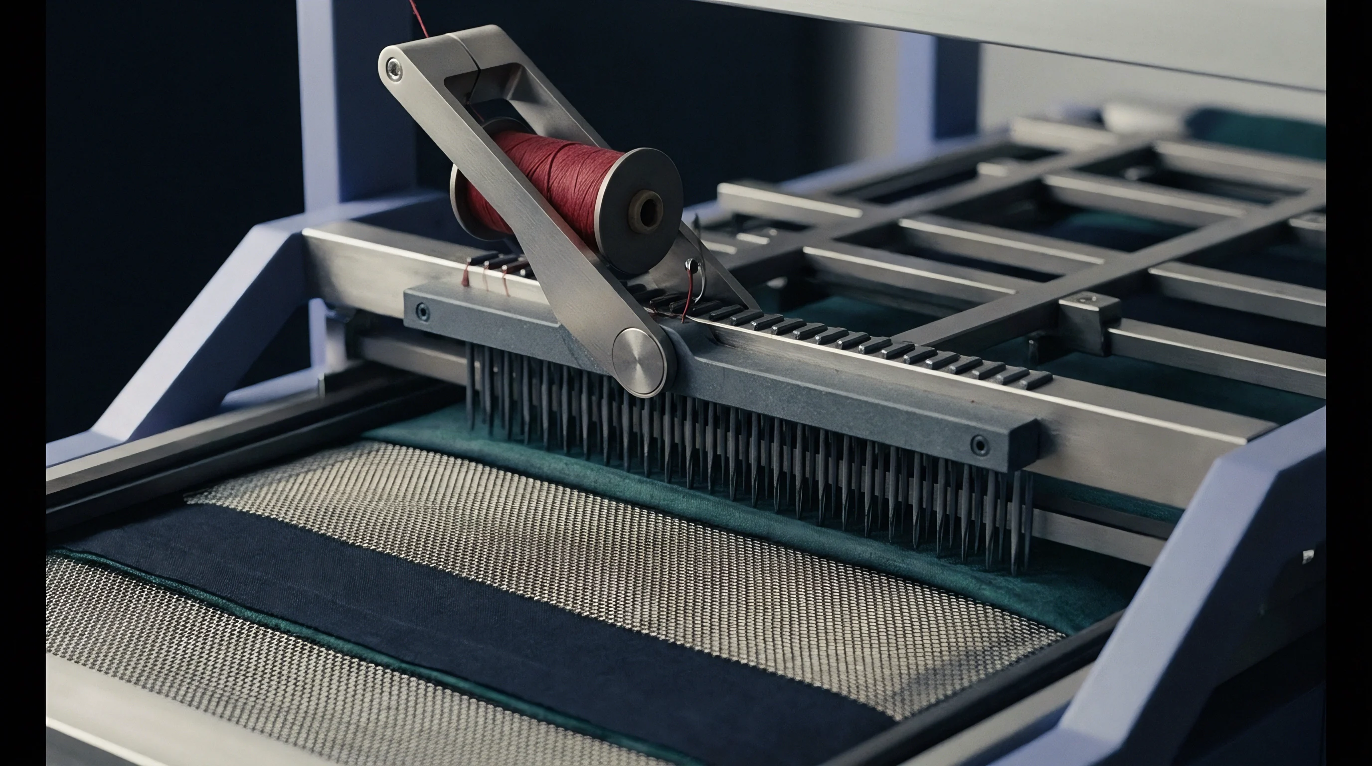
The distance between adjacent needles on a circular knitting cylinder defines the space available for loop formation. As the cylinder rotates, latch needles move vertically inside cut tricks, guided by stationary cam tracks. The angular drop of the stitch cam draws the needle down, pulling the newly laid yarn across the sinker belly to form a loop.
Trick spacing restricts the maximum yarn diameter that can pass without generating excessive inter-yarn friction. When yarn linear density exceeds the geometric envelope of the needle gate, the clearing latch strikes adjacent yarns, causing mechanical abrasion before the loop is even cast off.
Dynamic loop-forming forces fluctuate rapidly as the needle reaches the lowest point of its stroke. A steeper cam angle accelerates needle descent, raising peak tension on the incoming yarn strand. This force stretches the newly formed loop past its equilibrium dimensions while the yarn is still held under mechanical restraint.
Sinker timing controls when the old loop clears the latch as the new loop forms. Advancing or delaying that timing changes how much yarn is pulled from the adjacent needle loop versus directly from the supply package feed cone. When feed tension is uneven, stitch length variations propagate across adjacent wales, creating structural irregularities that stay hidden until wet processing.
Needle Gate Geometry and Loop Formation Mechanics
The trick pitch on a circular knitting machine determines the gate width available to yarn during stitch formation. Needles move in parallel slots around the cylinder, separated by steel trick walls. Center-to-center spacing between adjacent slots sets this circumferential pitch.
As machine cut increases, space tightens, calling for thinner needle hooks and thinner walls. High-speed knitting forces yarn through the narrow gap between hook and sinker nib. If the yarn cross-section contains thick places or slubs wider than that clearance, the yarn shears inside the needle gate.
Knitting cylinder gauge sets the upper limit for yarn linear density. Forcing heavy yarn counts into fine needle tricks compresses the yarn inside the loop head. That compressed yarn exerts high lateral pressure against the hook interior, accelerating latch wear and causing random hook breakage.
Conversely, running overly fine yarns on coarse gauges leaves wide gaps between adjacent loops. Coarse spacing lets yarn float loosely across the sinker belly, resulting in poor structural stability in the raw greige state.
Cam Profile Angle and Dynamic Tension Spikes
Stitch cams govern the vertical trajectory of needle butts passing through the cam box. The downward gradient on the stitch cam dictates needle velocity during loop drawing. Steep angles shorten the mechanical profile of the feeder section, allowing more feeds around the cylinder.
However, rapid needle acceleration creates sharp tension spikes at the knitting point. Peak force concentrated on the loop head can exceed the yarn’s elastic yield limit, causing permanent elongation in the raw loop before the fabric leaves the cylinder.
- Latch Wire Jamming occurs when heavy yarn counts expand beyond the needle hook slot, causing the latch to hit yarn fibers as it closes and creating broken filaments across the fabric face.
- Loop Length Variation arises from unequal stitch cam depth settings across feeds, leading to alternating course densities that show up as horizontal banding after aqueous relaxation.
- Sinker Nib Wear develops when abrasive spun yarns are drawn under high dynamic tension over the sinker throat, carving grooves into the steel edge that snag subsequent loops.
- Spirality Inception initiates when steep cam profiles introduce unbalanced torque into spun yarns during high-speed loop casting, tilting wales away from the vertical axis.
Running circular knitting machinery with bad gauge-to-yarn pairings compromises structural integrity well before wet finishing begins. Fabric knitted under high dynamic tension spikes retains internal stress, leading to severe needle-line defects, frequent yarn breaks on the machine, and uneven greige yield that no amount of downstream stenter processing can correct.

Swell
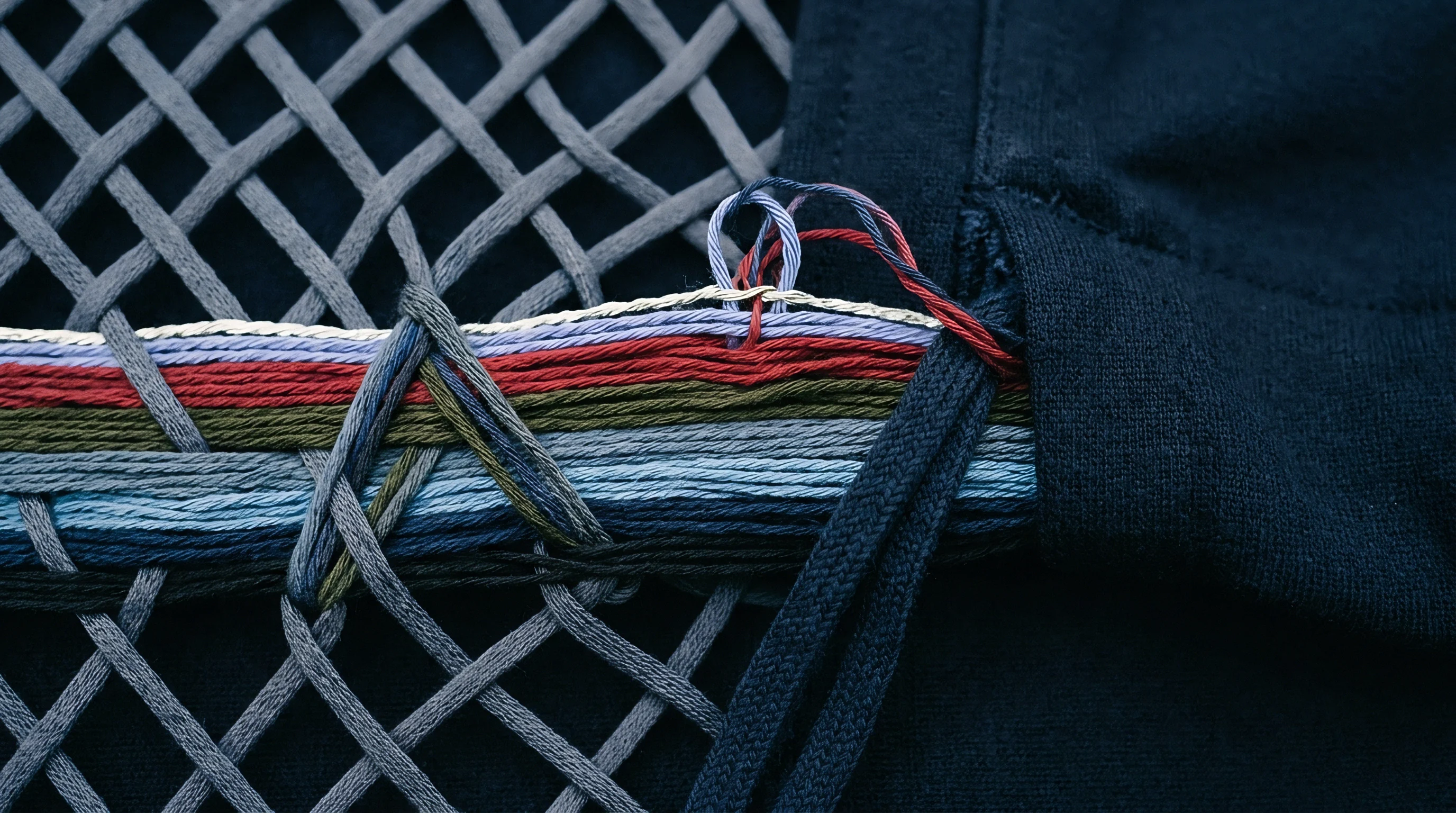
Immersing spun cellulosic yarn in an aqueous bath triggers rapid water absorption into the amorphous regions of the cotton fiber matrix. Water molecules break internal secondary hydrogen bonds, pushing adjacent cellulose polymer chains apart. This displacement expands individual fibers significantly in cross-sectional diameter with negligible growth along their longitudinal axis.
As fibers expand, total yarn diameter increases across the loop matrix. This physical enlargement forces loop geometry to alter its curvature, accommodating the thicker strand within a fixed loop length.
Aqueous yarn expansion reduces the open space inside each knitted loop. Because the yarn length allocated to each stitch is fixed once knitted, radial growth forces the loop head and feet to curve more sharply. This pronounced bending pulls adjacent courses and wales closer together, driving macro-level fabric contraction in both length and width.
How much fabric shrinks during wet finishing depends on how freely the loop structure can reconfigure around the swollen yarn diameter before reaching mechanical yarn-on-yarn jamming.

Cellulosic Hydration and Radial Yarn Expansion Mechanics
Water penetration into cotton yarn triggers radial dimensional changes dictated by fiber structure. Raw cotton fibers have a bean-shaped cross-section when dry. Upon hydration, the internal lumen fills with fluid and cell walls expand outward, rounding out the profile.
Radial diameter increases by fourteen to twenty percent, while axial length grows by less than one percent. Ring-spun, compact-spun, and open-end rotor yarns show distinct swelling behaviors because of differences in fiber arrangement and twist distribution.
Single jersey cotton fabrics knitted to a tightness factor below 1.25 experience length contraction exceeding sixteen percent when exposed to unconstrained aqueous washing at sixty degrees Celsius.
Ring-spun yarns carry surface fibers wrapped at defined helix angles. When core fibers swell radially, these surface wraps contract along the yarn axis, shortening effective yarn length and pulling loop heads tighter against the sinker loops. Open-end yarns contain random wrapper fibers that restrict uniform radial expansion, creating localized swelling that frictionally locks contact points early in hydration.
Compact-spun yarns, with their uniform fiber orientation and low hairiness, permit clean geometric shifting of the loop structure during aqueous exposure, yielding highly predictable dimensional contraction.

Three Dimensional Loop Curvature and Munden Constants
Dimensional behavior in knitted structures follows established loop geometry models. Munden relationships define course density, wale density, stitch density, and loop shape factor as inverse functions of knitted stitch length. These constants describe fabric across three relaxation environments: dry relaxed, wet relaxed, and fully tumble-dried.
As fabric moves from off-machine to a fully relaxed state, the Munden constants shift systematically, reflecting the loop’s adjustment toward its minimum energy configuration.
| Fabric Construction | Relaxation State | Course Constant (kc) | Wale Constant (kw) | Stitch Density Constant (ks) | Aspect Ratio (kr) |
|---|---|---|---|---|---|
| Single Jersey | Dry Relaxed | 5.0 | 3.8 | 19.0 | 1.32 |
| Single Jersey | Wet Relaxed | 5.3 | 4.1 | 21.7 | 1.29 |
| Single Jersey | Fully Tumble Dried | 6.0 | 4.3 | 25.8 | 1.40 |
| 1×1 Rib | Dry Relaxed | 5.3 | 3.2 | 17.0 | 1.66 |
| 1×1 Rib | Fully Tumble Dried | 6.7 | 3.8 | 25.5 | 1.76 |
| Interlock | Dry Relaxed | 5.4 | 3.7 | 20.0 | 1.46 |
| Interlock | Fully Tumble Dried | 6.7 | 4.1 | 27.5 | 1.63 |
| Data measured on combed cotton yarns ranging from 20 Tex to 30 Tex across machine gauges 20G through 28G following ISO 5077 relaxation procedures. | |||||
Dry relaxation allows partial elastic recovery of mechanical strains introduced during knitting, but it cannot relieve locked-in yarn torque. Wet relaxation breaks hydrogen bonds within the fiber matrix, permitting loops to twist out of their flat plane into a three-dimensional configuration. Full tumble drying introduces mechanical action and heat, letting swollen yarns slide completely to a minimum-energy equilibrium where course and wale constants reach stable maximums.
Mill management often blames persistent garment shrinkage on chemical finishing failures at the stenter frame. In practice, wet processing lines cannot override physical loop jamming boundaries set when machine gauge and stitch length were chosen back on the knitting floor.

Tension
Calculating stitch length requires measuring the unraveled thread distance across a fixed course count. Stitch length, combined with yarn linear density, defines the tightness factor ~ the relative area of the loop covered by yarn versus open space. If the tightness factor is set too low, the open structure shifts widely during aqueous processing.
If set too high, yarn strands press against each other inside loop heads, reaching a jam point where internal friction prevents further contraction.
Contractual specifications following ISO 5077 mandate that bulk production lots must stay within a plus or minus three percent threshold for finished course density against approved reference standards.
Jamming sets an absolute physical limit on loop movement. When yarn swells within an over-tightened loop structure, transverse forces at crossover points rise exponentially. The fabric stiffens drastically, developing a harsh hand and elevated surface abrasion during jet dyeing.
Optimizing machine gauge requires adjusting stitch length so that the fully relaxed, post-wash loop configuration sits comfortably below the jam point while keeping shrinkage within commercial tolerances.
Tightness Factor Boundaries and Structural Jamming
Fabric tightness factor relies on metric loop length and yarn linear density, expressed as the square root of yarn Tex divided by stitch length in millimeters. Single jersey fabrics typically operate between 1.10 and 1.60 Tex^0.5 / mm. Operating below 1.20 creates a slack structure prone to heavy washing shrinkage and torque-induced spirality, while going above 1.50 pushes the yarn toward physical jamming.
| Machine Gauge (E) | Trick Pitch (mm) | Yarn Count Range (Ne) | Yarn Linear Density (Tex) | Optimum Stitch Length (mm) | Target Tightness Factor |
|---|---|---|---|---|---|
| 18 G | 1.411 | 12/1 – 18/1 | 49.2 – 32.8 | 3.80 – 4.20 | 1.36 – 1.45 |
| 24 G | 1.058 | 24/1 – 32/1 | 24.6 – 18.5 | 2.80 – 3.10 | 1.38 – 1.48 |
| 28 G | 0.907 | 30/1 – 40/1 | 19.7 – 14.8 | 2.50 – 2.80 | 1.37 – 1.46 |
| 32 G | 0.794 | 40/1 – 50/1 | 14.8 – 11.8 | 2.20 – 2.50 | 1.38 – 1.45 |
| 36 G | 0.706 | 50/1 – 60/1 | 11.8 – 9.8 | 1.95 – 2.20 | 1.39 – 1.47 |
Structural jamming occurs when the space occupied by yarn cross-sections equals the interior dimensions of the loop. At this boundary, Pierce’s geometric model dictates that loop legs touch laterally while the loop head squeezes the feet of the preceding stitch. Additional contraction cannot occur without deforming the circular cross-section of the yarn into an elliptical shape under high compressive force.
The table parameters outline the operational window needed to achieve balanced physical performance without risking jamming during wet finishing.

Gauge Selection across Yarn Linear Densities
Matching yarn count to machine gauge preserves structural mobility inside the loop matrix. Selecting an improper gauge forces knitters to manipulate stitch length outside safe geometric limits just to reach target fabric weight.
- Target Shrinkage Evaluation verifies that the calculated tightness factor leaves sufficient geometric clearance for post-wash loop contraction.
- Linear Density Verification confirms that actual yarn Tex matches the nominal yarn count within a two percent tolerance before setting stitch cams.
- Trick Spacing Clearance checks that the maximum yarn diameter does not exceed thirty-five percent of the needle trick width.
- Torque Balance Assessment calculates the residual single-yarn twist multiplier to prevent excessive loop rotation in slack-knitted constructions.
Single jersey loop stability improves as tightness factor approaches 1.45, provided the wet processing plant avoids stretching fabric along the wale axis during drying.
Relaxation
Mechanical strain accumulated during high-speed loop formation stays locked inside the yarn grid through inter-fiber friction. When greige fabric enters wet processing, aqueous flotation, heat, and mechanical agitation release this stored energy. Water softens the fiber surface, lowering static friction.
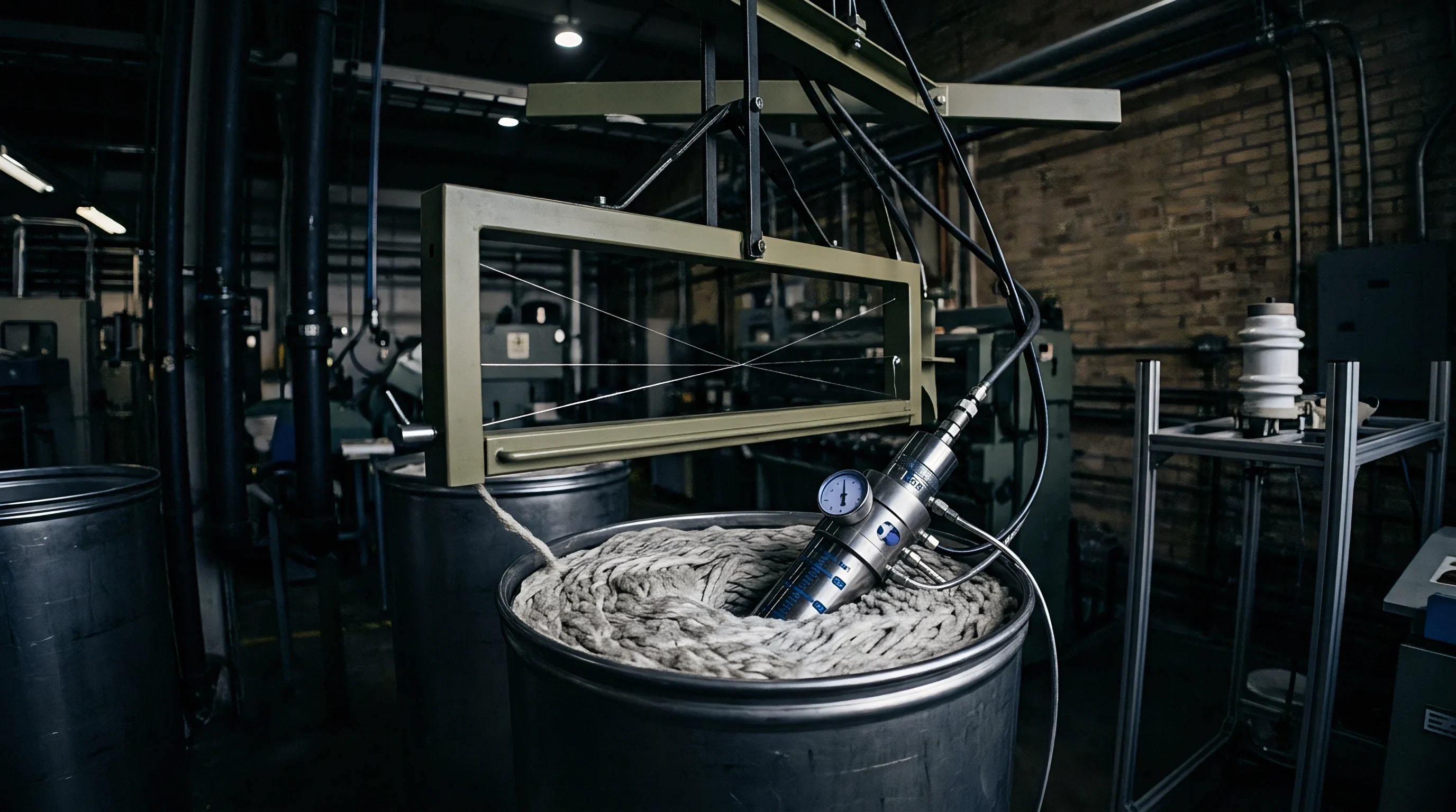
As jet nozzles introduce axial tension while circulating the fabric rope through the transport tube of a jet dyeing vessel, continuous hydraulic impacts compress the fabric along its length, driving loop relaxation.
Hydrodynamic forces inside the jet vessel allow loops to contract radially and lengthways without external mechanical constraint. Fluid turbulence folds and flexes the fabric rope, breaking localized mechanical bridges between adjacent courses before compactor shoes compress course spacing in finishing. This hydrodynamic agitation allows individual loops to slide past one another until reaching their natural, unconstrained dimensions.
If fabric is held under high longitudinal tension during continuous washing or open-width bleaching, loops stay elongated along the wale direction, leaving residual contraction energy that manifests as severe washing shrinkage in the finished garment.

Hydrodynamic Mechanical Strain Relief in Jet Dyeing
A jet dyeing machine acts as both a chemical reaction vessel and a mechanical relaxation system. Nozzle pressure creates a high-velocity fluid stream that propels the fabric rope through the venturi tube. This hydraulic action exerts alternating forces on the knitted structure ~ sudden acceleration inside the nozzle followed by immediate deceleration and accumulation in the liquor holding chamber.
As fabric folds into the chamber, the sudden impact compresses courses together, relieving longitudinal tension.
Mechanical compaction overfeeds fabric onto a heated cylinder, mechanically driving courses closer together to lock in pre-wash dimensional stability.
Controlling vessel speed, nozzle aperture size, and liquor ratio regulates loop relaxation rate. A low liquor ratio increases fiber-to-fabric friction, accelerating strain recovery but raising the risk of surface pilling and rope marks on delicate cotton structures. Proper nozzle pressure maintains continuous rope motion without excessive longitudinal stretching.
Winch reel mechanical squeezing must be balanced against nozzle transport speed to prevent re-stretching relaxed loops before heat setting or tumble drying.
Stenter Overfeed and Mechanical Compaction Dynamics
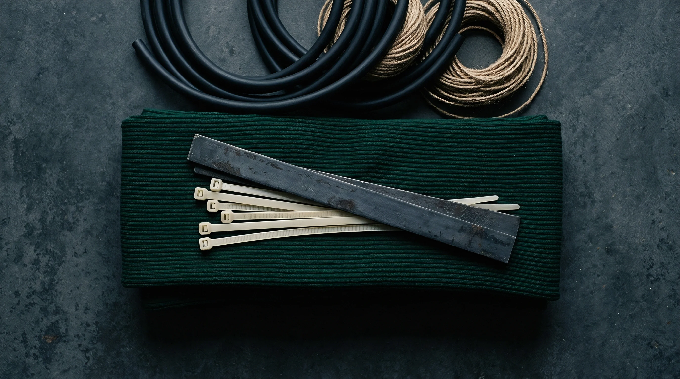
Drying relaxed fabric on a pin stenter frame establishes its final open-width dimensional profile. The overfeed system feeds fabric onto the stenter chain pins faster than the chain is moving. This speed differential forces excess fabric length onto the pins, creating microscopic ripples along the selvedges that pull flat as the fabric dries, while stenter pins carry the border loads.
Overfeeding allows loops to contract along the wale direction inside the drying chamber, setting target finished courses per centimeter.
- Aqueous Impregnation saturates the greige fabric with water and wetting agents in a pad trough to disrupt inter-fiber hydrogen bonds and initialize stress recovery.
- Hydrodynamic Jet Agitation subjects the fabric rope to continuous hydraulic impact inside a jet dyeing vessel, releasing locked knitting tensions.
- Open Width Dewatering passes the relaxed web through a soft-nip squeezer or vacuum extractor to remove free water while minimizing longitudinal tension.
- Stenter Overfeed Drying applies twelve to thirty percent longitudinal overfeed during hot air passage, allowing course density to settle into equilibrium.
- Rotary Mechanical Compaction feeds the dry fabric between a rubber belt and heated steel cylinder, physically compacting the loop structure to seal post-wash stability.
Standard purchase agreements require compliance with ISO 6330 test methods for domestic washing and drying, specifying that finished fabric dimensional change must not exceed five percent in either course or wale directions after three consecutive wash cycles.


Arithmetic
Quantitative fabric design bridges raw mechanical settings and finished yield expectations. Engineering a 200 GSM finished combed cotton single jersey fabric with less than five percent post-wash shrinkage requires solving machine gauge, yarn linear density, and stitch length as a single system. Assuming a combed cotton yarn of 30/1 Ne (19.7 Tex), the design evaluates gauge options across 24G and 28G setups.
The target relaxed state requires a final stitch density (S) derived from the Munden fully relaxed constant (ks = 25.8).
Determining target stitch length requires balancing wet contraction yield against mechanical knittability. On a 28G machine with a 0.907 mm trick pitch, an optimized stitch length of 2.65 mm yields an off-machine tightness factor of 1.44 Tex^0.5 / mm. During wet processing and compaction, the fabric contracts along courses and wales, shifting course density from an off-machine 14 courses per cm to a finished relaxed 21 courses per cm.
Corresponding wale density moves from 11.5 to 14.2 wales per cm.
Engineering a Finished Fabric Weight Specification
Calculating finished fabric weight per unit area relies on the relationship between yarn Tex, course density, wale density, and stitch length. Weight in grams per square meter equals the product of stitch length in millimeters, yarn Tex, and stitch density in stitches per square centimeter, divided by one hundred. Using the optimized 2.65 mm stitch length with 19.7 Tex yarn at a relaxed stitch density of 298.2 stitches per square cm (21 courses/cm x 14.2 wales/cm), the calculated finished dry weight reaches 202.8 GSM.
| Parameter | Option A (24 Gauge) | Option B (28 Gauge) | Option C (32 Gauge) |
|---|---|---|---|
| Yarn Linear Density (Ne / Tex) | 24/1 Ne (24.6 Tex) | 30/1 Ne (19.7 Tex) | 36/1 Ne (16.4 Tex) |
| Stitch Length (mm) | 2.95 mm | 2.65 mm | 2.40 mm |
| Tightness Factor (Tex^0.5 / mm) | 1.68 (Jammed) | 1.44 (Optimal) | 1.28 (Slack) |
| Greige Course Density (courses/cm) | 12.0 | 14.0 | 16.5 |
| Finished Relaxed Course Density (courses/cm) | 18.0 | 21.0 | 24.5 |
| Finished Relaxed Wale Density (wales/cm) | 12.5 | 14.2 | 16.0 |
| Calculated Finished Weight (GSM) | 223.5 GSM | 202.8 GSM | 182.2 GSM |
| Washing Shrinkage ISO 6330 (Wale %) | -2.1 % | -4.2 % | -11.8 % |
| Fabric Yield (Finished Metres / Tonne at 180cm width) | 2,485 m | 2,738 m | 3,047 m |
The comparative data highlights these structural trade-offs. Option A uses yarn too coarse for 24G, pushing tightness factor to 1.68, which leads to yarn jamming, over-weight fabric (223.5 GSM), and low meterage yield per tonne. Option C uses an overly fine yarn on 32G with a low tightness factor of 1.28, creating an open, slack structure that suffers an unacceptable 11.8 percent length shrinkage in testing.
Option B delivers the target 200 GSM weight while keeping shrinkage securely under five percent.

Yield and Shrinkage Trade Offs across Machine Gauges
Evaluating commercial fabric yield requires converting yarn consumption into usable linear meters of finished fabric at a specified cuttable width. Over-stretching fabric on the stenter to boost linear yield reduces weight per meter, but increases post-wash shrinkage in direct proportion to the applied strain.
Stitch length setting determines final finished fabric mass more directly than stenter overfeed adjustments.
- Extract a minimum of five full-width fabric swatches across the length of the dye lot roll, ensuring sampling takes place at least three meters away from roll ends.
- Condition all specimens in a standard atmosphere at twenty degrees Celsius and sixty-five percent relative humidity for twenty-four hours according to ISO 139.
- Mark a 300 mm by 300 mm square benchmark grid on each specimen using indelible fine-tip textile markers aligned precisely along individual wales and courses.
- Process the specimens through three continuous wash cycles in an ISO 6330 front-loading horizontal drum washer at forty degrees Celsius using non-phosphate standard detergent.
- Tumble dry the specimens in a exhaust dryer until completely dry, allow them to condition for four hours, and measure dimensional changes across marked benchmarks to calculate percentage contraction.
Higher bath temperatures accelerate hydrogen bond turnover, enabling maximum geometric loop compaction inside the vessel.
Allowance
Commercial fabric specifications establish permissible variations for finished mass and dimensional change. Standard supply contracts mandate a weight tolerance of plus or minus five percent from the approved sample target. Width specifications generally allow zero to plus two centimeters on cuttable width.
When a mill stretches fabric to hit width targets without optimizing underlying loop geometry on the knitting machine, the fabric fails post-wash dimensional stability tests during buyer audits.
Financial liability for non-conforming fabric rests on verified laboratory compliance records. Sourcing contracts include penalty clauses for dimensional failure, specifying chargebacks or lot rejections if washing shrinkage exceeds target thresholds. If a mill knits fabric overly tight to pass shrinkage tests, overall linear yield per tonne of yarn drops, raising landed cost per finished meter.
Sourcing audits should verify machine gauge, yarn count, and stitch length at the knitting subcontractor level before authorizing bulk spinning, rather than attempting to fix structural defects during wet processing.

Contractual Tolerances for Weight and Dimensional Change
International fabric sourcing agreements define acceptance quality limits for physical properties. Fabric mass is checked against ISO 3801, while dimensional stability follows ISO 5077 after washing per ISO 6330 procedures. Standard commercial tolerances allow +/- 5% for GSM, +/- 3% for course density, and a maximum of 5% washing shrinkage for single jersey builds.
Exceeding these limits exposes converters to financial penalties.
When finished weight drops below the lower tolerance limit, garment cutting yield falls short because the fabric feels thin and fails hand feel criteria. Conversely, heavy fabric incurs weight penalties on air freight and increases material costs per garment unit. Aligning knitting specs with wet processing contraction allowances avoids these disputes.

Commercial Risk Allocation across the Mill Chain
Managing production risk requires clear contractual boundaries between yarn spinner, greige knitter, dyehouse, and apparel factory, as each handoff presents opportunities for specification drift.
A structured machine gauge decision protocol prevents downstream quality claims across the production chain.
- Target Weight Matching checks that the chosen yarn linear density and stitch length yield the desired finished GSM at equilibrium relaxation.
- Shrinkage Cap Verification confirms that calculated loop relaxation remains under five percent before approving greige knitting parameters.
- Needle Gate Compatibility ensures the nominal yarn cross-section occupies less than thirty-five percent of the trick width clearance.
- Stenter Margin Allowance sets overfeed limits to a maximum of twenty-five percent to avoid false mechanical compaction.
How far can digital yarn feeding controls on modern circular knitting machines compress the variance of course length across multi-feeder setups, and does precise tension regulation completely eliminate the need for mechanical compaction on post-dyeing finishing lines?