Carding Machine Settings Impact on Fiber Breakage and Short Fiber Ratio Shift
Tight card cylinder gauges and high licker-in speeds increase fiber breakage, elevating short fiber content by up to four percent and reducing yarn tenacity.

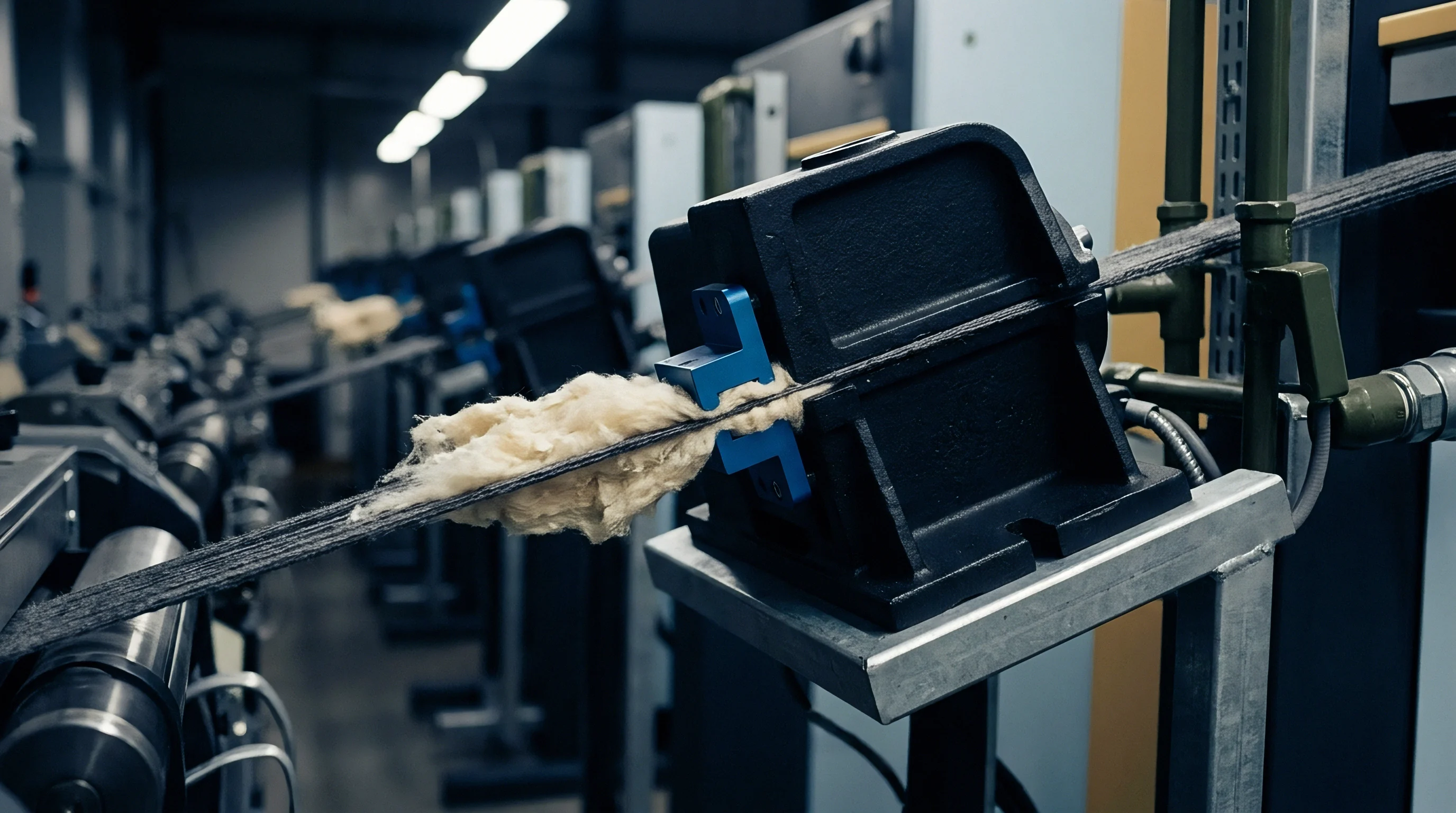
Gauge
Clearance distances between carding rollers dictate the mechanical shear applied to single fibers during web formation. When raw cotton or synthetic staple moves from the chute feed into the licker-in and cylinder zones, mechanical carding elements break open fiber tufts into individual state. Physical spacing between the main cylinder wire and the stationary or revolving flat tops defines the boundary between gentle fiber orientation and destructive mechanical impact.
Tight settings generate high velocity shear stress. When this shear stress exceeds the individual fiber tensile yield point, transverse cleavage occurs, converting full-length staple into short fiber fragments.
Clearance gaps govern mechanical stress. Setting the cylinder-to-flat spacing below 0.18 mm creates excessive mechanical pinching on medium-staple upland cotton. Tensile failure occurs primarily in the middle third of the fiber body where bending moments peak during carding action.
This structural breakdown shifts the fiber length distribution curve toward shorter length fractions. The Upper Half Mean Length drops while the Short Fiber Content increases in direct proportion to the reduction in setting clearance.
Clearance Discrepancies across Machine Zones
Setting tolerances vary significantly from the feed plate to the doffer section. The interface between the feed plate and the licker-in roller represents the first point of intense mechanical action. Setting this gap too close forces the licker-in teeth to comb through densely packed tufts before the fibers can accelerate, causing high rates of root-end breakage.
The table below outlines the relationship between specific cylinder-to-flat clearance settings and resulting fiber length parameters for a 1-1/8 inch (28.6 mm) upland cotton lot processed at a constant cylinder surface speed of 32 m/s.
| Clearance Setting (mm) | Upper Half Mean Length (mm) | Short Fiber Content by Weight (%) | Short Fiber Content by Number (%) | Nep Count (per gram) |
|---|---|---|---|---|
| 0.15 | 27.2 | 12.8 | 28.4 | 62 |
| 0.18 | 27.9 | 10.4 | 24.1 | 78 |
| 0.22 | 28.3 | 8.6 | 20.5 | 95 |
| 0.25 | 28.4 | 8.2 | 19.8 | 124 |
| 0.28 | 28.5 | 8.1 | 19.2 | 168 |
| Test results derived via AFIS ISO 23783-2 standard testing conditions at 65% RH and 20 degrees Celsius. | ||||
Tight settings increase fiber snapping. Operating at a tight 0.15 mm gauge reduces nep count significantly due to intense carding action, yet it damages the fiber matrix. The elevated short fiber content by weight compromises downstream spinning performance, leading to higher end-breakage rates on ring frames.
Cylinder-to-flat settings below 0.18 mm elevate short fiber content by 3.2 percentage points when processing upland cotton with a 28 mm staple length.
Mechanical stress during carding creates distinct failure patterns within incoming fiber lots depending on setting choices:
- Feed plate pinch degradation occurs when the distance between the feed nip and licker-in teeth is narrower than the mean crimp amplitude, pulling fibers apart before tuft loosening occurs.
- Transverse cylinder snapping results from cylinder-to-flat clearances smaller than the double-strand compressed diameter of incoming fiber neps, forcing direct fracture across the filament axis.
- Doffer transfer tearing happens when doffer-to-cylinder spacing exceeds efficient transfer limits, recirculating fibers back through the carding zone for repeated mechanical impact.
- Stationary flat abrasion develops when front pre-carding segments are set aggressively, stripping protective crimp and fracturing fiber tips prior to main carding action.
Selecting an excessively aggressive clearance setting to drive down nep figures damages raw fiber length, resulting in severe roving draft waves, elevated yarn count variability, and irrecoverable financial losses at the spinning frame.
Velocity
Rotational speeds of machine drives govern the rate of kinetic energy transfer to raw stock. Surface speeds of the licker-in, main cylinder, and doffer determine the linear impact force experienced by individual fibers upon contact with card clothing teeth. Modern high-performance carding machines operate with cylinder surface speeds exceeding 35 m/s to achieve throughput rates above 150 kg/h.
High rotational rates increase centrifugal forces, aiding trash extraction while elevating mechanical shock loading on single filaments.
Licker-in speed drives shear intensity. When licker-in rotational speed increases from 800 rpm to 1400 rpm, the tooth impact frequency against the incoming fiber beard rises proportionally. The kinetic energy transmitted per impact scales with the square of the tangential velocity.
High impact energy severs delicate cotton fibers at natural structural weak points along the primary cell wall. Viscose and polyester fibers suffer localized frictional heating under high velocity impact, leading to filament weakening and subsequent tensile breakdown.

Centrifugal Acceleration and Kinetic Fiber Cleavage
Impact forces at the taker-in roller strip trash particles while imparting extreme tensile impulses to pinned fibers. High cylinder peripheral speeds increase the relative speed differential between cylinder wire and flat wire points. This speed differential generates high aerodynamic drag within the carding micro-climate, altering fiber alignment relative to tooth faces.
Optimizing roller surface speeds requires a structured adjustment sequence to balance trash ejection against mechanical fiber damage:
- Establish baseline licker-in rotational speed according to raw fiber linear density, setting 800 rpm for fine long-staple cotton and up to 1200 rpm for coarse short-staple material.
- Adjust cylinder rotational speed in increments of 50 rpm while monitoring AFIS short fiber content by weight in the delivered sliver.
- Set flat linear speed to match trash loading, maintaining speed between 150 mm/min and 350 mm/min to prevent flat strip overloading without generating unnecessary fiber breakage.
- Calibrate doffer linear surface speed relative to cylinder speed to fix the total draft ratio and maintain stable fiber transfer efficiency across the doffer nip.
Linear speed determines contact duration. Excessively high main cylinder speeds reduce the dwell time of fibers in the carding zone, yet the violent acceleration during initial wire contact induces micro-fractures in the cellulose structure. These micro-fractures develop into complete fiber breaks during subsequent drafting on drawframes.
Elevating cylinder rotational speed improves nep extraction at the cost of accelerated short fiber generation on fine denier fibers.
Machinery manufacturers frequently argue that higher cylinder rotational speeds are mandatory to maintain web opening quality at elevated production rates, attributing resulting short fiber accumulation to poor bale management or low fiber maturity in raw material lots.
Pin
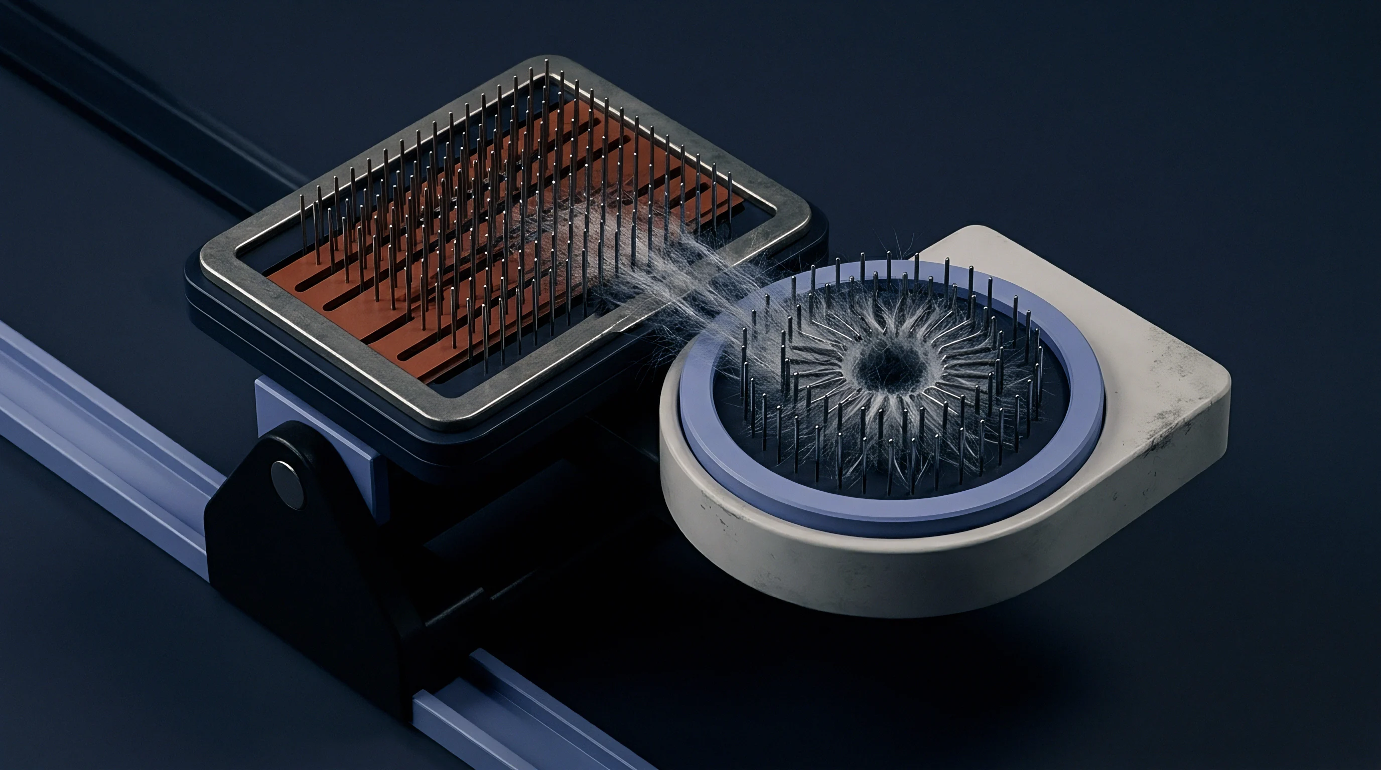
Wire teeth geometry on card clothing determines the point density and penetration angle into the fiber mass. Metallic card clothing consists of continuous steel wire strip stamped with precise tooth profiles, wound tightly around carding cylinders, doffers, and flats. Tooth height, front angle, land width, and point density (points per square inch or per square millimeter) dictate the force distribution during opening.
Finer wires with high point density split tufts effectively, but high tooth count reduces free volume between wires, risking fiber loading and jamming.
Pin angle dictates mechanical drag. Front angles ranging from 75 degrees to 85 degrees are standard for cylinder wires processing cotton. Acute front angles increase tooth penetration into fiber tufts, improving orientation and nep disentanglement.
Extremely aggressive angles trap single fibers at the tooth root, preventing smooth release to the doffer. Fibers trapped at the wire root undergo repeated mechanical stress from opposing flat teeth, causing multiple transverse fractures along the filament shaft.
What Wire Density Minimizes Short Fiber Generation?
Optimal wire selection balances point distribution against the linear density of individual filaments. Processing fine micro-denier synthetic fibers or high-maturity long-staple cotton requires lower point densities to allow sufficient spatial volume for fiber movement during carding. Duller wire bends fiber shafts.
Worn or burred card clothing teeth act like microscopic hooks, grabbing fibers and tearing them apart rather than allowing smooth slide-off during web transfer.
| Fiber Classification | Staple Length / Denier | Cylinder Wire Point Density (PPSI) | Tooth Front Angle (Degrees) | Threshold SFC Shift Delta (%) |
|---|---|---|---|---|
| Upland Cotton | 28.5 mm / 4.2 Mic | 860 – 920 | 78 – 80 | + 1.8 |
| Extra Long Staple Cotton | 35.0 mm / 3.6 Mic | 680 – 740 | 75 – 78 | + 1.2 |
| Viscose Rayon | 38.0 mm / 1.5 dtex | 540 – 620 | 82 – 85 | + 0.8 |
| Polyester Microfiber | 38.0 mm / 0.9 dtex | 480 – 560 | 85 – 88 | + 0.5 |
High point densities on long-staple natural fibers lead to excessive mechanical restraint. The resulting restriction prevents natural fiber straightening, multiplying stress points and driving up short fiber generation rates.
Maintaining card clothing integrity requires systematic monitoring of tooth geometry and surface condition:
- Tooth profile inspection involves microscopic assessment of wire tip sharpness and land width land to detect burrs or hook formation.
- Grinding frequency control establishes scheduled light grinding passes after processing defined metric ton thresholds to restore point geometry without lowering tooth height excessively.
- Side clearance verification checks spatial gap between adjacent wire rows to ensure trash particles do not jam teeth and cause local fiber loading.
- Base wire tension alignment measures mounting tension during clothing installation to prevent wire displacement or uneven height across the cylinder width.
Sharp, correctly angled wire teeth release fibers smoothly during doffer transfer, while worn wire with rounded points slips over fiber tufts, requiring tighter clearances that accelerate fiber cleavage.
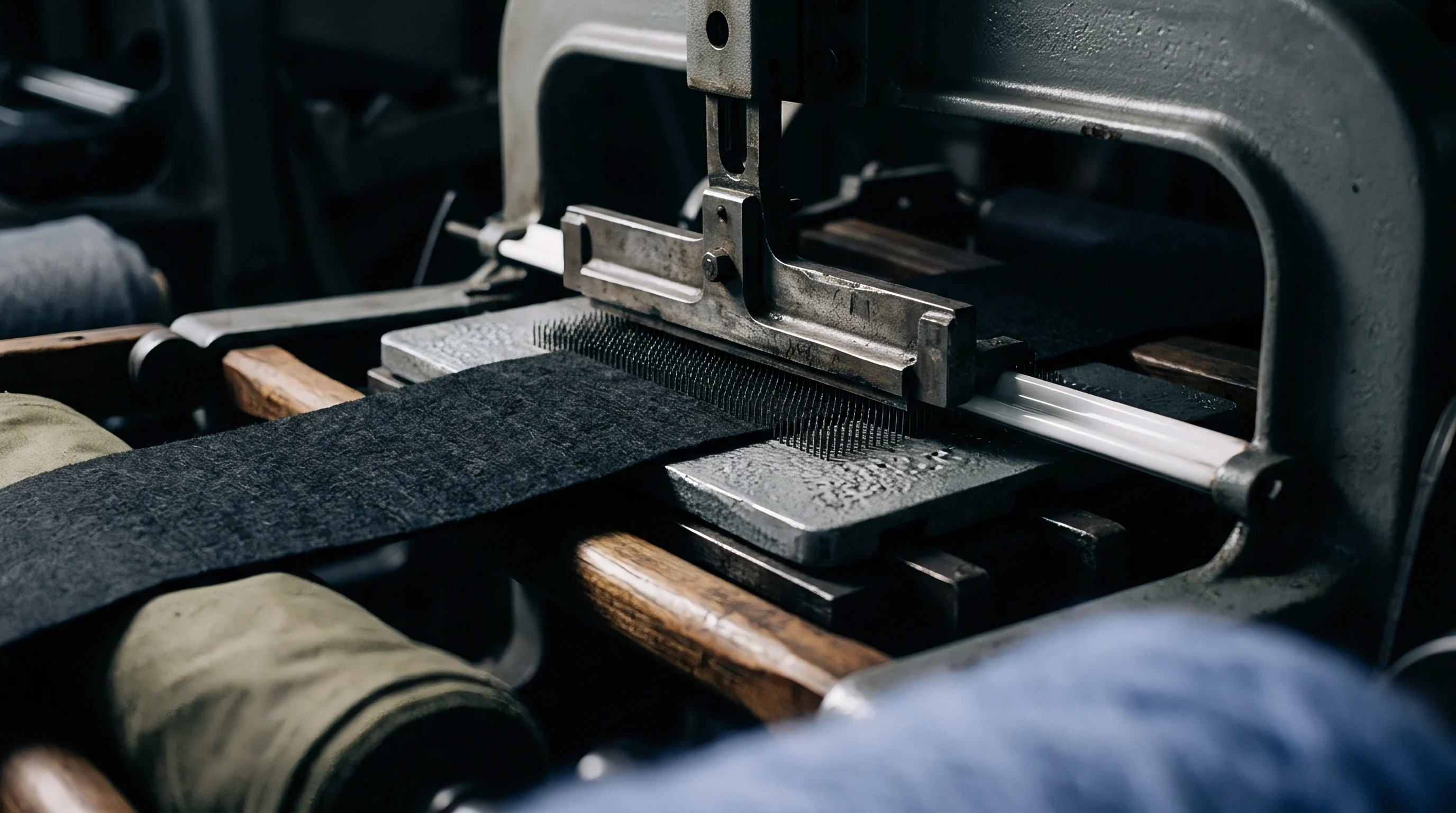
Sliver
Condensed fiber webs exiting the doffer enter the delivery trumpet under controlled linear tension. The structural quality of card sliver depends directly on the fiber length distribution retained after carding waste extraction. The main carding machine separates trash, heavy impurities, and un-carded fiber clumps into licker-in waste and flat strips.
Flat strip extraction selectively removes short fibers and neps while taking a fraction of spinnable long fibers out of the production stream.
Sliver weight shifts draft tension. High delivery speeds require precise sizing of trumpet apertures to maintain uniform sliver density without inducing mechanical crushing. Trumpet constrictions that are too small create localized friction, causing high strand tension that stretches and breaks fragile fibers within the sliver core.
Trumpet constrictions that are too large produce loose sliver susceptible to false drafting during can coiling and uncoiling.
Nep Extraction Ratios versus Short Fiber Accumulation
Separating trash and entangled neps relies on differential tooth angles between opposing carding surfaces. Nep Removal Efficiency (NRE) measures the percentage of incoming neps eliminated during carding, typically target ranges between 85% and 95%. Maximizing NRE through aggressive carding settings generates a side effect: higher short fiber ratios in the output sliver.
The increase in short fiber content weakens the cohesive force between fibers in the sliver strand, causing drafted sliver weight variations in subsequent drawframe passes.
ISO 23783-2 specifies a maximum allowance of 10.5 percent short fiber content by weight for carded sliver destined for fine ring spinning.
Card sliver quality certification requires technical documentation to confirm fiber integrity and process capability:
- AFIS fiber length array report displaying complete distribution curves for length by weight and length by number including short fiber percentages.
- Nep and trash content analysis sheet detailing residual seed coat neps, fiber neps, and dust particles per gram of carded sliver.
- Sliver mass evenness spectrograph registering capacitance CV% values and identifying periodic drafting wave spikes caused by mechanical roller eccentricity.
- Waste extraction logbook recording flat strip weight percentages, licker-in droppings, and total waste balance across production runs.
Short fiber fragments accumulated in card sliver float uncontrolled during roller drafting on drawframes, creating thick and thin places that directly lower finished yarn tenacity and elevated mass CV% values.
Arithmetic
Financial calculations linking fiber length degradation to raw material yield define the true landed cost of yarn production. When aggressive carding settings increase Short Fiber Content by Weight in delivered sliver, downstream process efficiency drops. In combed yarn manufacturing, excess short fibers generated during carding must be extracted at the comber as comber noil waste to maintain yarn strength standards.
Every additional percentage point of short fibers generated in carding directly translates into elevated comber waste percentage and lost raw material mass.
Carding action generates short fibers. To evaluate the financial impact of carding-induced fiber breakage, consider a worked calculation comparing two operational settings scenarios for a 10,000 kg lot of upland cotton purchased at $2.10 per kg ($21,000 total raw material outlay). The incoming cotton bale possesses an initial SFC(w) of 8.5% and an Upper Half Mean Length (UHML) of 28.5 mm.
In Scenario A (Optimized card settings: cylinder clearance 0.22 mm, licker-in speed 900 rpm), fiber breakage is minimized. SFC(w) in card sliver rises slightly to 9.8% (+1.3 percentage points shift). Flat strip waste extraction is set at 3.5%.
To achieve a target 7.0% SFC(w) in combed sliver for fine count spinning, the comber must extract 12.0% comber noil waste. Total process waste across carding and combing equals 15.5%. Effective combed yarn yield reaches 84.5% (8,450 kg output).
Net raw material cost per kg of spun output equals $21,000 divided by 8,450 kg, yielding $2.485 per kg.
In Scenario B (Aggressive card settings: cylinder clearance 0.16 mm, licker-in speed 1300 rpm), carding shear causes severe fiber snapping. SFC(w) in card sliver surges to 13.2% (+4.7 percentage points shift). Flat strip waste rises to 5.0% due to fiber fragmentation.
To remove the elevated short fiber volume and restore the 7.0% target SFC(w) in combed sliver, comber noil extraction must be increased to 17.5%. Total process waste increases to 22.5%. Effective yield drops to 77.5% (7,750 kg output).
Net raw material cost per kg of spun output increases to $21,000 divided by 7,750 kg, yielding $2.710 per kg.
Yield Losses and Comber Noil Escalation
Excess short fibers generated in carding directly drive up comber extraction requirements in high-count spinning mills. The table below demonstrates the progression of waste volume, raw material yield, and effective fiber cost across five card setting regimes with identical starting raw material.
| Setting Regime | Card Sliver SFC(w) (%) | Flat Strip Waste (%) | Required Comber Noil (%) | Total Waste (%) | Combed Yarn Yield (%) | Effective Raw Fiber Cost ($/kg) |
|---|---|---|---|---|---|---|
| Regime 1 (Gentle) | 9.2 | 3.0 | 10.5 | 13.5 | 86.5 | 2.428 |
| Regime 2 (Standard) | 9.8 | 3.5 | 12.0 | 15.5 | 84.5 | 2.485 |
| Regime 3 (Moderate) | 11.0 | 4.0 | 14.0 | 18.0 | 82.0 | 2.561 |
| Regime 4 (Aggressive) | 12.2 | 4.5 | 15.8 | 20.3 | 79.7 | 2.635 |
| Regime 5 (Severe) | 13.2 | 5.0 | 17.5 | 22.5 | 77.5 | 2.710 |
| Assumes baseline cotton purchase price of $2.10/kg and fixed target combed sliver SFC(w) of 7.0%. | ||||||
Combing waste removes short fragments. The cost differential between Regime 1 and Regime 5 equals $0.282 per kg of finished product. On a monthly production volume of 100 metric tonnes, setting-induced fiber breakage generates an unnecessary raw material penalty of $28,200.
Commercial supply agreements for combed yarn typically specify an explicit tolerance clause governing fiber length parameters: Standard sales contracts execute under ITMF guidelines stipulate that card sliver short fiber content variations exceeding 1.5 percentage points above declared specification entitle the buyer to a 2.0 percent price rebate per metric tonne delivered to offset comber noil adjustments.

Validation
Laboratory measurements of short fiber ratios require precise sampling protocols and calibrated instruments. Measuring short fiber shifts generated during carding demands high accuracy to isolate machine-induced damage from natural bale-to-bale variability. Testing laboratories rely on two primary instrumental systems: High Volume Instruments (HVI) and the Advanced Fiber Information System (AFIS).
Optical sensors count fiber ends. HVI systems report fiber length based on optical beard attenuation, providing Upper Half Mean Length (UHML), Uniformity Index (UNF%), and an estimated Short Fiber Index (SFI). SFI calculates short fiber content via empirical regression equations rather than direct single-fiber measurement.
SFI lacks sensitivity when detecting localized shifts in fiber breakage resulting from minor card setting adjustments.

Instrumental Differentiation between Measurement Systems
Comparing optical array data with individual fiber length distributions reveals structural discrepancies between testing platforms. AFIS instruments process individual fibers aerodynamically through individual optical sensors, counting and sizing thousands of single fibers per sample. AFIS generates direct distribution metrics: Short Fiber Content by Weight and Short Fiber Content by Number , defined as the percentage of fibers shorter than 12.7 mm (0.5 inch).
SFC by number exceeds SFC by weight. Because fine fiber fragments weigh significantly less than full-length fibers, numerical distributions report much higher short fiber values. A card sliver sample registering 9.5% SFC(w) typically exhibits an SFC(n) between 21.0% and 24.0%.
AFIS numerical short fiber content regularly exceeds weight-based short fiber ratios by seven to ten percentage points due to the high count of fine fiber fragments.
Acceptance testing procedures require drawing a minimum of ten independent sliver cans per carding line across three working shifts. Individual samples undergo conditioning at 20 degrees Celsius (+/- 2 degrees) and 65 percent relative humidity (+/- 4 percent) for 24 hours prior to testing under ISO 23783 protocols. Evaluating five replicates per can yields statistical confidence bands capable of identifying real short fiber shifts as small as 0.4 percentage points.
What remains unresolved across technical laboratories is whether aerodynamic single-fiber separation inside testing instruments creates additional micro-fractures in heavily stressed carded fibers, thereby overstating the actual short fiber shift produced by machine settings.