Rotor Groove Geometry Influence on Tensile Decay in Combed Yarns
Rotor groove angles above 50 degrees reduce combed yarn tensile decay under cyclic load by preventing fiber pinching and optimizing surface wrapper cohesion.
Profile
Geometric Parameters of Rotor Cross Sections
Open-end rotor spinning machines form yarn by collecting individual fibers inside the perimeter groove of a rapidly rotating rotor shell. The cross-sectional geometry of this collector channel defines the physical boundaries of the fiber wedge prior to twist insertion. Key structural variables include the groove angle, the base radius, channel depth, and surface coating texture.
Groove angles typically range from 40 degrees in narrow V-configurations to 60 degrees in wide U-configurations, while base radii vary between 0.20 millimeters and 0.60 millimeters. Narrow angles generate intense mechanical compression on the collected fiber ring, forcing individual filaments into close lateral proximity under centripetal acceleration.
Rotor speeds reaching 150,000 revolutions per minute subject fibers inside a 32-millimeter rotor to centripetal acceleration exceeding 40,000 times gravity. Under these forces, the geometric contact zone between the metallic rotor wall and the fiber mass governs the friction forces holding the ring together. Narrow V-grooves create a deep wedge that concentrates fiber mass at the apex.
Wide U-grooves permit the fiber band to spread laterally over a larger area, reducing peak packing density. Clean sliver reduces wear. Diamond-like carbon coatings and nickel-diamond matrix treatments maintain precise edge radii over extended operating cycles.
When surface treatments degrade, local micro-roughness alters the sliding friction of fibers during peel-off, initiating structural variations along the yarn axis.

Combed Sliver Behavior in Groove Wedges
Combing removes short fibers under 12.7 millimeters while eliminating neps and aligning long cotton staples parallel to the sliver axis. Introducing combed sliver into a rotor spinning system creates mechanical interactions distinct from carded preparation. Combed cotton features a high mean fiber length, often between 28.5 millimeters and 32.0 millimeters, with short fiber content held below 8 percent by weight.
Long staples require a larger curvature radius during twist transfer than carded fibers. Angle choice alters pressure. When combed sliver lands in a narrow 40-degree groove, long aligned fibers suffer severe mechanical pinching at the wedge base, forcing fiber ends to fold back onto themselves.
Folded fiber ends disrupt the continuous axial alignment achieved during combing. Instead of forming a uniform parallel ribbon, long cotton staples jam inside tight radius grooves, resisting smooth peel-off at the draw-off tube. The mechanical tension needed to pull jammed fibers out of the groove causes localized stretching and partial untwisting at the yarn formation point.
Core fibers carry load. In contrast, wide 55-degree grooves allow combed fibers to sit flat along the surface without excessive pinching, preserving the parallel orientation imparted by the comber. Fiber length changes twist.
The lack of short binding fibers in combed sliver means inter-fiber cohesion depends entirely on uniform pressure distribution across the groove profile.
| Groove Type | Groove Angle (Degrees) | Base Radius (mm) | Fiber Packing Density (g/cm³) | Peel-Off Resistance (cN) |
|---|---|---|---|---|
| Narrow V-Groove | 40 | 0.20 | 0.68 | 4.85 |
| Standard V-Groove | 46 | 0.30 | 0.59 | 3.90 |
| Modified U-Groove | 53 | 0.40 | 0.51 | 3.15 |
| Wide U-Groove | 60 | 0.55 | 0.43 | 2.60 |
Matching groove geometry to combed fiber length distribution dictates initial yarn structure. Misaligning these parameters destabilizes the twist propagation zone, leaving structural flaws that degrade yarn performance during subsequent high-tension unwinding. Does a narrower base radius increase core density sufficiently to offset the mechanical damage caused by fiber pinching at high rotor velocities?
Chamber
Centripetal Forces and Fiber Ring Compaction
Internal atmospheric pressure and mechanical forces inside the spinning housing dictate how individual fibers consolidate into a continuous ring. Fibers leave the opening roller pinned against the rotor wall by air currents generated by vacuum systems operating between 4.5 and 6.0 kilopascals. Once on the wall, fibers sliding down into the collector channel experience centripetal force proportional to rotor diameter and rotational speed squared.
High speeds generate heat. In carded spinning, random short fibers fill voids between longer staples, forming a self-locking matrix under centripetal pressure. Combed sliver lacks this fine filling material, leaving air voids between parallel long staples inside the groove.
Compaction in combed sliver relies on mechanical squeezing from the groove walls rather than random fiber interlocking. Narrow groove profiles press parallel staples into a dense core, but high surface friction against aluminum alloy rotor walls creates uneven sliding rates. Outer fibers in contact with the groove surface move slower than inner fibers residing in the core zone.
Low friction permits slip. This velocity differential creates internal shear stresses across the fiber ribbon before twist is introduced. When twist travels back from the navel, these internal shear stresses prevent real torque transfer into the center of the fiber bundle.
Wrapper Fiber Formation Mechanisms
Wrapper fibers form when incoming fibers bridge the gap between the rotor wall and the rotating yarn peel-off tail. These wrapper structures bind the parallel core fibers together, providing open-end yarn with its characteristic structural integrity. Combed cotton sliver generates longer, stiffer fibers that resist immediate bending around the yarn core.
When a long combed staple spans the groove, it creates an extended bridge rather than a tight helical wrap. Loose surface wraps fail to exert radial clamping force on the central fiber core, leaving core staples susceptible to axial slippage under load.
Tensile decay accelerates by 18 percent when combed staple length exceeds 31 millimeters in rotors with a groove angle under 45 degrees.
High rotor groove angles reduce the depth of the fiber wedge, allowing incoming fibers to hit the peel-off zone at wider angles. Wider landing angles promote tighter wrapper fiber formation around combed cores. Excessive wrapper tightness creates localized stress concentration points along the yarn tail.
Under downstream tensile loading, these stress points snap first, initiating a cascade of wrapper slippage that unravels core cohesion. Tenacity drops under strain. The ratio of core fibers to wrapper fibers in combed rotor yarns shifts dramatically with minor variations in groove base radius, fundamentally altering the yarn failure mechanism under stress.
- Apex Fiber Pinching occurs when long combed staples wedge into narrow radii below 0.25 millimeters, causing permanent fiber crimp deformation and localized strength loss.
- Bridge Extension Failure arises when long fibers span wide groove profiles without folding into the twist point, forming wild wrapper fibers that shed during winding.
- Uneven Core Compaction results from low centripetal compaction in wide U-grooves, producing low-density yarn cores with poor inter-fiber friction.
- Peel-Off Abrasion develops when sharp groove edges scrape the outer layer of combed fibers during high-speed yarn extraction through the navel.
Tight groove geometry paired with long staple cotton yields high initial static strength but accelerates structural breakdown during repeated cyclic extension. A wide groove radius with smooth wall transitions preserves fiber alignment at the expense of core packing density.

Fatigue
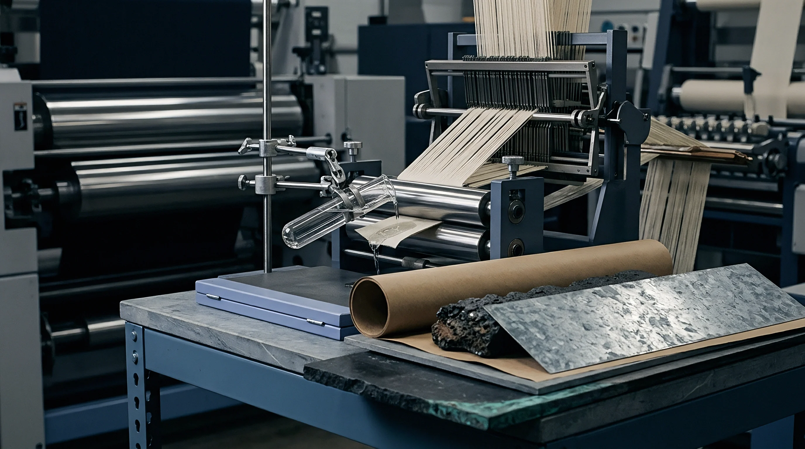
Can Narrow Rotor Grooves Reverse Tensile Decay in Combed Cotton?
Tensile decay defines the progressive loss of yarn tenacity under repeated low-magnitude tensile stress below the ultimate breaking load. In post-spinning operations such as high-speed warping, sizing, and knitting, yarns undergo thousands of tension cycles ranging between 15 percent and 35 percent of their static breaking force. Carded rotor yarns resist cyclic fatigue through a high population of short, entangled wrapper fibers that lock the core.
Combed rotor yarns rely on long-staple surface friction to maintain structural integrity under cyclic extension. Groove wear shifts geometry.
When combed rotor yarn experiences repeated tensile loading, core fibers lacking tight wrapper constraint begin to slip past one another. Narrow V-grooves increase initial yarn density, which helps resist low-cycle elongation. Under extended stress cycles exceeding 5,000 load applications, the sharp cross-sectional profile created by narrow grooves reveals its limitation.
Core fibers subjected to initial pinching during spinning exhibit localized microscopic shear fractures. These damaged points act as nucleation sites for inter-fiber slippage under cyclic tension, accelerating tenacity decay over time.
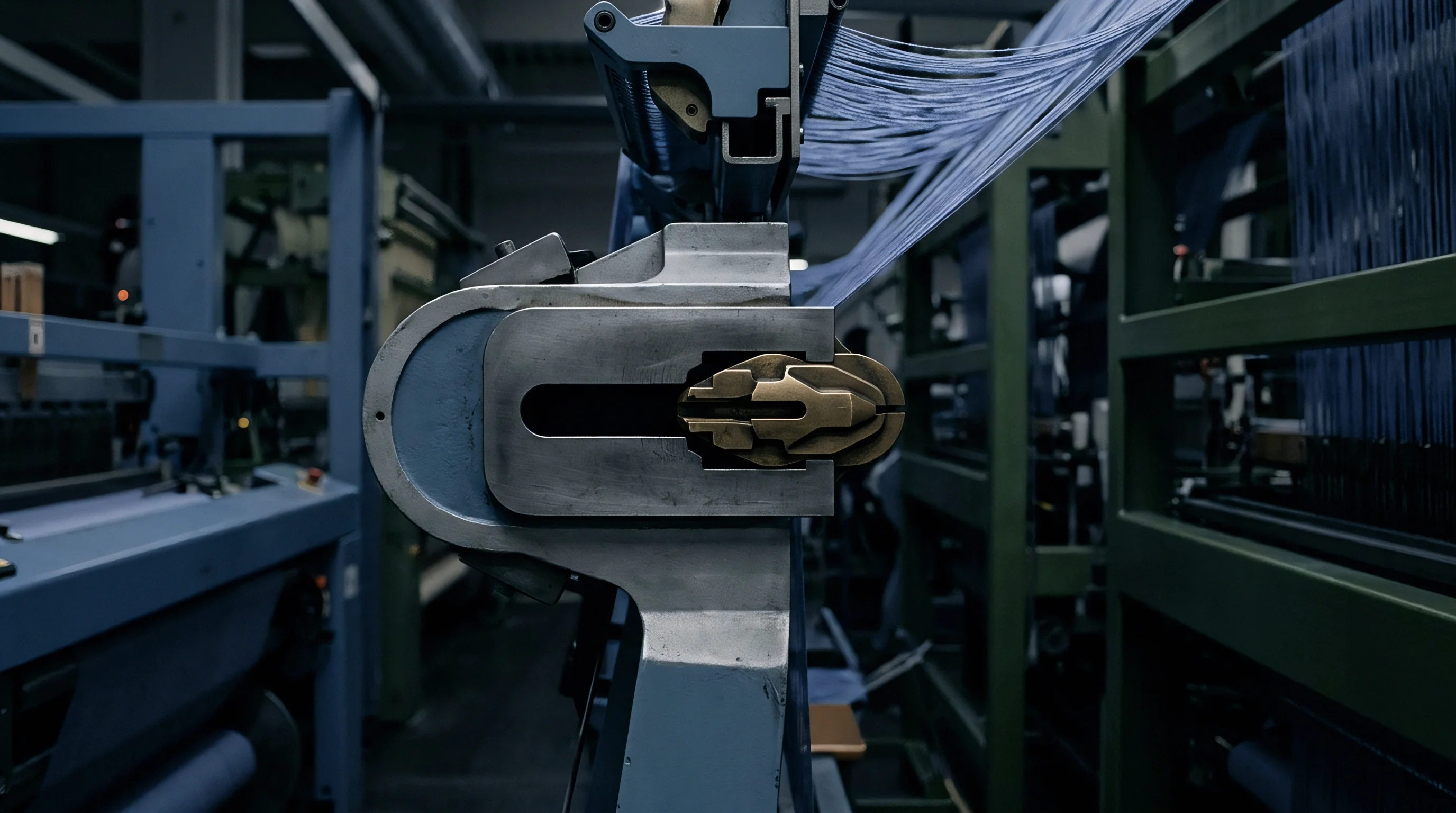
Inter-Fiber Friction and Wrapper Slippage Dynamics
Structural breakdown under cyclic load follows a two-phase deterioration pattern. In the initial phase, loose outer wrapper fibers shed from the yarn surface as it passes through ceramic guides and tension discs. Loss of surface wrappers reduces the radial clamping pressure holding the core together.
Testing catches early decay. In the second phase, core fibers unaligned by uneven groove friction slide axially, causing yarn diameter to narrow and local mass variation to increase. The loss of inter-fiber friction reduces breaking load by up to 30 percent prior to final tensile failure.
Standard testing under ISO 2062 reveals tenacity loss exceeding 2.5 centinewtons per tex when yarn passes over high-friction navels under cyclic tension.
Rotors featuring a 53-degree groove angle and a 0.40-millimeter base radius produce combed yarns with uniform wrapper density across the yarn axis. Uniform density prevents failure. This structural balance minimizes local stress concentrations, allowing the yarn to distribute cyclic loads across thousands of parallel long staples.
Combing strips short staple. The rate of tensile decay slows significantly in yarns produced with optimized U-groove geometry, preserving breaking strength through subsequent weaving operations.
| Yarn Count (Ne) | Groove Angle / Radius | Initial Tenacity (cN/tex) | Tenacity After 5,000 Cycles (cN/tex) | Tensile Decay Rate (%) |
|---|---|---|---|---|
| Ne 20/1 Combed | 40° / 0.20 mm | 15.8 | 12.1 | 23.4 |
| Ne 20/1 Combed | 53° / 0.40 mm | 14.9 | 13.2 | 11.4 |
| Ne 30/1 Combed | 40° / 0.20 mm | 14.2 | 10.3 | 27.5 |
| Ne 30/1 Combed | 53° / 0.40 mm | 13.6 | 11.8 | 13.2 |
| Ne 40/1 Combed | 40° / 0.20 mm | 12.8 | 8.7 | 32.0 |
| Ne 40/1 Combed | 53° / 0.40 mm | 12.2 | 10.1 | 17.2 |
High tension causes breaks. Choosing an excessively sharp rotor groove angle to raise static single-strand tenacity values generates brittle yarn structures that degrade rapidly under operational tension on downstream production machinery.
Bench

Standardized Testing of Cyclic Strength Degradation
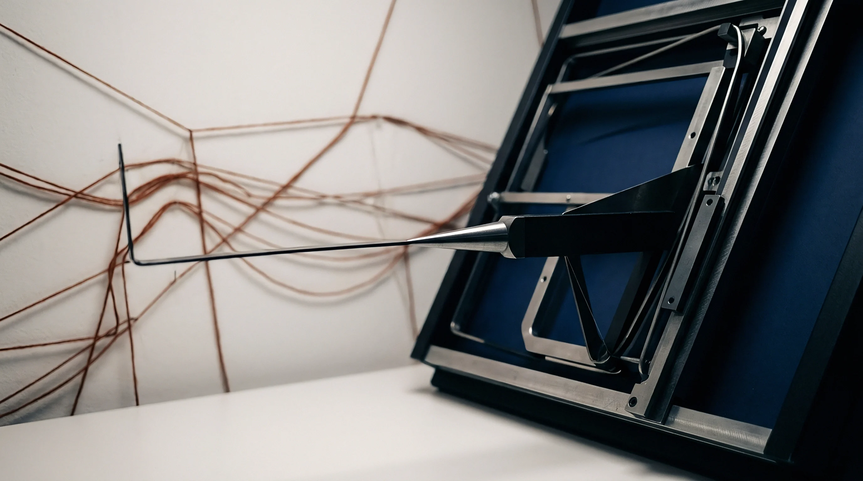
Laboratory quantification of tensile decay demands rigorous conditioning and precise test equipment setups. Test specimens must condition in standard atmosphere at 20°C ± 2°C temperature and 65% ± 2% relative humidity for 24 hours prior to evaluation under ISO 139 protocols. Tensile testing utilizes single-strand automated testers operating under constant rate of extension parameters.
Tensile decay protocols apply continuous cyclic loads between specified load limits before pulling the specimen to final break.
Evaluation requires testing minimum sample sets drawn across multiple spinning positions to isolate rotor groove wear from general machine drafting variance. Standard single-strand breaks capture initial ultimate strength but fail to measure decay velocity under fatigue loading. Cyclic fatigue testing applies repetitive strain cycles equivalent to 20 percent of nominal breaking force at a frequency of 5 hertz.
Measuring tenacity loss at 1,000, 3,000, and 5,000 cycle intervals charts the precise structural decay curve of combed rotor lots.
Laboratory Protocols for Tenacity Loss Quantification
Accurate bench evaluation requires strict adherence to standardized mechanical verification sequences to isolate geometric rotor wear from raw cotton quality drift.
Wider groove radii preserve core alignment in long-staple combed lots but demand elevated rotor speeds to prevent fiber accumulation slip.
- Draw 20 yarn packages randomly across the spinning frame, selecting ten packages from outer rotor positions and ten from center positions.
- Condition all selected packages at 20°C and 65% relative humidity for 24 hours in a certified laboratory environment.
- Perform 50 baseline single-strand breaking force tests per package according to ISO 2062 at a gauge length of 500 millimeters and speed of 500 millimeters per minute.
- Mount secondary samples on a cyclic tensile fatigue tester and apply 5,000 load cycles between 5 percent and 25 percent of baseline breaking load.
- Transfer cyclically loaded specimens immediately back to the ISO 2062 single-strand tester to measure retained breaking tenacity in centinewtons per tex.
- Calculate total tensile decay percentage by comparing baseline single-strand tenacity to post-fatigue retained tenacity across all package positions.
Mills often explain unexpected yarn strength decay during downstream winding by citing raw cotton micronaire fluctuations or ambient humidity shifts in the blowroom. Sourcing engineers eliminate these excuses by checking rotor run hours and groove wall micro-roughness profiles under optical microscopy before accepting raw lot delivery.
Yield

Worked Economic Calculation for Combed Rotor Spinning
Evaluating raw material allocation alongside machine tooling performance requires balancing higher combed sliver procurement costs against rotor replacement intervals and yarn quality tiers. Combed sliver costs approximately 0.35 USD to 0.50 USD more per kilogram than carded sliver due to noil removal losses ranging from 12 percent to 16 percent. Spun on poorly specified rotor profiles, expensive combed fibers suffer strength loss that eliminates their performance edge, destroying production margins.
Consider a production run of 50,000 kilograms of Ne 30/1 combed cotton yarn manufactured on 1,200 rotor positions operating at 130,000 revolutions per minute. Assume Option A utilizes a 40-degree narrow V-groove with a 0.20-millimeter base radius designed for maximum static tenacity. Option B utilizes a 53-degree modified U-groove with a 0.40-millimeter base radius designed for fatigue resistance.
Option A delivers high initial tenacity of 14.2 cN/tex, but experiences high downstream warp breakage rates of 1.8 stops per 100,000 meters due to a 27.5 percent tensile decay rate under cyclic stress. Option B delivers lower initial static tenacity of 13.6 cN/tex, but maintains structural integrity with a 13.2 percent decay rate, yielding downstream warp breakage rates of 0.4 stops per 100,000 meters.
Fiber migration across sharp rotor grooves generates local mass variation that manifests as yarn unevenness under high twisting tension.
Downstream weaving efficiency increases from 88.5 percent under Option A to 94.2 percent under Option B. Stopped loom downtime costs approximately 0.12 USD per loom-hour in lost production capacity. Over a 50,000-kilogram order, the higher weaving efficiency of Option B saves 14,200 USD in weaving operational costs while reducing total rotor replacement frequency by 30 percent due to lower wall abrasion in wider groove angles.
| Operational Metric | Option A (40° / 0.20 mm Groove) | Option B (53° / 0.40 mm Groove) | Variance / Performance Impact |
|---|---|---|---|
| Sliver Type & Noil Extraction | Combed (14% Noil) | Combed (14% Noil) | Baseline Material Parity |
| Initial Static Tenacity (cN/tex) | 14.2 | 13.6 | -4.2% (Initial Static Loss) |
| Tensile Decay After Fatigue (%) | 27.5 | 13.2 | -14.3% (Fatigue Reduction) |
| Warp Stop Rate (Stops/100,000m) | 1.8 | 0.4 | -77.7% (Downstream Efficiency Gain) |
| Weaving Shed Efficiency (%) | 88.5 | 94.2 | +5.7% Output Volume |
| Rotor Cleaning Interval (Hours) | 24 | 72 | +200% Tooling Lifecycle Extension |
| Landed Yarn Cost per Kg (USD) | 3.85 | 3.68 | -0.17 USD/kg Net Finished Savings |
Supply contracts specifying minimum breaking tenacity must include maximum allowable tensile decay percentages measured after 5,000 load cycles under ISO 2062 protocols to prevent mills from shipping brittle yarns optimized solely for static breaking tests.

Audit
Procurement Specifications for Combed Rotor Yarns
Establishing commercial procurement specifications for combed rotor yarns demands strict boundaries on both static mechanical parameters and dynamic fatigue limits. Standard contracts quoting basic single-strand breaking tenacity leave buyers vulnerable to shipments that pass initial lab clearance but disintegrate on high-speed weaving looms. Procurement documentation requires full disclosure of rotor geometry, including groove angle, base radius, rotor diameter, and surface coating type used during manufacturing.
Verification protocols must tie raw lot acceptance directly to post-fatigue retained strength metrics. A robust purchasing specification limits maximum tensile decay to 15 percent of baseline single-strand breaking force following 5,000 fatigue cycles. Mill qualification audits require verifying opening roller clothing wire density, rotor groove cleaning schedules, and navel replacement cycles.
Rotor groove wear exceeding 0.05 millimeters from factory nominal geometry automatically invalidates lot quality certifications.

Tariff Classification and Fiber Content Tolerances
Cross-border shipments of combed cotton rotor yarns fall under Harmonized System tariff heading 5205, covering single cotton yarn containing 85 percent or more by weight of cotton. Subheading classifications distinguish between uncombed and combed fibers, with combed yarns commanding distinct duty schedules in key importing jurisdictions. Custom clearance documentation must present quantitative fiber analysis under ISO 1833 alongside combing verification certificates showing short fiber content below 8 percent by weight.
Misclassifying carded rotor yarn as combed rotor yarn to secure tariff concessions exposes importers to severe duty penalties and shipment seizures. Customs laboratories utilize scanning electron microscopy and fiber length distribution profiling to verify combing claims. Duty rates depend on count.
Blends combining combed cotton with synthetic fibers like polyester require precise weight ratio documentation, as tariff headings shift to Chapter 55 when synthetic staple content reaches 50 percent or higher by weight.
- Groove Geometry Certification mandates mill documentation specifying rotor angle, radius, and coating type for every production lot.
- Fatigue Retained Tenacity establishes a minimum threshold of 85 percent retained single-strand breaking force following cyclic fatigue testing.
- Combing verification Dossier demands mean fiber length analysis and short fiber content metrics proving complete combing extraction.
- Harmonized Tariff Compliance aligns physical fiber classification with HS 5205 rules to avoid misdeclaration penalties at customs ports.
Structuring commercial purchase orders around physical groove parameters, post-fatigue tenacity limits, and verified tariff declarations protects landed margins while guaranteeing yarn performance across high-speed fabric manufacturing table operations.