Calculating Package Diameter Friction Curves across High Speed Warping Creels
Calculating package friction curves links balloon collapse and capstan drag to calibrate creel tensioners, preventing streaks and warp stops across the beam.

Spool
Conical packages feeding modern direct warping machines operate under severe rotational demands at delivery speeds between eight hundred and twelve hundred metres per minute. Yarn departs the package over-end while the wound structure sits stationary on the creel peg. This geometry forces the unwinding point to rotate around the package perimeter at thousands of revolutions per minute, producing a revolving yarn balloon dictated by package diameter, yarn count, and axial withdrawal speed.
Tension climbs as diameter decreases. When a package is full, the diameter reaches two hundred eighty to three hundred millimetres. At that dimension, a linear yarn velocity of one thousand metres per minute produces an angular unwinding velocity of approximately one hundred eleven radians per second.
As the yarn winds off down to the empty cardboard core, the unwinding radius contracts to thirty millimetres or less. That radial contraction forces the rotational speed to escalate above five hundred fifty radians per second. The rotating yarn end experiences substantial centrifugal forces that project it outward against atmospheric drag, forming a standing balloon whose envelope changes continuously across the depletion cycle.

Rotational Velocity and Balloon Geometry
A delivery velocity of one thousand metres per minute forces the unwinding point around the package perimeter at variable angular rates. The yarn departs alternately from the package nose and the package shoulder across each traverse stroke. When unwinding from the package base, the yarn sweeps across the wound surface of the cone, generating surface rubbing friction that adds directly to the balloon tension.
At the nose, the balloon length extends, shifting the apex angle and altering the air resistance encountered by the yarn envelope.
Empty packages spin faster. The mechanical consequence appears in the physical envelope of the unwinding balloon. Large packages produce a single wide balloon with high air resistance and low takeoff drag from the cone surface.
Small packages near the empty core generate shorter, tighter multi-wave balloons that collapse repeatedly against the tube. Centrifugal force drives balloon expansion. This centrifugal acceleration scales with the square of the angular velocity and linearly with the radius, creating non-linear physical loads on the filament as the cone empties.
| Package State | Diameter (mm) | Angular Velocity (rad/s) | Rotational Speed (rpm) | Centrifugal Acceleration (m/s²) |
|---|---|---|---|---|
| Full Cone | 280 | 119.0 | 1136 | 1983 |
| Three Quarter | 220 | 151.5 | 1446 | 2525 |
| Half Package | 160 | 208.3 | 1989 | 3472 |
| Quarter Package | 100 | 333.3 | 3183 | 5555 |
| Bare Tube Core | 58 | 574.7 | 5488 | 9578 |
Creel suppliers routinely maintain that automated balloon limiter rings neutralize any package shape discrepancies before yarn enters the tensioning units.
Capstan
Guide surfaces along the yarn delivery path impose frictional resistance through sliding contact. Yarn departs the package balloon and threads through ceramic pigtails, balloon control rings, tensioner guide eyelets, and gathering combs before reaching the warper headstock. Every ceramic contact point acts as a capstan, redirecting the yarn path and amplifying upstream tension according to the Euler-Eytelwein formulation.
Contact angle governs friction. A yarn entering a ceramic eyelet under tension departs that eyelet under a multiplied tension governed by the dynamic friction coefficient and the angle of wrap in radians. While a single ceramic eyelet may present an angle of wrap of merely twenty to thirty degrees, a high-speed warping creel forces the yarn through eight to fourteen sequential ceramic contact points along the creel bay.
Upstream fluctuations created by package diameter changes enter this multiplier chain at the very beginning.
Yarn tension escalates through successive ceramic eyes because each contact wrap multiplies incoming drag rather than adding a fixed resistance.
Dynamic Friction along Ceramic Eyelets
Aluminum oxide eyelets polished to surface roughness values below zero point four micrometres interact directly with synthetic spin finishes. The dynamic coefficient of friction does not remain constant during production. Spin finish oils applied to polyester or polyamide filaments shear under high linear speeds, generating hydrodynamic lubrication effects that depend heavily on guide temperature and line velocity.
Ceramic surfaces accumulate polymer debris. Sintered titanium dioxide or high-purity alumina guides dissipate frictional heat differently, and guide temperatures regularly climb above sixty degrees Celsius during continuous warping runs at one thousand metres per minute.
Static friction exceeds dynamic drag. When the warper stops to mend a broken end, the yarn settles against the ceramic guide surfaces. Upon restarting, static breakaway friction spikes the initial takeoff tension until the dynamic hydrodynamic film re-establishes itself.
The composition of the spin finish, specifically the neat oil percentage and water emulsifier balance, dictates the stability of this friction coefficient across varying running speeds.
Why Does Tension Escalate as Package Diameter Depletes?
Angular acceleration increases fourfold as the yarn unwinds from the outermost wraps down to the bare cardboard tube. At the bare tube, the angle between the unwinding yarn end and the package surface becomes acutely steep. The yarn drags across preceding wraps of yarn along the cone body before detaching into the balloon space, adding yarn-on-yarn sliding resistance to the equation.
Balloon height collapses near the nose. As the balloon radius contracts, the yarn fails to clear the package nose rim cleanly, generating intermittent slapping impacts against the cone edge that appear on tension tensiometers as high-frequency tension spikes.
- Outer Package Depletion Stage presents low angular velocity, wide balloon radius, minimal package surface drag, and baseline takeoff tension ranging from four to six centinewtons.
- Mid Body Transition Stage introduces contracting balloon boundaries, doubling angular velocity, and establishing continuous sliding contact across the wound cone taper.
- Core Approach Phase initiates multi-node balloon collapse, where centrifugal force fails to maintain a clean envelope, causing yarn to impact the cardboard tube collar.
- Terminal Bobbin Runout produces severe angular pull, maximum yarn-on-yarn rubbing friction, and sudden takeoff tension peaks exceeding twenty-five centinewtons at the creel peg.
Higher package taper angles smooth out unwinding resistance, whereas flatter cones magnify yarn snags during core depletion.

Arithmetic
Theoretical derivation of unwinding resistance begins by isolating the centripetal, Coriolis, and boundary friction forces acting on the yarn segment. Total yarn tension at the warper headstock represents the mathematical sum of takeoff drag, ballooning air resistance, and cumulative capstan multiplication across all creel guide elements. Calculating this curve across package diameters enables creel engineers to calibrate compensatory tensioning systems accurately.
Linear speed remains fixed. Let delivery velocity be represented by the variable v in metres per second, package instantaneous radius by R in metres, and yarn linear density by rho in kilograms per metre. The takeoff tension T sub zero emerging from the unwinding point at the package surface combines yarn withdrawal tension and centrifugal balloon dynamics according to fundamental mechanical laws:
T sub balloon equals rho multiplied by the square of v, modified by the package radius to balloon limiter radius ratio. As the radius R decreases, the angular velocity omega equals v divided by R. The centrifugal acceleration term scales inversely with the square of the package radius. Concurrently, yarn sliding drag across the package cone follows the exponential capstan equation where yarn wrap angle across the package shoulder increases as the package diameter diminishes.
A bare tube diameter of fifty-eight millimetres generates thirty-four centinewtons of takeoff drag at one thousand metres per minute when unwinding textured polyester.
What Mathematical Model Predicts Takeoff Tension Curves?
Analytical formulations treat the yarn length departing the package shoulder as an elastic continuum subjected to rotating boundary constraints. The takeoff tension T sub zero at the package nose is modeled through the following composite equation:
T sub zero equals T sub unwind plus one half rho multiplied by the square of omega multiplied by the square of R, multiplied by the air drag coefficient factor, plus the package surface rubbing component F sub rub.
The package rubbing component F sub rub scales inversely with the sine of the cone semi-angle theta sub c and inversely with package diameter. Downstream tension through n successive ceramic guides follows the cumulative capstan relation:
T sub final equals T sub zero multiplied by the exponential product of the dynamic friction coefficient mu sub i and the wrap angle alpha sub i for each guide, plus the tension added by the mechanical tensioner unit T sub add.
Mechanical failure modes occur when this mathematical relationship is neglected during machine setup:
- Filament Shear Fracture arises when cumulative capstan tension exceeds eighteen percent of single-end tensile strength, snapping individual microfilaments against ceramic guides.
- Balloon Collapse Snarls emerge when depleted core diameters produce tension drops below the threshold required to clear the cone nose, wrapping yarn around the peg spindle.
- Tensioner Chattering Oscillation develops when high-frequency cyclic takeoff pulses excite harmonic resonance in mechanical spring-loaded disc washers, destroying tension uniformity.
- Thermal Lubricant Glazing takes place when cumulative contact friction elevates ceramic guide temperature beyond eighty degrees Celsius, melting spin finish waxes into abrasive residues.
Worked Formulation for Textured Polyester
A technical polyester yarn lot of one hundred sixty-seven decitex serves to demonstrate the numerical progression across unwinding stages. Linear density rho equals zero point zero one six seven grams per metre, which translates to one point six seven multiplied by ten to the power of negative five kilograms per metre. Warper running speed is set at one thousand metres per minute, equivalent to sixteen point six seven metres per second.
The yarn path traverses three ceramic eyelets with individual wrap angles of thirty-five degrees, forty degrees, and forty-five degrees respectively, yielding a total wrap angle of one hundred twenty degrees, or two point zero nine four radians. Dynamic ceramic friction coefficient mu is established at zero point one eight under conditioned factory atmosphere. A disc tensioner adds a baseline mechanical clamping drag of eight centinewtons.
At full package diameter of two hundred eighty millimetres, the package radius R equals zero point one four metres. The angular velocity omega equals one hundred nineteen radians per second. Calculated baseline takeoff tension T sub zero measures five point two centinewtons.
Applying the cumulative capstan multiplication across the three eyelets yields a multiplier equal to the exponential of zero point one eight multiplied by two point zero nine four, which equals one point four five八. Multiplying five point two by one point four five八 produces seven point five八 centinewtons. Adding the mechanical tensioner force of eight centinewtons produces a final delivery tension of fifteen point五八 centinewtons at the front comb.
At bare core diameter of fifty-eight millimetres, package radius contracts to zero point zero two nine metres. Angular velocity climbs to five hundred seventy-five radians per second. High rotational acceleration and steep shoulder rub elevate takeoff tension T sub zero to twenty-three point four centinewtons.
Passing through the identical ceramic eyelet arrangement multiplies this value by one point four五八, resulting in thirty-four point one centinewtons. Adding the identical eight centinewton tensioner load generates a final delivery tension of forty-two point one centinewtons. Tension more than doubles across the package lifespan.
| Diameter (mm) | Takeoff Tension T0 (cN) | Post Guide 1 (cN) | Post Guide 2 (cN) | Post Guide 3 (cN) | Final at Warper Head (cN) |
|---|---|---|---|---|---|
| 280 | 5.20 | 5.80 | 6.58 | 7.58 | 15.58 |
| 220 | 6.85 | 7.64 | 8.67 | 9.99 | 17.99 |
| 160 | 9.40 | 10.48 | 11.90 | 13.71 | 21.71 |
| 100 | 14.60 | 16.28 | 18.49 | 21.29 | 29.29 |
| 58 | 23.40 | 26.10 | 29.64 | 34.12 | 42.12 |
| Method conditions: 1000 m/min delivery velocity, 167 dtex polyester, mu = 0.18, total wrap angle = 120 degrees, mechanical tensioner addition = 8.0 cN. | |||||
Whether real-time laser diameter sensors can adjust individual electronic disc tensioners fast enough to counteract micro-balloon collapses during rapid deceleration remains unproven on commercial warping floors.

Bank
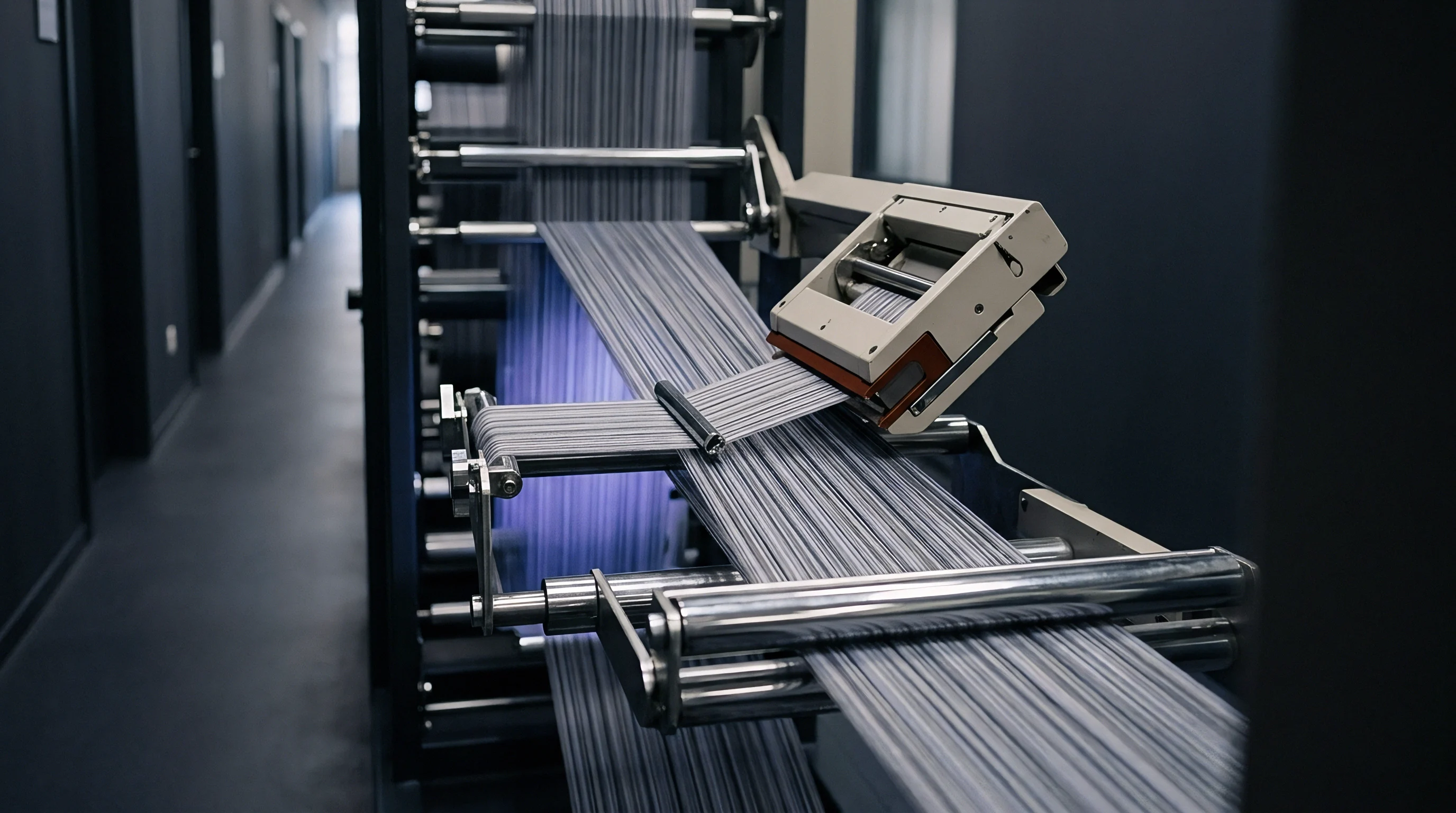
Creel frames arrange hundreds of yarn packages in multi-tiered rows extending up to thirty metres from the headstock gathering reed. A standard V-creel or parallel creel carries six to twelve vertical tiers and up to eighty package bays per side. The spatial location of each package creates massive differences in the downstream path length and total cumulative guide wrap angles experienced by individual ends.
Trailing ends whip violently. An end originating at the front tier closest to the warper headstock travels through fewer than three metres of free air and two directional guide eyelets before reaching the comb. An end originating from the rearmost top tier travels through twenty-eight metres of creel corridor, supported by twelve or more intermediate ceramic rings.
The friction accumulated along that rearmost trajectory compounds the diameter-induced tension curve.
A warp sheet tension variance exceeding eight percent across the creel array invalidates the mill warranty under standard supply contracts by creating irreversible dye stripiness.
Spatial Gradients across Creel Arrays
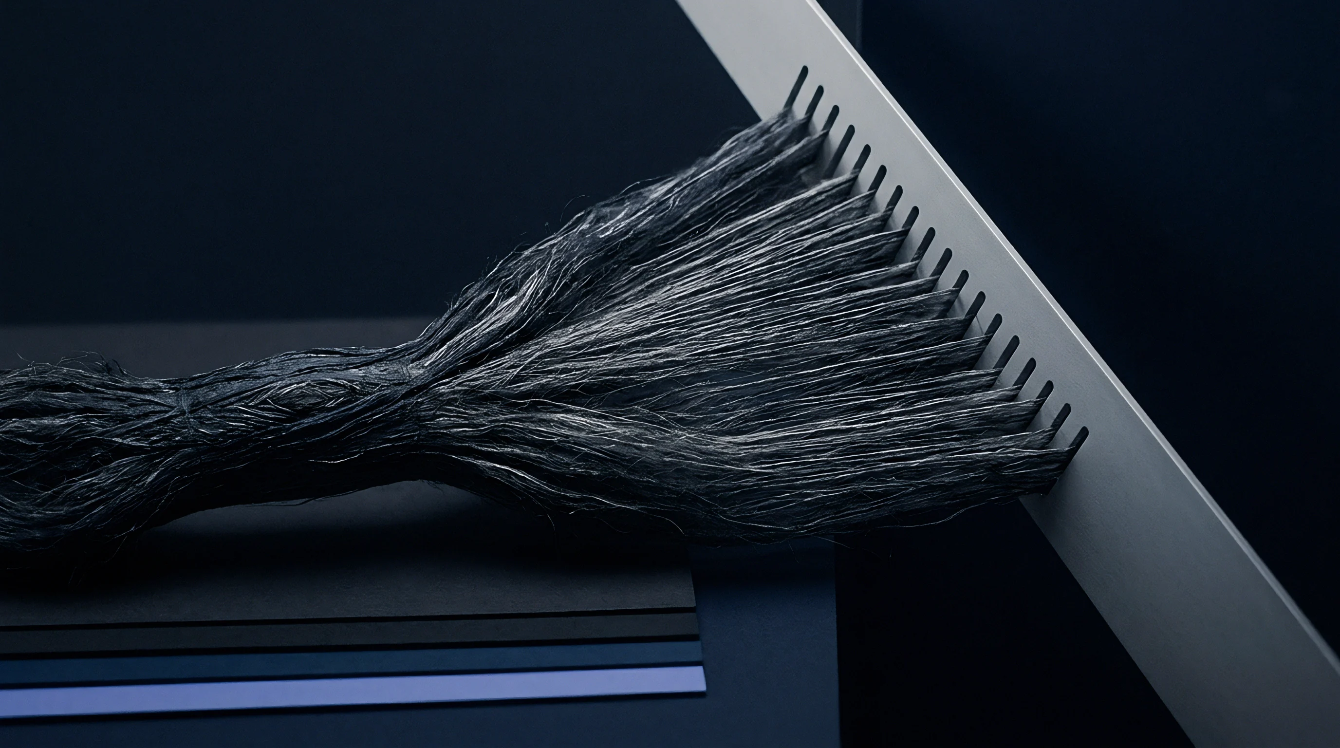
Yarns originating from the furthest creel bays pass through twelve or more guide rings before reaching the front combs. This physical layout establishes a permanent tension gradient across the warp sheet unless deliberate compensatory adjustments are implemented. Rear packages suffer from both higher static guide friction and greater air resistance along their extended transport spans.
When rear packages reach bare core depletion simultaneously with front packages, tension at the headstock from the rear ends spikes to unsustainable levels.
The unwinding point moves rapidly. Because high-speed warping creels process five hundred to one thousand ends simultaneously, maintaining uniform sheet tension across the beam width requires precise zone balancing. The factory floor cannot treat every spindle identically.
Tension Balancing Strategies for Beaming
Individual electromagnetic brakes compensate for both position distance and package depletion cycles. Modern creels divide packages into distinct geographic zones, applying graduated braking pressures that offset path length disparities. Packages situated at the creel rear receive lighter baseline clamping, while packages near the gathering reed receive heavier mechanical restraint.
Calibrating these systems requires a structured operational decision protocol:
- Zonal Creel Calibration establishes stepped baseline damping forces across creel bays to equalize front-to-back delivery drag before high-speed running begins.
- Diameter Stepped Braking reduces tensioner clamping force progressively as operational run timers record cumulative yarn length withdrawn from the creel.
- Yarn Path Alignment Inspection verifies that ceramic guide eyes sit precisely collinear with cone package centerlines to prevent asymmetric balloon drag.
- Tensioner Surface De-glazing mandates ultrasonic cleaning of ceramic and steel disc surfaces every five hundred operating hours to preserve calibrated friction coefficients.
Standard international supply contracts incorporating BISFA delivery rules permit a maximum three percent tension variation coefficient, shifting dispute liability onto the warper operator whenever creel zoning calibration records are missing.

Beam
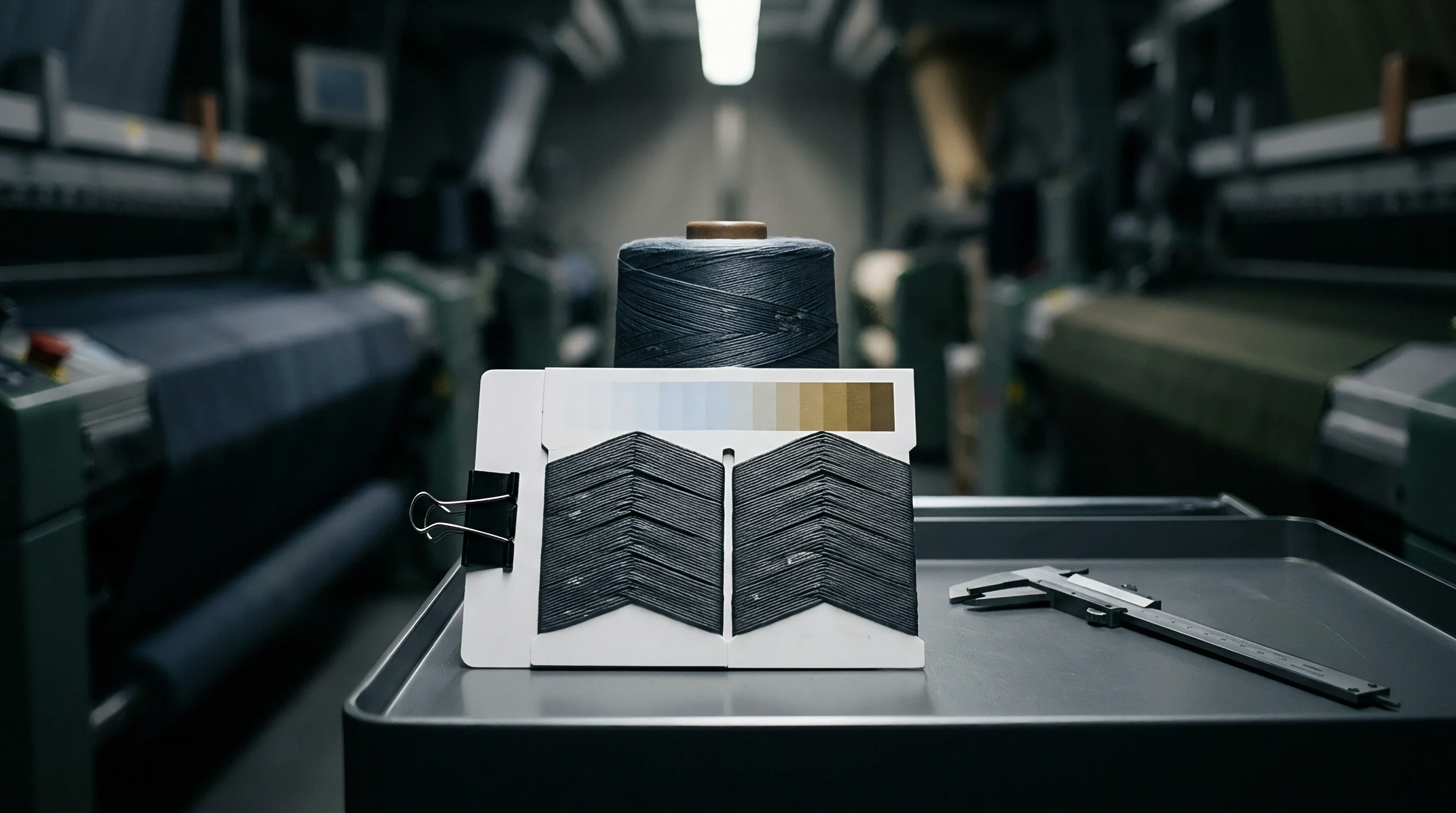
The cylindrical warp collector compacts thousands of individual yarn ends under high rotational winding torque. The structural integrity of the resulting beam depends entirely on uniform winding density from the barrel core to the outer circumference. When tension fluctuates across the creel during package depletion, these disparities translate directly into variable package hardness and uneven yarn elongation across the beam length.
Tight ends produce optical barre. When ends from depleted packages wind onto the beam under forty centinewtons while adjacent ends from fuller packages wind at eighteen centinewtons, the tighter ends undergo permanent plastic deformation. Filament elongation causes uneven dye uptake.
Synthetic polymer chains orient themselves more tightly along the fiber axis under high drawing tension, reducing amorphous regions where dyestuff molecules diffuse during wet processing.
Filament Elongation and Dye Receptivity
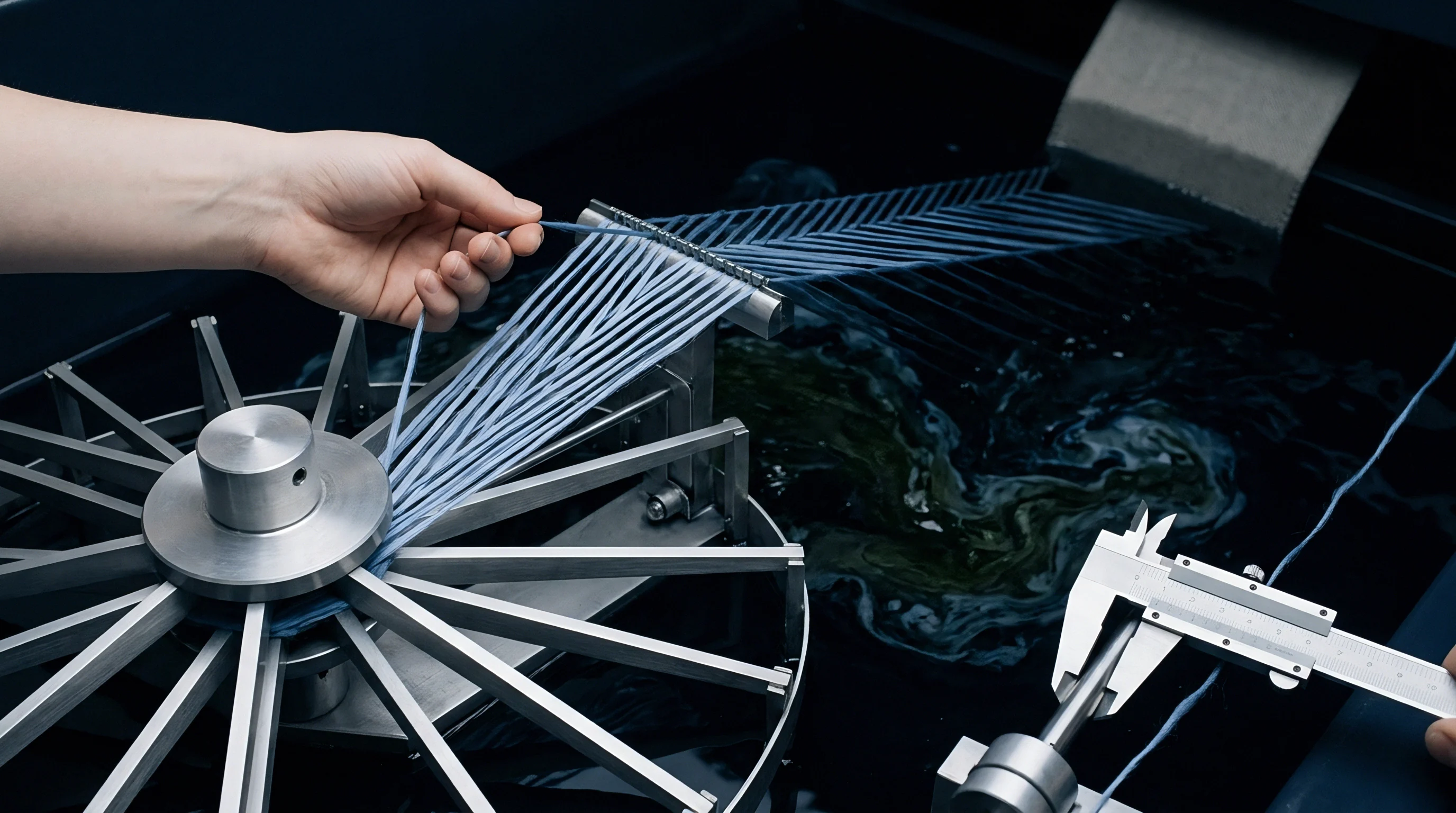
Excessive yarn tension during package depletion stretches synthetic polymers past their elastic yield limit. In polyester and polyamide continuous filaments, exceeding fifteen percent of ultimate tensile strain permanently alters molecular crystallinity. During piece dyeing, these overstretched yarns reject disperse or acid dyes relative to their normally tensioned neighbors, manifesting as prominent longitudinal streaks across the finished woven material.
Downstream sizing operations fail to rectify these differences. Stretched yarns absorb sizing starch or synthetic polymers differently due to altered surface pore geometry. Uneven sizing pick-up generates localized stiffness variations that trigger repeated yarn breakages inside the loom shedding zone.
| Depletion State | Tension Band (cN) | Residual Elongation (%) | CIELAB Delta E Shift | Loom Stops per 100k Picks |
|---|---|---|---|---|
| Full Package | 14 to 17 | 28.5 | 0.2 | 0.8 |
| Three Quarter | 17 to 20 | 28.2 | 0.3 | 0.9 |
| Half Depleted | 21 to 25 | 27.4 | 0.5 | 1.2 |
| Core Depleted | 28 to 36 | 24.1 | 1.4 | 3.6 |
| Bare Tube Spike | 38 to 48 | 19.8 | 2.8 | 8.4 |
Unevenly stretched synthetic filaments exhibit permanently altered molecular orientation that resists uniform disperse dye exhaustion during high-temperature jig processing.
Shedding Performance and Loom Stops
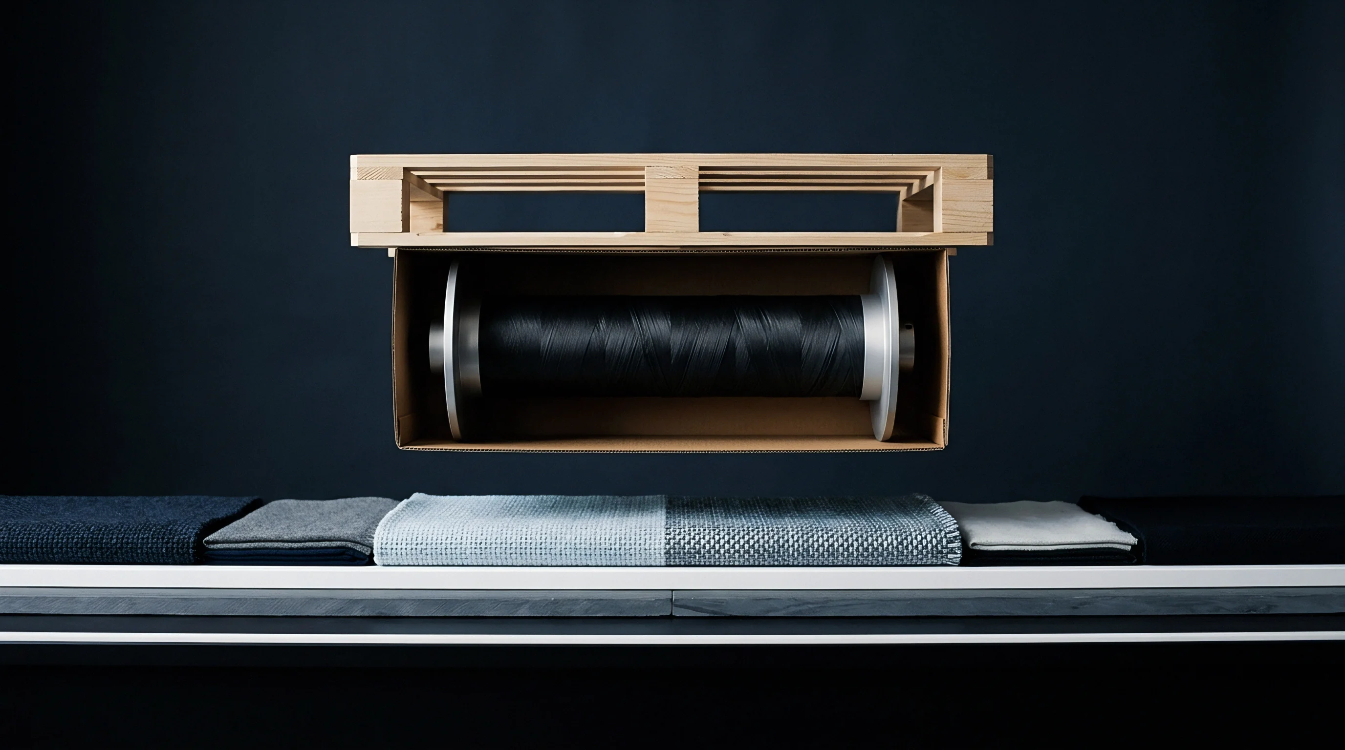
Unevenly wound warp sheets create sagging ends when the loom harness separates during air-jet weaving. When ends on the warp beam contain differing elastic recovery rates, the opening shed presents an irregular shed line. Slack ends generate loose warp loops.
Air-jet weft insertion picks catch on these loose filaments, causing immediate loom stops and pick misfires.
Braking torque drops over time. Warping beams produced with severe internal tension gradients suffer from barrel collapse or flange deflection during transport and storage. The compressive force of thousands of tightly wound outer layers crushes under-tensioned inner layers, destabilizing the entire beam geometry.
Ignoring package diameter tension escalation produces stripiness across finished piece-dyed textiles, leading directly to commercial rejection, unsalvageable off-shade inventories, and severe financial chargebacks from downstream apparel cutters.