Determining Maximum Allowable Hydrodynamic Nozzle Pressure in Jet Dyeing Machinery
Maximum allowable jet nozzle pressure depends on matching fluid shear velocity to fabric structural tension limits without exceeding filament yield thresholds.
Force
Mechanical fabric conveyance in closed-loop jet dyeing vessels depends on the kinetic propulsion generated by recirculating liquor passing through a constricted nozzle assembly. The circulating pump forces the dye liquor through a restricted internal diameter, generating a localized pressure differential that draws the endless fabric rope through the transport tube without mechanical drive rolls. Hydrodynamic pressure serves as the primary motive driver, overcoming internal vessel friction, liquor drag, and the weight of the wet fabric payload sitting in the storage J-box.
When hydrodynamic pressure stays within the structural tolerance of the yarn and knit structure, the fabric rope moves smoothly at speeds between 150 and 500 metres per minute. Overshooting the structural threshold transforms the fluid driver into a destructive mechanical shear force that distorts loop structures, shears delicate microfilaments, and creates irreversible surface abrasion.
Determining the safe operational boundary demands balancing fluid propulsion against the physical yield point of the textile substrate. Dynamic pressure exerted by the jet stream scales quadratically with fluid velocity through the orifice. A minor increase in pump motor frequency or a reduction in nozzle diameter drastically escalates the hydraulic kinetic energy applied directly to the wet fabric boundary layer.
Dyehouse operators often elevate nozzle pump output to cure fabric slippage, prevent vessel chokes, or force dense woven structures through narrow J-boxes. This hydraulic over-correction transfers excessive shear stress directly to the surface fibers, accelerating pilling, fuzzing, and seam degradation during long cycle times at elevated temperatures.
Fluid velocity through the jet tube needs to match fabric rope lineal speed to eliminate surface friction.
Mechanical degradation under excessive hydrodynamic delivery surfaces in distinct structural failure modes across different yarn constructions and fiber types. Identifying these physical defects on the inspection frame allows finishing engineers to trace bulk quality failures back to incorrect pump pressure parameters on the wet processing floor.
- Filament fibrillation manifests on synthetic microfilament structures when hydrodynamic fluid velocity strips outer fiber bundles, leaving fine white haze across dark shade runs.
- Loop distortion occurs in low-gauge single jersey knits when excess fluid thrust stretches wales unevenly, causing permanent width loss and skewing.
- Surface pilling develops on spun staple yarns as intense boundary layer turbulence entangles loose surface fibers into unyielding surface nep clusters.
- Rope marks form when high-velocity jet streams crush fabric folds tightly against the transport tube walls at temperatures above the polymer glass transition point.
- Seam failure happens when local hydrodynamic shock waves strike transverse joining seams, pulling sewing thread through compromised greige selvedges.
The exact threshold where motive force turns into structural destruction depends heavily on thermal conditions inside the vessel. As bath temperatures cross the glass transition point of synthetic fibers or soften hydrogen bonding in cellulosic networks, the fabric yield strength drops significantly. A nozzle pressure that proves perfectly benign at 40 degrees Celsius during the initial scouring pass can severely abrade the identical fabric load once the bath reaches a 130 degree Celsius polyester dyeing plateau.
The continuous interaction between thermal softening, fluid velocity, and mechanical rope tension creates a dynamic boundary that challenges standard dyehouse control protocols.
Orifice
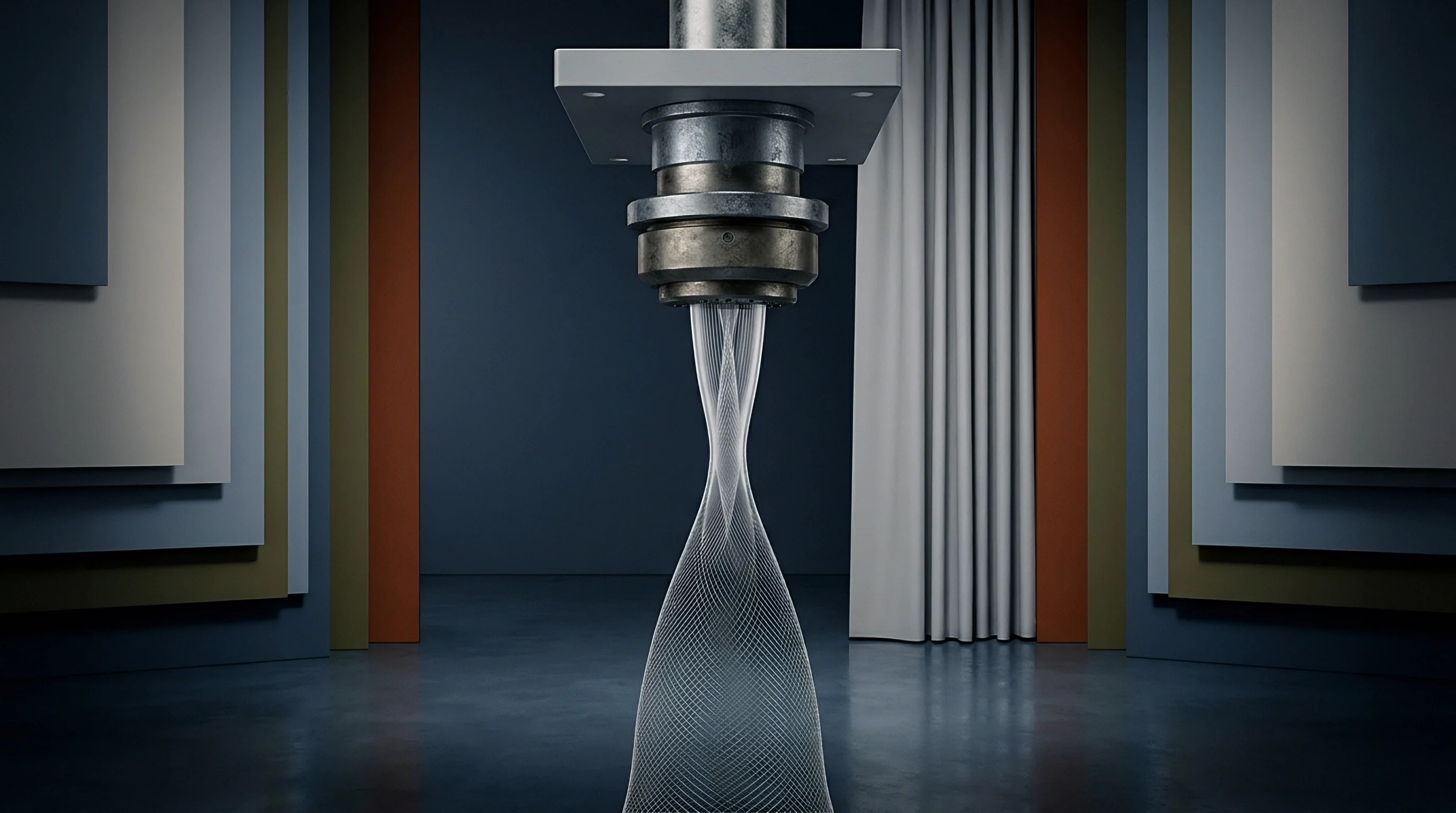
Fluid movement through the jet nozzle follows classic Venturi channel principles, converting static pressure generated by the main circulating pump into kinetic velocity at the point of narrowest constriction. The internal nozzle geometry consists of a converging inlet cone, a narrow circular throat, and a diverging transport pipe that guides the fabric rope toward the venturi tube. As liquid enters the constricted throat, cross-sectional flow area drops, driving fluid velocity upward while static hydraulic pressure falls proportionally.
The resulting pressure drop across the nozzle throat generates the suction force that pulls both dye liquor and the wet fabric rope smoothly through the main line.
Calculating the dynamic hydrodynamic pressure at the nozzle requires monitoring differential pressure (Δ P) across the jet assembly rather than relying solely on total pump discharge gauge readings. Total pump pressure accounts for line resistance throughout the entire piping loop, including heat exchanger pressure drops and valve restrictions. The true hydrodynamic force experienced by the fabric rope directly correlates to the localized pressure drop within the nozzle throat itself.
Measuring this localized differential pressure provides the engineering base needed to evaluate fluid velocity and mechanical drag factors against fabric structural limits.
At a 140 millimetre nozzle orifice diameter and 1200 litres per minute pump discharge, fluid dynamic pressure reaches 0.42 bar under atmospheric liquor temperature conditions.
Nozzle throat diameter acts as the primary mechanical variable controlling both liquor volume and fluid velocity for a given pump discharge setting. Selecting an oversized nozzle diameter reduces fluid velocity, leading to fabric rope deceleration, improper rope turnover, and localized shade blotchiness from insufficient liquor circulation. Choosing an undersized nozzle throat dramatically increases fluid velocity and hydrodynamic pressure, forcing the fabric rope through extreme shear forces while increasing vessel backpressure.
The table below details the physical relationship between nozzle orifice size, liquor flow rate, fluid velocity, and resulting dynamic hydrodynamic pressure in a standard 250-kilogram capacity jet dyeing port.
| Nozzle Orifice Diameter (mm) | Liquor Flow Rate (L/min) | Fluid Velocity (m/s) | Dynamic Hydrodynamic Pressure (bar) | Kinetic Energy Density (kJ/m³) |
|---|---|---|---|---|
| 80 | 800 | 2.65 | 0.35 | 35.1 |
| 100 | 1000 | 2.12 | 0.22 | 22.5 |
| 120 | 1200 | 1.77 | 0.16 | 15.6 |
| 140 | 1400 | 1.52 | 0.12 | 11.5 |
| 160 | 1600 | 1.33 | 0.09 | 8.8 |
| Data calculated assuming water density of 1000 kg/m³ at 20 degrees Celsius under ideal Venturi conditions without line drag loss. | ||||
Hydrodynamic pressure increases in direct proportion to liquor density and the square of fluid velocity through the throat. Because liquor velocity is inversely proportional to the square of the nozzle throat diameter, reducing orifice diameter by half increases fluid velocity fourfold and boosts kinetic dynamic pressure by sixteen times at a constant volumetric flow rate. Small changes in nozzle sizing produce dramatic shifts in the mechanical stress delivered to the moving fabric rope.
Fine adjustments to nozzle diameter allow exact matching of hydraulic propulsion to specific fabric weights and sensitivity profiles.
Matching nozzle selection to fabric rope volume demands evaluating nozzle fill ratio. The nozzle fill ratio represents the percentage of nozzle throat cross-sectional area occupied by the wet fabric rope. An optimal nozzle fill ratio ranges between 55 percent and 70 percent.
Operating below 50 percent fill ratio allows high-velocity fluid bypass, wasting pump energy and generating localized fluid turbulence that causes fabric tangles. Operating above 75 percent fill ratio chokes liquor flow, forcing total system pressure upward while starving the fabric rope of necessary boundary-layer fluid lubrication.
Optimal nozzle performance depends on maintaining a continuous fluid boundary layer around the moving fabric rope throughout the transport tube.
Substrate
Greige fabric construction establishes the fundamental mechanical boundary for maximum allowable hydrodynamic pressure during wet processing operations. Fiber composition, yarn structure, cover factor, gauge, and fabric weight per square metre dictate how much shear force a given textile build tolerates before displaying permanent damage. A heavy high-density woven cotton canvas withstands aggressive fluid velocities without structural distortion, whereas a loose light-gauge viscose jersey or a fine denier polyester filament knit requires delicate hydraulic handling to preserve structural integrity.
At What Velocity Does Surface Shear Produce Filament Fuzzing?
Microfilament synthetic yarns engineered for ultra-soft hand feel feature individual filament linear densities below 1.0 decitex. These delicate structures present extreme surface area exposure to high-velocity liquor streams inside the transport jet. When hydrodynamic pressure drives fluid velocity past 2.5 metres per second, boundary-layer drag forces pull individual filaments out of the low-twist yarn core.
This action creates widespread surface fuzzing and micro-pilling that ruins shade clarity and creates a dull, chalky appearance on finished synthetic piece-dyed goods.
Testing fabric dimensional stability under ISO 5077 after high-pressure jet exposure identifies permanent elongation caused by nozzle velocity exceeding structural yield strength.
Fabric structural density directly alters how fluid pressure translates into physical mechanical work across the web. High-gauge circular knits built from spun combed cotton yarns exhibit strong inter-loop friction that resists structural distortion, yet their exposed surface hairiness leaves them vulnerable to pill formation under hydraulic turbulence. Conversely, open warp knits feature low inter-yarn friction, allowing high-pressure fluid jets to push warp threads apart, causing permanent reed marks and dimensional bowing that cannot be corrected on the stenter frame.
The table below correlates common fabric greige constructions with their corresponding mechanical stress limits and maximum safe operating nozzle pressures.
| Fabric Construction Type | Yarn Component & Structure | Weight (GSM) | Maximum Safe Nozzle Pressure (bar) | Primary Mechanical Failure Signature |
|---|---|---|---|---|
| Single Jersey Knit | 100% Combed Cotton Spun 30s/1 | 140 | 0.18 | Surface pilling and loop distortion |
| Interlock Knit | 100% Micro-Polyester 0.8 dtex Filament | 220 | 0.12 | Filament shear and surface haze |
| French Terry Knit | 80/20 Cotton/Poly Spun Blend | 280 | 0.25 | Loop snagging and length extension |
| Plain Weave Poplin | 100% Combed Cotton Ring Spun | 110 | 0.30 | Seam slippage and crease marking |
| Twill Weave Workwear | 65/35 Poly/Cotton Ring Spun | 240 | 0.45 | Chafing along structural diagonal floats |
Evaluating new fabric constructions prior to commercial bulk processing requires a structured engineering verification approach. Standardizing the assessment process prevents costly floor rejections and ensures parameters match fabric performance requirements before committing production capacity.
- Calculate greige rope linear weight by converting fabric mass per square metre and open width dimensions into wet rope mass per linear metre under 100 percent liquor pickup conditions.
- Determine structural fiber yield point by reviewing dry tensile strength test results under ISO 13934-1 alongside bursting strength data under ISO 13938-1.
- Measure nozzle fill clearance by pulling a wet hand-sample rope through physical test nozzles to establish the exact volumetric fill ratio across target orifice diameters.
- Verify thermal softening limits by checking polymer glass transition thresholds against planned dyeing temperature profiles to anticipate structural vulnerability windows.
- Establish baseline pump limits by capping inverter frequency settings to restrict dynamic pressure generation below calculated substrate shear thresholds.
Ignoring substrate stress limits during high-speed jet processing leads directly to bulk lot rejections, severe weight loss from shed surface fibers, permanent dimensional shrinkage, and unrecoverable fabric deformation that destroys commercial margin.
Arithmetic
Quantifying maximum allowable hydrodynamic nozzle pressure (Pmax) requires integrating fluid dynamics equations with fabric mechanical resistance metrics. The baseline dynamic fluid pressure (Ph) generated inside the nozzle orifice is derived from fluid density (ρ) and average liquor velocity (vf) passing through the throat area:
Ph = frac12 · ρ · vf2
Liquor velocity (vf) is calculated directly from total volumetric pump delivery flow rate (Q) in cubic metres per second divided by the net open cross-sectional throat area (Anet). Net throat area represents total nozzle orifice area (Anozzle) minus the cross-sectional area occupied by the wet fabric rope (Afabric):
vf = fracQAnozzle – Afabric
To establish Pmax, the dynamic fluid pressure must not generate a total hydrodynamic drag force (Fdrag) that exceeds the maximum allowable surface shear tension (Tallow) of the specific fabric substrate. Hydrodynamic drag force relies on fluid velocity, wet fabric surface area inside the transport tube (S), and the dimensionless hydrodynamic drag coefficient (Cd) characteristic of the fabric surface topography:
Fdrag = frac12 · Cd · ρ · (vf – vr)2 · S
In this equation, vr represents the linear velocity of the moving fabric rope in metres per second. The relative velocity term (vf – vr) reflects the actual fluid slip occurring over the fabric boundary layer. Hydrodynamic shear stress increases rapidly when fluid slip expands, which occurs if fabric rope speed lags behind liquor flow velocity due to J-box friction or winch reel slippage.
Consider a working dyehouse scenario calculating Pmax for a 180 GSM 100% micro-polyester interlock knit processed in a high-temperature jet vessel. The process parameters are established as follows: target fabric rope speed (vr) sits at 4.0 m/s (240 m/min), wet liquor density (ρ) at 130 degrees Celsius equals 935 kg/m³, nozzle throat diameter (D) is 0.10 m (Anozzle = 0.00785 m2), and the wet fabric rope cross-sectional area (Afabric) measures 0.00285 m2. Laboratory tensile analysis confirms the fabric substrate experiences surface filament damage when hydrodynamic drag force exceeds 45 Newtons per linear metre of transport tube length.
The active nozzle tube length (L) measures 1.2 metres, establishing a total allowable shear force limit (Fmax) of 54 Newtons across the transport zone. The surface drag coefficient (Cd) for this interlock knit construction is established at 0.045, with a wet fabric surface contact area (S) of 0.48 m² inside the tube.
1. Calculate net cross-sectional flow area inside nozzle throat: Anet = 0.00785 – 0.00285 = 0.0050 m2.
2. Set maximum drag force equation equal to critical substrate limit: 54 = 0.5 · 0.045 · 935 · (vf – 4.0)2 · 0.48.
3. Simplify terms to solve for relative velocity slip: 54 = 10.098 · (vf – 4.0)2. Dividing 54 by 10.098 yields 5.347.
Taking the square root gives a maximum allowable slip velocity (vf – vr) of 2.31 m/s.
4. Determine maximum allowable fluid velocity: vf,max = 4.0 + 2.31 = 6.31 m/s.
5. Calculate maximum allowable volumetric flow rate: Qmax = vf,max · Anet = 6.31 · 0.0050 = 0.03155 m3/s, which translates to 1893 litres per minute.
6. Derive maximum allowable dynamic hydrodynamic nozzle pressure: Pmax = 0.5 · 935 · (6.31)2 = 18,612 Pascals, or 0.186 bar.
Equipment suppliers frequently claim their jet machines automatically equalize nozzle pressure across all fabric weight classes without manual adjustment. This operational claim oversimplifies fluid mechanical realities, as automated control valves adjust total volumetric pump output but cannot read the localized surface shear friction or filament yield points of specialized greige fabric constructions.
Diagnostics
Continuous operational verification of nozzle pressure parameters requires precision instrumentation installed directly at critical hydraulic junctions on the dyeing machine. Differential pressure transmitters mounted with digital sensing ports placed immediately upstream and downstream of the venturi assembly provide real-time differential pressure telemetry to the machine control unit. Integrating these differential sensors with variable frequency drives on the main circulating pump allows automated closed-loop regulation, holding dynamic fluid pressure within preset numerical boundaries throughout the complete wet processing cycle.
Diagnostic troubleshooting on the dyehouse floor relies on analyzing real-time pressure traces to identify operational anomalies before physical fabric damage occurs. Transient pressure spikes recorded during processing point directly to physical obstructions, fabric rope knots, or temporary choking within the transport pipe. A continuous gradual drift upward in differential pressure signals lint accumulation inside the nozzle throat heat-exchanger screen, whereas sudden drops in dynamic pressure indicate pump cavitation, low liquor levels, or severe air entrainment in the liquor circulation loop.
Differential pressure sensors mounted across the nozzle jet pipe reveal instantaneous pressure spikes during fabric seam pass-through.
Physical evidence on finished goods provides a clear diagnostic map connecting specific surface defects to exact hydraulic mechanical imbalances. Inspecting representative piece ends under standardized light box illumination allows wet processing engineers to differentiate between pressure-induced mechanical chafing and chemical fastness failure. The list below outlines the mandatory verification documentation required within a comprehensive dyehouse quality control dossier.
- Differential pressure calibration logs certifying annual two-point sensor accuracy checks against calibrated master manometer gauges.
- Substrate nozzle matching matrix documenting approved nozzle orifice sizes and maximum pressure caps for every active commercial fabric specification.
- Pump inverter frequency curves plotting motor power output against measured dynamic nozzle pressure across full thermal operating ranges.
- Rope velocity synchronization records verifying drive winch speed matches hydrodynamic liquor velocity within a five percent slip margin.
- Batch pressure telemetry files capturing millisecond-interval differential pressure readings throughout high-temperature processing steps.
Standard quality assurance guidelines specified under ISO 9001 wet processing additions mandate that high-temperature jet dyeing parameters stay within plus or minus five percent of validated target values, making real-time nozzle pressure tracking a mandatory contractual requirement for Tier 1 mill accreditation.

Expenditure
Hydrodynamic pressure choices directly govern the financial performance of wet processing operations by balancing energetic utility input against fabric yield loss and re-dyeing overhead. Operating main circulating pumps at unnecessarily elevated pressure levels escalates electrical power consumption significantly. Because centrifugal pump power demand scales with the cube of motor speed, running a pump at 0.40 bar dynamic nozzle pressure consumes over two times the kilowatt-hours required to process the identical lot at 0.20 bar.
Excess pressure converts directly into wasted heat energy inside the dye liquor, raising cooling water demand during thermal discharge phases.
Financial losses stemming from pressure-induced fabric damage extend far beyond simple utility waste. Fabric surface chafing, microfilament burst, and unrecoverable creasing force dyehouses to re-process degraded goods through chemical stripping, re-dyeing, or heavy softening passes. Severe structural damage leads to total batch rejection, forcing mills to pay full greige replacement costs alongside landed duty and freight penalties for missed delivery windows.
The table below illustrates the operational cost structure across three distinct dynamic nozzle pressure regimes in a high-capacity commercial dyehouse processing 500 tonnes of synthetic knit goods per month.
| Operating Pressure Regime | Mean Dynamic Pressure (bar) | Specific Energy Draw (kWh/kg Cloth) | First-Time Right Quality Yield (%) | Total Finished Processing Cost (USD/m) |
|---|---|---|---|---|
| Low Pressure (Under-driven) | 0.08 – 0.12 | 0.18 | 88.5 | 0.48 |
| Optimized Hydraulic Balance | 0.15 – 0.22 | 0.24 | 98.2 | 0.36 |
| High Pressure (Over-driven) | 0.35 – 0.50 | 0.42 | 81.0 | 0.62 |
Operating below minimum required hydrodynamic thresholds creates a distinct financial drag through extended cycle times and shade unlevelness. Insufficient pressure slows fabric rope turnover, dropping liquor-to-fabric contact cycles below acceptable kinetic thresholds. Operators must then lengthen processing times to achieve shade levelness, increasing steam consumption and cutting vessel throughput by up to twenty percent.
Achieving maximum financial margin requires establishing the precise operational window where hydrodynamic transport forces cleanly move the fabric rope while preserving substrate surface integrity.