Dynamic Load Cell Balancing for Continuous Twill Dyeing Lines
Real-time load cell balancing across continuous twill dyeing lines prevents warp elongation, listing color variance, and twill diagonal skew.
Tension
Continuous pad-dyeing ranges running heavy cotton twills subject the running web to asymmetric longitudinal forces across wet padder and dry can zones. Woven twills ~ especially 3/1 Z-twills weighing between 250 and 420 grams per square metre ~ exhibit directional elasticity when pulled end-to-end. As dry greige cloth enters the padding mangle, liquor absorption increases fabric mass by 65 percent to 85 percent depending on immersion time and nip pressure.
That sudden weight gain alters web momentum, raising the force needed to accelerate guide rollers downstream in the wet range.
Mounting full-bridge strain-gauge sensors on cantilevered idler roll journals tracks web force in real time across critical transition zones. In continuous pad-steam runs, tension shifts distort thread alignment whenever linear pull strays from target limits. Heavy, wet cloth dragging across uncompensated rollers displaces warp yarns, causing dense streaks and permanent width loss.
Tracking tension at the padder entry, steamer inlet, wash boxes, and dry cans isolates local drag before the fabric permanently deforms.
Running force on a 320 gsm cotton twill inside the steam chamber stays below 180 N/m at 75 percent liquor pickup to prevent structural distortion.
Target tension boundaries depend on fabric mass, weave structure, and moisture levels. The table below lists baseline load thresholds across a continuous pad-steam line processing 300 gsm 3/1 cotton twill at a nominal speed of 50 metres per minute.
| Process Zone | Fabric State | Nominal Speed (m/min) | Web Mass (gsm) | Target Line Force (N/m) | Permissible Variance (%) |
|---|---|---|---|---|---|
| Padder Entry | Conditioned Greige | 50.0 | 300 | 220 | ± 3.0 |
| Infra-Red Pre-Dryer | Wet Padded (70% pickup) | 50.1 | 510 | 140 | ± 2.5 |
| Steam Chamber Inlet | Semi-Dried (35% pickup) | 50.3 | 405 | 160 | ± 2.0 |
| Wash Box Array | Fully Saturated | 49.8 | 545 | 190 | ± 4.0 |
| Cylinder Dryer Feeder | Damp (45% pickup) | 49.5 | 435 | 210 | ± 3.5 |
| Data measured on 3/1 Z-twill 100% combed cotton fabric, 160 cm finished width, standard atmosphere conditioning (ISO 139). | |||||
Unbalanced tension through wet processing zones permanently stretches warp yarns, producing severe edge-to-center shade listing that renders whole production lots unusable on garment cutting tables.
Roller
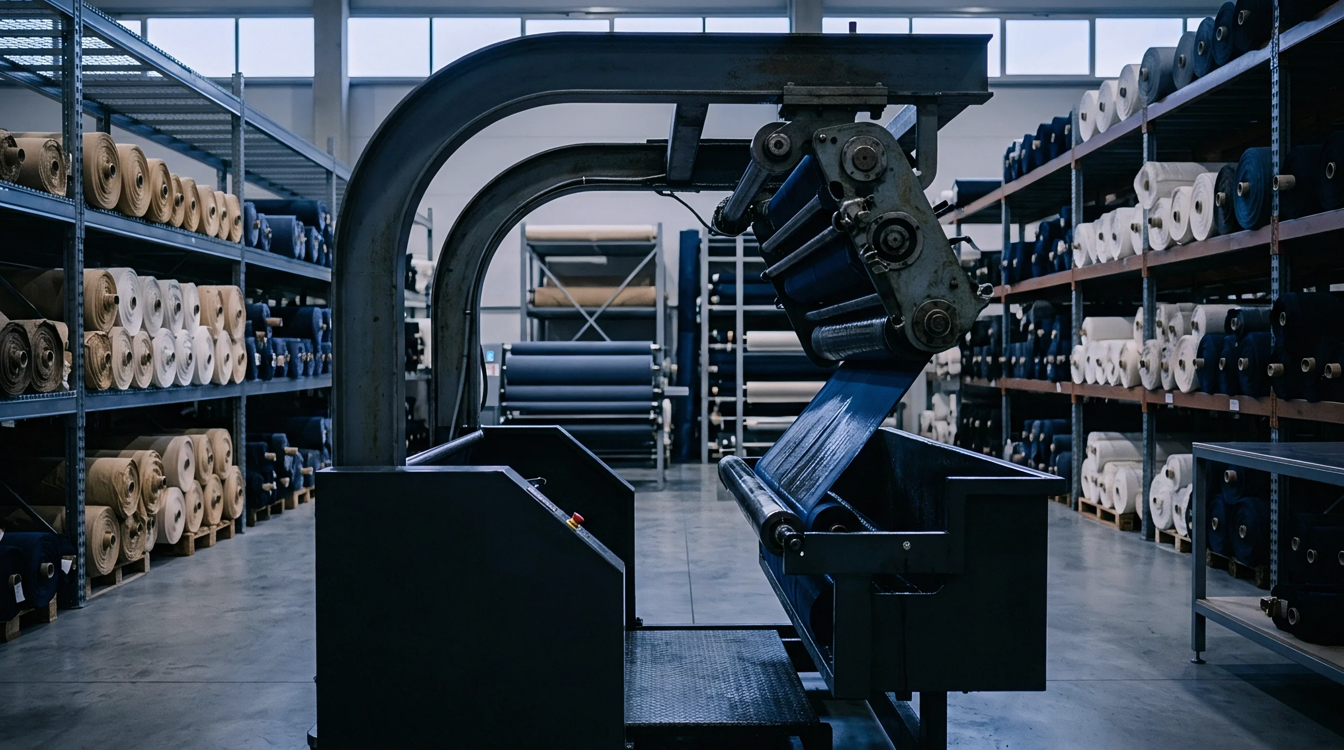
Idler assemblies, rubber squeeze nips, and dancer pivot arms transfer web forces directly to strain-gauge mounting blocks. Mechanical imperfections in these rotating parts distort raw signals before drive algorithms process them. Shaft misalignment or worn bearings introduce periodic resistance spikes that resemble true tension shifts, throwing off downstream motor controllers.
Rubber-covered mangle rolls introduce further mechanical variables during long runs. High nip pressures that flex core shafts push load distribution outward toward bearing housings. Heat from dye baths or steam chambers softens or expands rubber sleeves, changing effective roll diameters and breaking velocity synchronization across sections.
- Eccentric Bearing Wear ~ Uneven bearing friction on guide rolls produces low-frequency voltage oscillations that resemble web drag spikes.
- Squeeze Roll Deflection ~ Nip pressures over 40 N per millimetre flex the core shaft, shifting loads to the roll journals and skewing zero-point calibration.
- Thermal Sleeve Expansion ~ Heat from 102 degrees Celsius steam chambers expands rubber coverings unevenly, altering effective roll radius and section speed synchronization.
- Dancer Arm Hysteresis ~ Friction in pneumatic dancer pivots dampens mechanical response, delaying load cell signal registration.
Signal instability is frequently blamed on floor vibrations rather than uncompensated mechanical runout in the rollers.
Strain
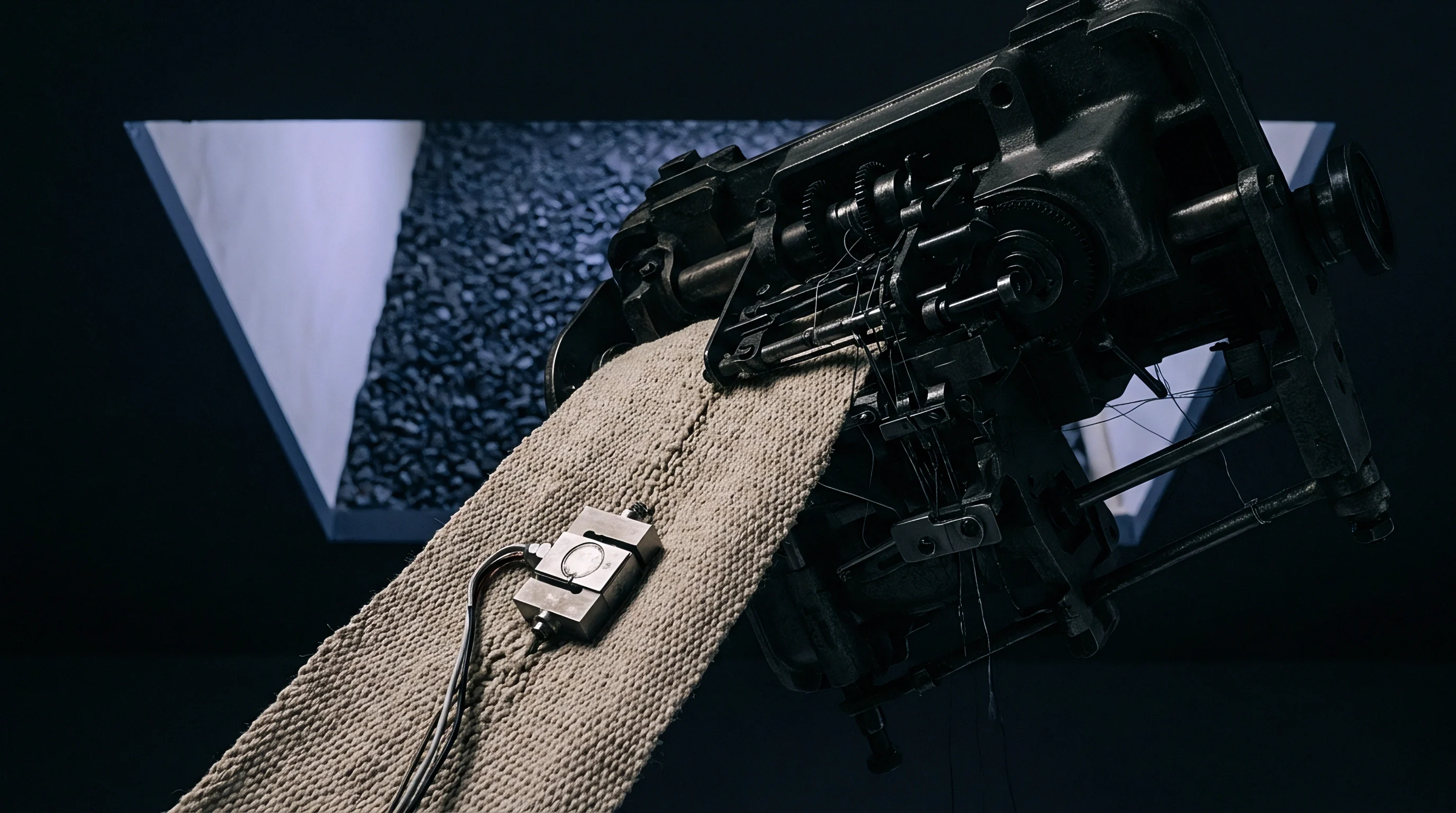
Transducer signals pass through signal-conditioning hardware before reaching the main drive controller. The faint millivolt output from load cells picks up interference easily from nearby variable-frequency drives, high-voltage heating banks, and ground loops. Industrial signal conditioners convert raw bridge voltages into isolated 0-10 V or 4-20 mA control signals using differential instrumentation amplifiers with high common-mode rejection.
What Causes Dynamic Signal Noise in Continuous Dyeing?
Eccentric shaft bearings create cyclic voltage spikes that mask true web tension. On high-speed lines where drives generate heavy electrical noise, separating real tension trends requires active hardware and software filtering. Low-pass Butterworth filters set to a 2 Hz cutoff strip out high-frequency mechanical vibration while preserving genuine tension shifts caused by moisture changes or drive mismatches.
Digital notch filters target specific shaft rotation frequencies, eliminating harmonics without slowing down control loop response.
Stabilizing high-speed web control relies on filtering mechanical roll vibration before issuing drive correction commands.
Careful parameter setup allows signal hardware to suppress transient mechanical noise without dulling sensitivity to real web drag changes. Table 2 outlines filter configurations and sampling rates across key dyeing zones.
| Processing Zone | Filter Configuration | Cutoff Frequency (Hz) | Sampling Rate (Hz) | Primary Noise Source Target | Drive Loop Latency (ms) |
|---|---|---|---|---|---|
| Padder Feed Zone | Digital Low-Pass | 1.5 | 100 | Unwind Stand Mechanical Runout | 15 |
| Liquor Mangle Nip | Hardware Notch | 3.0 | 500 | Squeeze Roll Shaft Harmonic | 8 |
| Steam Box Interior | Dual-Stage Butterworth | 2.0 | 250 | Vapor Turbulence & Fan Vibration | 12 |
| Wash Tank Array | Moving Average Filter | 1.0 | 50 | Fluid Drag Wave Oscillation | 25 |
Standard purchase contracts citing ISO 13934-1 cap post-processing fabric elongation at two percent of greige dimensions, setting a firm baseline limit for automated web control systems.
Feedback
Closed-loop drive systems process load-transducer voltages to trim variable-frequency motor speeds. The main PLC calculates error by comparing live web tension against recipe setpoints. When wet fabric hits the washing section, longitudinal shrinkage increases drag on section motors.
If the controller fails to adjust inter-section speed ratios immediately, web strain exceeds yield limits, altering twill density and leading to uneven dye extraction.
Consider a continuous pad-steam line running a 40,000-metre lot of 300 gsm 3/1 cotton twill at 50.0 metres per minute. Inside the steamer, hydro-expansion lengthens the fabric by 1.6 percent. Web tension at the entry load cell drops from the 200 N/m setpoint down to 145 N/m.
The controller converts this 55 N/m negative error into a trim command, raising the steamer section speed ratio from 1.000 to 1.016. That acceleration restores web force to 200 N/m within 420 milliseconds, maintaining fabric alignment.
When cloth leaves the steamer and enters cold washing, thermal shock and rinsing trigger a 2.4 percent warp contraction. Tension jumps from 200 N/m to 290 N/m at the first wash tank roll. Transducers send this spike to the inverter, slowing the first wash box motor by 2.4 percent to a speed ratio of 0.976 relative to the steamer section.
Trimming speed ratios across wet transitions holds web tension steady despite continuous dimensional movement.
Color consistency specifications referencing ISO 105-J03 reject bulk fabric lots whenever speed variations introduce shade deviations greater than a Delta E of 0.8.
Trimming motor speed ratios step-by-step through successive wet zones preserves fabric structure far better than applying heavy torque corrections at the exit dryer.
Skew
Woven twills carry a structural bias that causes diagonal twisting under end-to-end pull. Right-hand 3/1 Z-twills twist toward the direction of the main diagonal under load, while left-hand S-twills pull in the opposite lateral direction. When a continuous line subjects twill cloth to high web tension, this bias converts longitudinal pull into lateral web drift.
Dual load cells mounted on opposite journal ends detect side-to-side tension imbalance. A higher load reading on the operator side indicates off-center tracking or severe twill spirality. Correcting these lateral imbalances requires precise load cell calibration, proper roll alignment, and integrated guiding hardware.
- Clear all mechanical tare weights from the sensing assembly and calibrate both amplifier channels to zero volts without web contact.
- Thread dry cotton twill precisely down the centerline of the guide frame to balance lateral load across both sensing journals.
- Hang calibrated test masses on the left and right sensor bearings independently to match gain multipliers across both measurement channels.
- Run the empty line at 40 metres per minute to capture baseline roll eccentricity waveforms for the active noise-cancellation table.
Correcting structural skew in heavy twills requires pairing differential load monitoring with active mechanical web guides.
- Asymmetrical Load Cell Delta ~ Tension differences between drive and operator sides exceeding seven percent signal active twill spirality distortion.
- Bowed Expander Roller Angle ~ Curved expander bars placed before pad nips soften center-to-selvedge tension gradients driven by fabric contraction.
- Steamer Entry Alignment ~ Optical weft straighteners feed data directly into load cell control loops to correct bias before dyestuff fixes.
Whether automated drive balancing can fully isolate twill structural torque from mechanical shaft wear at speeds over eighty metres per minute remains an open question in plant engineering.
Ledger
Capital investment in continuous load balancing directly affects second-quality defect rates. Unbalanced lines running heavy cotton twills face repeated quality failures ~ most notably listing shade variations, twill skewing, and out-of-spec post-wash shrinkage. Quantitative financial analysis underscores the clear economic return of multi-zone load balancing systems on continuous ranges.
Take a continuous dyeing operation running 500,000 metres of 300 gsm 3/1 cotton twill annually at a base fabric cost of $3.20 per metre. An uncalibrated line relying on manual speed trims shows a second-quality downgrade rate of 4.2 percent from tension listing and warp elongation. Installing a closed-loop multi-zone load cell network drops that downgrade rate to 0.6 percent by keeping web strain uniform through every wet and thermal zone.
Second-quality fabric carries a price penalty of $1.50 per metre on wholesale markets. Cutting defect rates by 3.6 percent saves 18,000 metres from downgrade, preserving $27,000 in revenue per 500,000-metre run.
Re-dyeing rejected continuous-dyed twill doubles thermal energy consumption and consumes half the gross margin of the dyehouse contract.
Operational metrics highlight the financial advantage of automated tension balancing over conventional fixed-speed dyeing ranges.
| Operating Parameter | Uncompensated Line | Load Cell Balanced Line | Economic Impact per 500,000 Metres |
|---|---|---|---|
| Second-Quality Scrap Rate (%) | 4.2 | 0.6 | 18,000 Metres Saved from Downgrade |
| Shade Re-Dye Rate (%) | 2.8 | 0.3 | 12,500 Metres Re-Dye Energy Savings |
| Warp Elongation Defect Rate (%) | 1.9 | 0.1 | $14,400 Claim Liability Avoided |
| Average Line Velocity (m/min) | 38.0 | 52.0 | 36.8% Production Throughput Gain |
| Annual Maintenance Cost ($) | 12,500 | 18,200 | $5,700 Net Sensor Calibration Expense |
Investments in multi-zone strain gauge arrays pay back within eight months on heavy twill runs. Precise speed trimming eliminates mechanical strain peaks, preserves warp density specs, and stabilizes shade quality across long production shifts.