Quantifying Structural Yarn Tension Variance across Multi-Beam Creels in High-Speed Warping
Creel position frictional differential and package diameter decay drive warp tension variance, requiring dynamic compensation to limit loom stoppage rates.
Kinematics
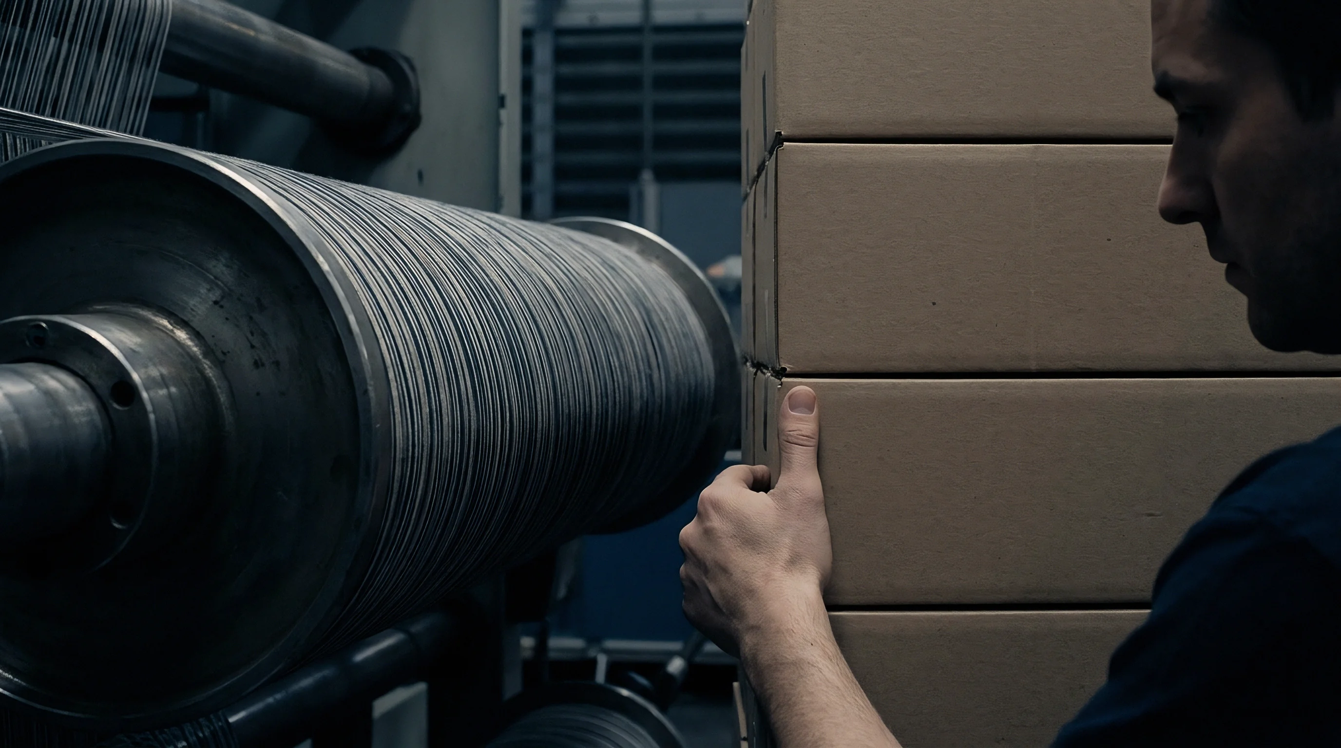
At thread speeds between 800 and 1,200 metres per minute, modern warping creels create unavoidable tension differences across individual yarn ends. The yarn encounters aerodynamic drag along open threadlines, ballooning forces from centrifugal action, and cumulative friction across guide surfaces as it leaves each package. Ends from the rear tiers of a 600-position V-creel travel up to 12 metres farther through ceramic eyelets and ambient air than those at the front, creating distinct static and dynamic friction imbalances before the web ever reaches the lease reed or presser roller.
Package geometry complicates the problem. Drawing yarn off a full bobbin with an outer diameter of 280 millimetres generates minimal ballooning tension because the rotational frequency stays low and the lift angles remain wide. As the package empties to a bare 55-millimetre tube, rotational speed climbs by more than five times at constant warping speeds.
That higher rotational speed widens the balloon diameter, triggering dynamic tension spikes as yarn rubs against neighboring package shoulders and creel framework rods.
Frictional contact follows standard capstan behavior, scaling exponentially with the total angle of wrap over stationary guides. A threadline crossing five synthetic aluminum oxide pins with an aggregate wrap angle of 2.1 radians multiplies tension according to specific yarn-guide interactions. Waxed combed cotton typically exhibits a friction coefficient near 0.18 against polished ceramic, while raw synthetic filament ranges from 0.30 to 0.45 depending on spin-finish oil levels and pin surface roughness.
Peak tension spikes during high-speed package unwinding routinely exceed baseline running tension by more than eighty percent as unwinding package diameters approach bare tubes.
On fine-count yarns at high speeds, atmospheric drag along open threadlines introduces its own baseline tension gradient. Longer runs from the back of the creel generate boundary-layer air resistance that lifts running tension regardless of mechanical settings. Between package exhaustion and distance-induced drag, the creel develops a multi-dimensional tension profile where outer, rear packages run consistently tighter than inner, front positions.
The following measurement table quantifies typical running tension variations observed across a standard 540-end V-shaped warping creel running a 20 tex combed cotton yarn at a uniform beam winding velocity of 1,000 metres per minute.
| Creel Position | Distance to Comb (m) | Average Static Tension (cN) | Dynamic Peak Tension (cN) | Coefficient of Variation (%) |
|---|---|---|---|---|
| Front Tier (Inner Column) | 2.50 | 12.1 | 16.8 | 6.2 |
| Middle Tier (Mid Column) | 6.80 | 14.4 | 21.3 | 8.9 |
| Rear Tier (Outer Column) | 11.20 | 17.8 | 27.5 | 12.4 |
| Rear Tier (Bare Bobbin Core) | 11.20 | 22.3 | 36.1 | 16.8 |
Deflection rods and anti-ballooning rings help damp the severe orbital swings that occur during bare-tube unwinding. These passive guides convert large rotational motions into minor vibrations, stabilizing the yarn before it enters the tension units, though they add contact points that increase total running tension. Whether passive damping alone can balance asymmetric creel layouts without causing excessive surface abrasion on fine yarns remains an open question.
Draft
Balancing threadline forces across the creel requires dedicated tension controls at every package position. Traditional disc units use gravity weights or spring pressure to pinch yarn between polished plates, but spring designs collect lint and develop surface grooves that cause disc flutter, often increasing tension variation rather than damping it. Centralized pneumatic or electromagnetic units compensate automatically, adjusting clamping pressure from encoder feedback as beam speed changes or package diameters shrink.

Mechanical Tensioner Calibration and Maintenance Sequence
Maintaining tension uniformity across high-density creels demands systematic inspection and adjustment protocols. The checklist below establishes key operational checks required to keep mechanical friction devices within allowable tolerances.
- Ceramic Eyelet Surface Inspection checking all guide pins for microscopic grooves or chip defects using optical magnification to eliminate localized yarn fraying.
- Dead-Weight Washer Cleaning removing oil film, lint buildup, and size residue from disc contacts using volatile non-residue solvent sprays.
- Spring Calibration Standardizing adjusting mechanical spring tensioners against a calibrated electronic hand-held tensiometer under static yarn line loading conditions.
- Pneumatic Pressure Manifold Verification testing pressure drop equality along air feed lines from front to rear creel columns using digital manometer taps.
- Self-Cleaning Disc Rotation Check verifying that running yarn causes slow rotational movement of tension discs to prevent localized wear tracks.
Pulling yarn beyond its yield point causes permanent plastic deformation. Tensile stretch changes yarn crimp, cuts into residual elongation at break, and shifts linear density under ISO 2060 test conditions. In staple spun yarns, exceeding four percent permanent elongation causes core fibers to slip, reducing breaking tenacity during ISO 13934 strip tests.
In synthetic continuous filaments, tension variations during warping alter latent thermal shrinkage, appearing later as tight ends or streakiness in dyed and finished goods.
Uncompensated mechanical tension differentials across warping creel tiers generate permanent structural yarn elongation before the warp sheet reaches the sizing slasher.
Consider a practical engineering calculation involving a high-speed warping operation running 600 ends of 15 tex 100 percent polyester continuous filament yarn at 1,100 metres per minute. Assume baseline tension targets sit at 12.0 centinewtons per end, with an allowable tolerance of plus or minus 0.5 centinewtons. Physical measurements reveal rear-tier unwinding tension averaging 16.5 centinewtons due to cumulative ceramic eyelet friction and 11.5 metres of threadline drag.
This 4.5 centinewton excess force represents a 37.5 percent overshoot above target operational parameters.
Polyester filament running at 16.5 centinewtons experiences 1.8 percent elongation prior to beam winding. When wound onto the beam under that load, the yarn stores elastic energy. Once relaxed, ends from the rear creel retain a permanent set of 0.6 percent over front-tier ends that ran at 12.0 centinewtons.
Over a 1,000-metre section, that strain difference compounds to a 6-metre physical length disparity, producing visible warp bands across high-density fabrics.
Properly staged tensioning equalizes extension across all ends, matching the elastic energy stored on the beam barrel. In practice, setting front-tier mechanical tensioners tighter and rear tiers looser balances the friction accumulated over varying path lengths by the time ends reach the comb.
Telemetry
Tracking dynamic tension swings across the warp sheet requires continuous online data capture. Hand-held three-roller tensiometers take useful single-end static readings, but they miss high-frequency transients during acceleration, high-speed running, and emergency stops. Modern installations place piezo-resistive or strain-gauge sensors at comb entries or tensioner exits, logging data at rates up to 1,000 Hertz to catch the brief tension spikes that cause yarn breaks or hidden yield defects.
Does on Line Tensiometry Eliminate High Speed Tension Spikes?
Continuous monitoring provides operational visibility, but sensors alone cannot suppress physical force spikes without immediate closed-loop actuator feedback. High-speed data loggers highlight localized spikes caused by slubs, tail-knot passages, or loose package wraps. When dynamic tension monitoring connects directly to automated pneumatic creel regulators, central system logic adjusts zone manifold pressures within milliseconds, damping transient force waves before yarns hit the warping beam.
Closed-loop control drastically narrows the coefficient of variation across the entire warp sheet.
Statistical output from online sensors forms the basis for beam grading. Tension coefficient of variation across the sheet gives a direct read on beam uniformity: keeping the CV below five percent ensures consistent beam density and smooth payoff at the slasher, while values above ten percent correlate with frequent yarn breaks on air-jet looms.
The sequence outlined below details the operational trial steps required to conduct a thorough multi-point tension audit on a production warping machine.
- Mount high-frequency load cell tensiometers on sixteen representative threadline paths distributed across top, bottom, front, and rear creel zones.
- Calibrate sensor outputs to zero force with threadlines completely slackened using digital calibration gauge blocks.
- Accelerate the warping machine to the target speed of 1,000 metres per minute while recording tension data at a minimum sample frequency of 500 Hertz.
- Log dynamic baseline tension, peak force spikes, and standard deviation over a continuous 2,000-metre warping run.
- Initiate a controlled emergency stop from full running speed to record peak deceleration force spikes across all monitored creel positions.
- Export raw tension time-series datasets into statistical analysis software to compute localized variation coefficients and identify outlier threadlines.
The standard reference table below correlates warp tension variation coefficients with operational downstream weaving performance metrics across standard cotton and synthetic blend warp qualities.
| Warp Tension CV Range (%) | Warp Yarn Break Rate per 10^5 Ends | Slasher Lapper Frequency | Grey Fabric Defect Rate (%) |
|---|---|---|---|
| 3.0 – 4.9 | 0.8 | Negligible | 0.12 |
| 5.0 – 7.9 | 2.1 | Low | 0.45 |
| 8.0 – 11.9 | 5.4 | Moderate | 1.28 |
| 12.0 – 16.0 | 11.7 | High | 3.85 |
Ignoring real-time tension telemetry leads directly to soft beam shoulders, irregular size pickup at the slasher, frequent loom stops, and high defect rates at the grey inspection table.
Sizing
Tension variations locked in during warping carry straight into wet sizing. When unevenly tensioned beams unwind into the size box, loose ends drop lower into the liquor while tight ends ride hard over immersion rollers. This disparity alters immersion time and nip pressure distribution at the squeeze rolls, leading to irregular starch or synthetic size penetration.
Tightly pulled ends pick up less size, leaving them under-protected against abrasive loom action.
Uneven size pickup alters yarn stiffness, hairiness encapsulation, and tensile modulus. Slack ends that absorb excess size dry into stiff, brittle yarns with poor residual elasticity. Ends carrying too little size shed fibers against the loom reed, forming lint balls that trigger warp-stop sensors on air-jet and rapier looms.
Across the whole sheet, variations in chemical pickup also disrupt dye uptake during subsequent beam or piece dyeing.
Warp beam ends running under differential tension exhibit uneven wet size pickup, generating localized structural variations that cannot be corrected during fabric finishing.
In finishing and dyeing, size pickup discrepancies show up as shade bands and streaks. Dyes react unevenly across yarns with different thermal-mechanical histories and coating weights; ends that ran loose during warping hold more sizing, which restricts dye liquor diffusion into the fiber matrix. The resulting fabric exhibits warp stripes that fail shade uniformity standards under ISO 105-J03 color evaluation testing.
| Beam Position | Yarn Creel Tension (cN) | Size Pickup Variation (%) | Warp Beam Density (g/cm3) | Dye Levelness Delta E |
|---|---|---|---|---|
| Position 1 (Inner Creel Ends) | 11.8 | +2.4 | 0.52 | 0.35 |
| Position 2 (Middle Creel Ends) | 14.2 | -0.8 | 0.56 | 0.62 |
| Position 3 (Outer Creel Ends) | 18.1 | -3.9 | 0.61 | 1.45 |
Failure modes triggered by uneven beam tensions during slasher processing extend well past simple shade variation. The list below outlines structural fabric defects directly caused by warp tension differentials passing through wet sizing operations.
- Warp Stripe Formation displaying narrow longitudinal bands of lighter or darker shade across finished dyed fabric due to localized dye uptake variation.
- Slasher Lapper Development occurring when slack yarn ends overlap adjacent ends on drying cylinders, causing broken ends and machine stoppages.
- Uneven Beam Hardness Profiles producing soft beam edges that collapse during transport or firm centers that trap moisture during drying cycles.
- Warp End Rollover causing individual warp ends to cross over neighbor ends during comb insertion, leading to severe shedding failures during weaving shed opening.
Multi-cylinder slashers cannot correct existing warp beam tension differences through zone-controlled wet draft drives alone. Slasher draft zones stretch the sheet as a whole, preserving end-to-end tension disparities through the drying section and onto the loom beam.
Discrepancy
Greige fabric supply contracts establish clear thresholds for warp defects, loom stops, and tensile limits. When sourcing high-density fabrics, warp tension standards must be written directly into mill purchase orders. When greige goods show repeating warp bands or exceed contract stop allowances, liability traces back to warping logs.
Without continuous telemetry data, mills often attribute the faults to yarn lot inconsistency or sizing mix adjustments.
Assessing the cost of uncorrected creel tension means weighing greige fabric downgrades against operational overhead. In a room of 100 air-jet looms weaving high-density bottom-weights, excess warp breaks can pull operating efficiency from 92 percent down to 81 percent. That drop translates directly to lost linear production, longer delivery lead times, and higher labor expense for operators drawing in broken ends.
Purchase Order Technical Annexure Requirements
Preventing commercial disputes requires establishing detailed technical metrics within purchasing contracts before issuing bulk production approvals. The checklist below identifies document elements necessary to enforce creel tension quality standards across supply partners.
- Maximum Allowable Tension Variation Coefficient setting strict limits on warp end tension standard deviation across all creel zones.
- Mandatory On-Line Telemetry Logging requiring mills to maintain digital tension logs for every warped beam set within the production batch.
- Package Unwinding Limit Standard defining minimum bobbin core weight thresholds before creel package changeover to prevent bare tube tension spikes.
- Warp Beam Hardness Distribution Limits establishing acceptable durometer reading ranges across the beam width under ASTM D2256 guidelines.
When greige shipments show warp band defects exceeding 1.5 points per hundred linear metres under four-point inspection standards, standard commercial contract clauses require the supplier to cover re-inspection costs, fabric downgrades, and air freight charges for replacement yardage.