Cover Factor Calculation Impact on Fluid Penetration Rates in Woven Fabrics
Accurate cover factor calculation defines interthread pore hydraulic radius, predicting hydrostatic penetration pressure and capillary wicking velocity in woven barriers.
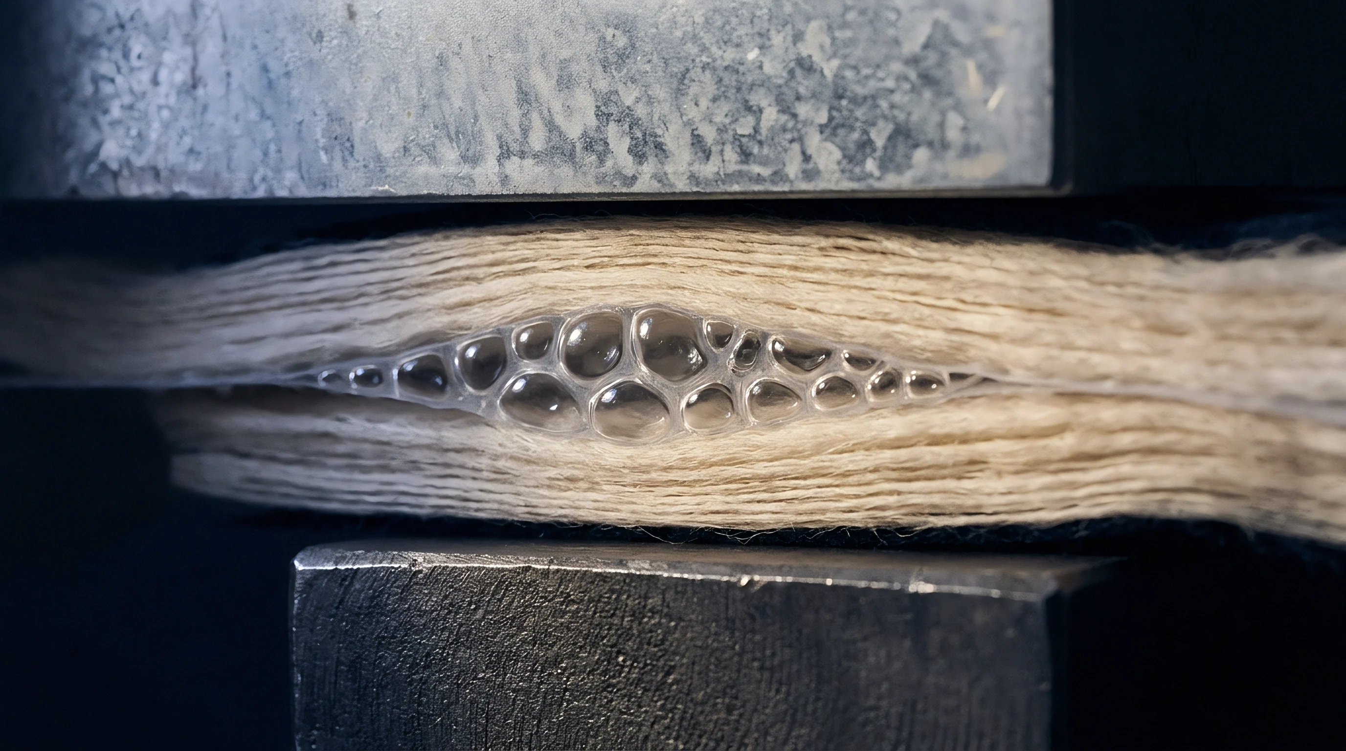

Arithmetic
Mathematical modeling of woven structures establishes the relationship between yarn dimensions and the void spaces between threads. F. T. Peirce established classical fabric geometry in 1937 by defining cover factor as the ratio of yarn width to yarn spacing. In the English system, warp cover factor K1 and weft cover factor K2 derive from ends per inch n1 or picks per inch n2 divided by the square root of the English cotton yarn count N1 or N2.
Imperial cover factor formulas express yarn diameter as proportional to the reciprocal of the square root of yarn count, assuming a specific yarn volume density. Metric calculations convert thread count to threads per centimetre and yarn linear density to tex, expressing cover factor K as threads per centimetre multiplied by the square root of tex divided by ten. Fractional cover factor C represents the actual surface area occupied by yarns relative to total fabric surface area, computed as C = C1 + C2 – (C1 × C2), where C1 is warp fractional cover and C2 is weft fractional cover.
Fractional density values vary from 0.60 in loose gauze structures to 0.95 in dense technical oxford fabrics.

Fractional Density and Metric Cover Formulations
Calculations using classical Peirce formulas assume circular yarn cross-sections and constant fiber packing density throughout the yarn body. Real continuous filament and spun staple yarns flatten during weaving under warp tension and beat-up forces. Elliptical yarn deformation increases yarn width parallel to the fabric plane while reducing cross-sectional height perpendicular to the plane.
Modified fractional cover formulas incorporate a flattening coefficient, adjusting effective yarn diameter upward by eight to fifteen percent depending on fiber modulus and weave structure. Higher yarn compaction increases total fractional cover while drastically compressing the cross-sectional area of interstitial pores between warp and weft intersections. When calculating fractional cover for high-density barriers, neglecting yarn flattening leads to an underestimation of true surface cover by six to twelve percent, generating false predictions of fluid penetration channels.
| Model Type | Mathematical Formulation | Assumed Cross-Section | Calculated Fractional Cover (20 Tex, 30 ends/cm) | Predicted Interpore Radius ( micrometres ) |
|---|---|---|---|---|
| Peirce Imperial | K = Ends per Inch / sqrt(Cotton Count) | Circular | 0.72 | 18.4 |
| Metric Standard | K = (Threads/cm x sqrt(Tex)) / 10 | Circular | 0.74 | 16.8 |
| Modified Fractional | C = C1 + C2 – (C1 x C2) with Flattening Factor | Elliptic / Racetrack | 0.83 | 10.2 |
| Compact Fiber Void | C_adj = C x (1 – Yarn Porosity) | Deformed Micro-bundle | 0.89 | 6.5 |
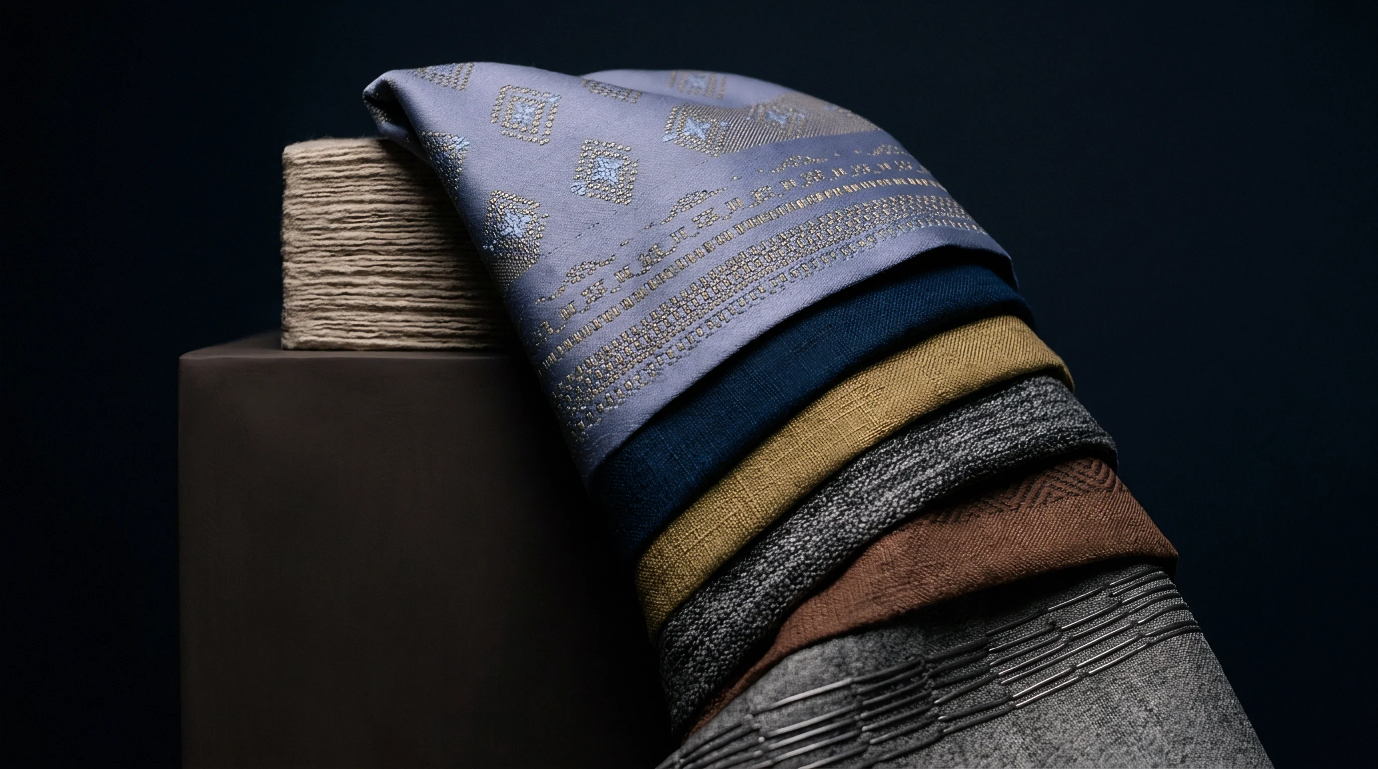
Structural Geometry of Interthread Channels
Cross-sectional spaces between adjacent threads create micro-channels that govern liquid transport across the substrate. Calculating pore dimensions requires evaluating both the interthread pore area between adjacent parallel yarns and the inter-fiber micro-pores within individual yarn structures. Liquid penetration under hydraulic head occurs primarily through interthread pores, as these channels present significantly lower hydrodynamic resistance than inter-fiber voids.
Pore hydraulic radius rh connects directly to total fractional cover through the relationship rh = d / (4 × (C / (1 – C))), where d represents average yarn diameter. As fractional cover increases from 0.75 to 0.90, pore hydraulic radius contracts non-linearly, dropping by over sixty-five percent. This exponential collapse of interstitial channel diameter forms the primary physical barrier against fluid flow.
Calculating cover factor using off-the-loom greige thread counts instead of finished fabric thread counts creates fundamental errors in fluid transport predictions. Weaving contraction, scouring relaxation, and stenter heat-setting alter ends and picks per centimetre by five to eighteen percent. A plain weave fabric measured at 28 ends per centimetre in the loom-state may finish at 32 ends per centimetre after wet relaxation.
This dimensional change elevates fractional cover from 0.78 to 0.86, cutting calculated pore hydraulic radius in half and reducing theoretical fluid flux by a factor of sixteen under viscous flow equations. Calculating cover factor without accounting for post-loom shrinkage guarantees invalid fluid penetration models.

Mesh
Pore network dimensions dictate how liquid moves through open void spaces under gravitational or external forces. Liquid penetration through woven structures follows capillary flow principles described by the Lucas-Washburn equation and Darcy’s Law for porous media. Hydraulic pressure needed to force liquid through an open interthread channel depends inversely on pore radius and directly on liquid surface tension multiplied by the cosine of the contact angle.
Small variations in calculated cover factor yield exponential changes in hydrostatic resistance because breakthrough pressure scales with the reciprocal of maximum pore radius. Higher cover factors minimize maximum pore diameter, raising the energetic threshold required for fluid entry.

Capillary Pressure and Hydrostatic Resistance Thresholds
Hydrostatic head performance measured under ISO 811 or AATCC 127 quantifies the pressure at which water penetrates a fabric face. Capillary pressure Pc within an interthread void follows the Young-Laplace relationship Pc = (2 × γ × costhη) / r, where γ represents water surface tension (72.8 mN/m at 20 degrees Celsius), thη is the contact angle between water and fiber, and r is the effective pore radius. When calculated cover factor increases from 0.80 to 0.92, maximum pore radius contracts from 25 micrometres to 4 micrometres.
This radial contraction increases theoretical capillary resistance pressure from 5.8 kPa (59 cm H2O) to 36.4 kPa (371 cm H2O) for an untreated fiber matrix displaying a 0-degree contact angle, proving that structural density alone generates substantial liquid resistance prior to chemical treatment.
Increasing cover factor by ten percent reduces maximum interthread pore diameter by over fifty percent, quadrupling the hydrostatic pressure required for fluid breakthrough.

Does Yarns Flattening Alter Pore Size Distribution?
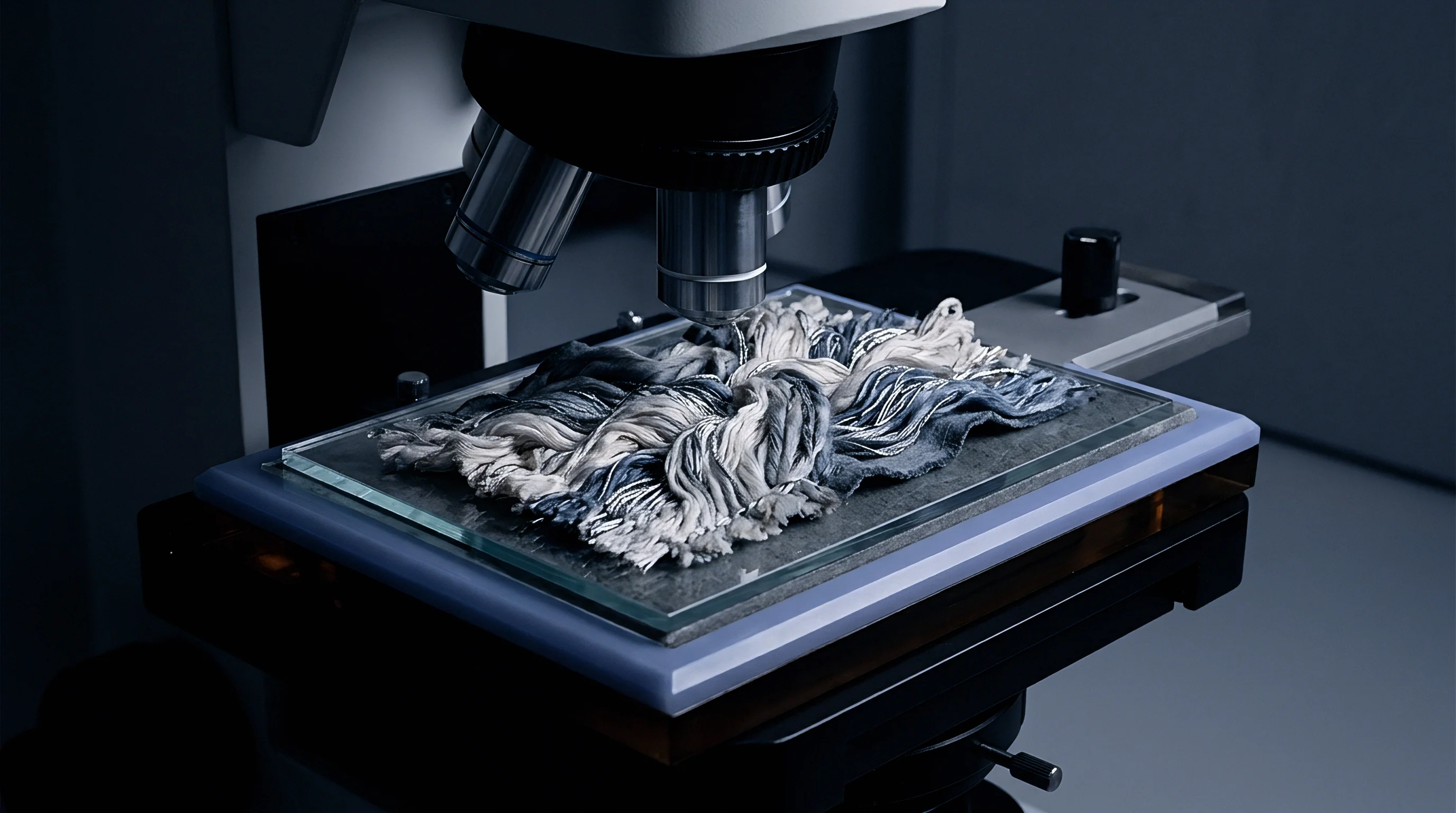
Mechanical compression during weaving deforms circular yarn profiles into elliptical or racetrack shapes. Yarn flattening under high beat-up force narrows the spacing between adjacent warp and weft yarns, narrowing the maximum pore size distribution measured by capillary flow porometry under ASTM F316. Unflattened circular yarn assumptions yield theoretical pore diameters thirty to forty percent larger than actual measured pore diameters on finished woven fabrics.
Elliptical deformation closes wide interstitial gaps, creating uniform micro-pores across the fabric plane. This structural uniformity prevents localized fluid breakthrough caused by isolated oversized pores, elevating overall fabric hydrostatic resistance.
- Mount the pre-conditioned fabric sample securely into the capillary flow porometer testing cell using an O-ring seal to prevent edge leakage.
- Wet the sample completely with a low surface tension fluid (porofil wetting liquid with surface tension of 16 dynes/cm) to fill all interstitial pores.
- Apply compressed air at incrementally increasing pressure steps, recording displacement gas flow rates through cleared pores as capillary pressure overcomes wetting liquid surface tension.
- Calculate maximum pore diameter (bubble point) and mean flow pore diameter using the Young-Laplace equation based on recorded pressure-flow curves.
- Compare measured mean pore diameter against theoretical pore hydraulic radius calculated from metric cover factor equations to quantify structural flattening factors.
Selecting an incorrect cover factor calculation model during fabric design causes field failure in fluid barrier applications. Specifying a fabric build based on basic Peirce cover factor equations overestimates pore size, leading developers to mandate higher chemical DWR loading than structurally necessary. Excess chemical finishes increase stiff hand feel, reduce tear strength, and elevate production costs unnecessarily.
Fabric specifiers who rely on raw greige thread counts without adjusting for wet processing finishing shrinkages fail ISO 811 hydrostatic pressure audits on finished garments, forcing costly mill re-runs or shipment rejections.

Swelling
Fibre absorption of liquid alters internal channel dimensions within seconds of initial fluid contact. Hydrophilic fibers like cotton, viscose, and linen absorb water directly into their crystalline and amorphous regions, expanding in diameter by fourteen to forty-five percent while experiencing minimal axial elongation. Synthetic hydrophobic fibers like polyester and polyamide exhibit negligible volume changes under water exposure, absorbing under one to four percent water weight.
Dynamic fiber expansion during fluid transit reduces interthread void spaces in real time, progressively restricting fluid flux through high-density woven fabrics.

Fibre Hydration and Pore Closure Kinetics
Cellulosic materials expand transversely upon absorbing liquid molecules, reducing interthread channel volume. Cotton yarn in a dense plain weave expands in cross-sectional area upon liquid contact, driving interthread pore hydraulic radius toward zero during continuous exposure. Dynamic wicking calculations must account for time-dependent pore area reduction A(t) = A0 × (1 – Sf × (1 – exp(-t / τ))), where A0 is initial dry pore area, Sf is fiber swell capacity factor, t is wicking time, and τ is hydration rate constant.
In a cotton canvas with an initial cover factor of 0.85, fiber hydration closes open void spaces within sixty seconds, turning a porous matrix into a self-sealing fluid barrier.
At 20 degrees Celsius and 65 percent relative humidity, a 100 percent cotton plain weave displaying a calculated cover factor of 0.86 exhibits a 14 percent interthread pore area reduction within 120 seconds of initial liquid contact.

Surfactant Influence on Contact Angle Shifts
Chemical additives in testing liquids or residual processing wetters lower liquid surface tension, accelerating fluid penetration through tight gaps. Detergents, dye auxiliaries, and wetting agents reduce water surface tension from 72.8 mN/m to under 30 mN/m. This surface tension drop lowers the capillary pressure threshold required for liquid penetration according to the Young-Laplace equation.
High cover factor constructions mitigate surfactant-driven fluid penetration by physically restricting channel radius. Even when chemical contact angle falls near zero, interthread pores under 3 micrometres require significant external dynamic impact pressure for liquid to penetrate through the substrate.
- Capillary Wicking Breakthrough occurs when low-surface-tension liquids enter interthread voids despite high chemical repellent ratings, driven by mechanical pressure or surface surfactant contamination.
- Dynamic Impact Penetration manifests when high-velocity water droplets strike high-cover fabrics, overcoming static capillary pressure thresholds through kinetic energy transfer.
- Hydraulic Channel Dilation develops when fluid pressure deforms high-density woven structures, forcing warp and weft yarns apart to widen micro-pore diameters during sustained fluid exposure.
- Pinhole Leakage Defect arises from local variations in yarn linear density or reed marks, creating isolated low-cover zones that leak water under low hydrostatic pressure.
High-density cotton goods frequently resist initial liquid penetration during wet processing, often attributed to yarn sizing or synthetic waxes. However, dense cover factor geometry physically blocks liquid liquor entry into internal yarn bundles faster than chemical repellents do. Scouring liquor cannot enter interthread voids when physical channel diameters drop below 5 micrometres, preventing complete desizing and chemical preparation across the bulk run.
Stenter
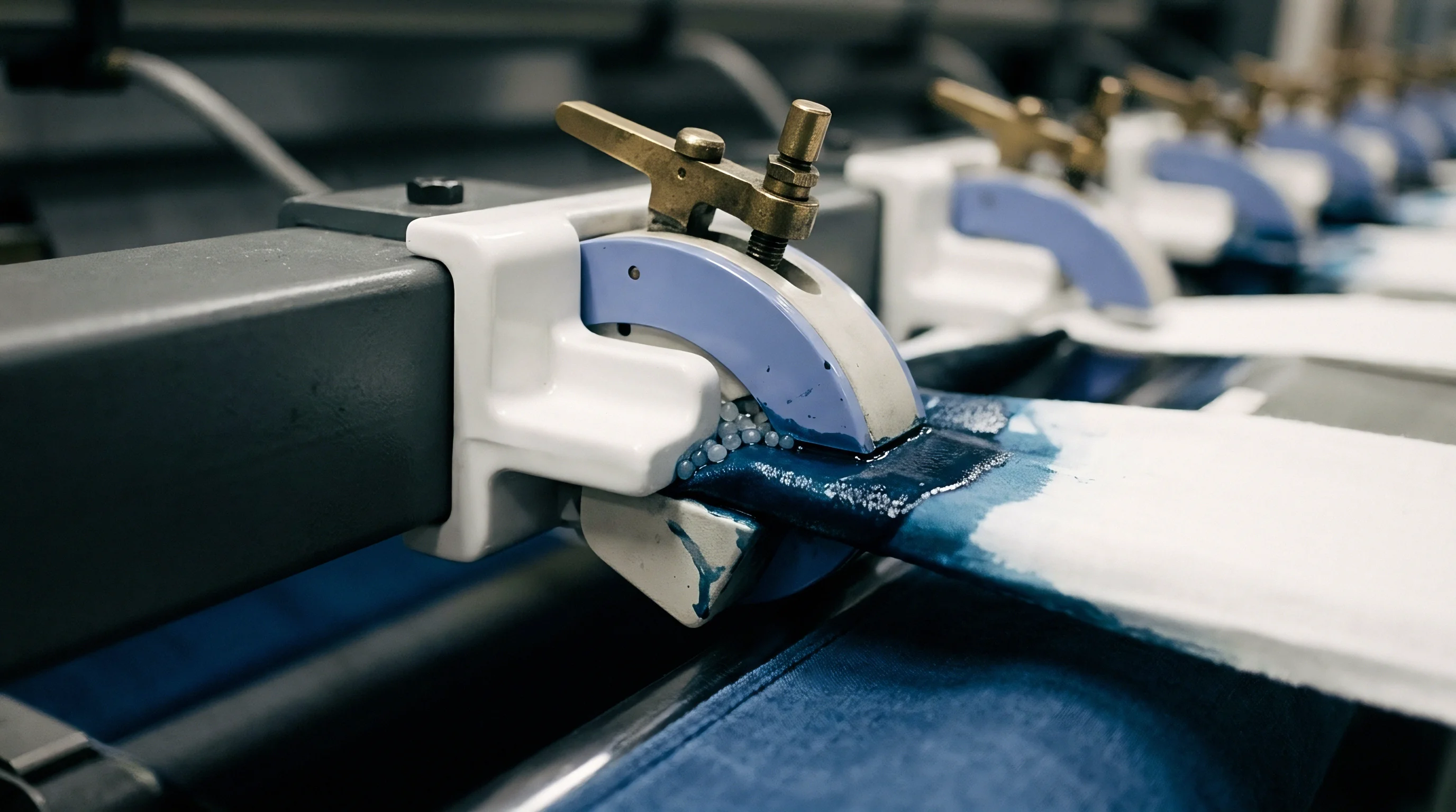
Mechanical finishing equipment alters thread counts and yarn packing factors on dry goods. Scouring, bleaching, dyeing, heat setting, and calendering permanently modify warp and weft density from loom-state values. Stenter frames apply longitudinal overfeed and transverse tension, adjusting ends and picks per centimetre while fixing synthetic fiber lattice structures.
Calendering subjects fabric to heavy mechanical pressure between steel and synthetic rollers, flattening yarn cross-sections and compacting fabric thickness. These finishing operations drastically raise actual fabric cover factor above theoretical greige calculations, fundamentally altering final fluid penetration rates.
Thermomechanical Shrinkage and Greige Density Shifts
Relieving weaving tensions during scouring and heat treatment causes fabric dimensions to contract, elevating yarn density per unit length. Polyamide and polyester woven barrier fabrics undergo five to fifteen percent thermal shrinkage during stenter processing at 180 to 210 degrees Celsius. Shrinkage elevates warp ends per centimetre from 40 to 45 and weft picks per centimetre from 32 to 36 in a micro-denier weave.
This post-loom compaction increases fractional cover factor from 0.81 to 0.91, reducing mean flow pore diameter from 12.5 micrometres down to 3.8 micrometres and raising ISO 811 hydrostatic head ratings from 8 kPa to over 35 kPa without additional DWR coating application.
| Processing Stage | Warp Sett (ends/cm) | Weft Sett (picks/cm) | Fractional Cover Factor | Mean Pore Diameter ( micrometres ) | ISO 811 Hydrostatic Head ( kPa ) |
|---|---|---|---|---|---|
| Loom-State Greige | 38.0 | 30.0 | 0.79 | 15.2 | 4.2 |
| Scoured & Relaxed | 41.5 | 33.0 | 0.85 | 8.6 | 12.5 |
| Stenter Heat-Set | 43.0 | 35.0 | 0.88 | 5.4 | 22.0 |
| Schreiner Calendered | 43.2 | 35.2 | 0.93 | 2.1 | 48.5 |
Hydrophobic Finishes and Surface Energy Boundaries
Fluorocarbon and silicone applications modify substrate free energy without physically altering thread counts. C8 fluorocarbon, C6 fluorocarbon, and fluorine-free DWR finishes deposit micro-thin polymer films over fiber surfaces, altering fiber water contact angles from 0 degrees (wetting) up to 110 to 130 degrees (repellent). The effective resistance to fluid penetration depends on the combined effect of high cover factor geometry and DWR surface energy modification.
High cover factor structural density acts as a physical force multiplier for chemical finishes: a low-cover fabric (0.70 fractional cover) treated with C6 DWR yields an ISO 811 rating of 10 kPa, whereas a high-cover fabric (0.90 fractional cover) treated with the exact same DWR concentration achieves 50 kPa hydrostatic resistance.
Standard purchasing specifications require finished woven barrier goods to meet ISO 811 hydrostatic pressure thresholds on five distinct test points per roll, with zero individual test specimen falling more than ten percent below the agreed lot mean.
- Audit Greige to Finished Sett Ratio by comparing loom reed plans against post-stenter thread counts to confirm total finishing shrinkage matches calculated cover factor targets.
- Verify Calender Pressure Parameters including roller temperature, nip pressure, and line speed to ensure consistent yarn flattening without crushing fiber tensile properties.
- Quantify DWR Add-On Percentage using wet pick-up measurement or dry add-on weight analysis to isolate structural cover factor barrier effects from chemical repellency.
- Test Hydrostatic Head Pre- and Post-Wash according to ISO 6330 laundering methods to verify that cover factor compression survives repeated wash relaxation cycles.
Standard sales contracts for technical barrier fabrics mandate that finished fabric thread count tolerances must remain within plus or minus two percent of the approved master specification, with failure to maintain density targets releasing buyers from bulk acceptance obligations.

Outlay
Financial commitments in high-density technical textiles grow sharply as cover factor targets approach theoretical packing limits. Pushing warp ends and weft picks per centimetre higher forces weaving mills to operate rapier and air-jet looms at reduced speeds to prevent yarn chafing, warp end breaks, and reed damage. Weaving a high-density down-proof taffeta with a 0.92 cover factor costs significantly more per metre than a standard 0.80 cover factor liner fabric due to lower loom efficiencies and elevated yarn quality demands.

Yield Losses from High Sett Looms
Inserting maximum pick counts reduces air-jet and rapier weaving speeds, increasing per-metre conversion charges. High-density warp setts increase yarn friction within the drop wires, heald wires, and reed blades. Running a 20-tex polyester warp at 48 ends per centimetre drops loom efficiency from ninety-two percent to seventy-eight percent compared to a 36 ends per centimetre construction.
Stopped loom time increases defect rates per hundred running metres, generating off-quality second-grade goods that reduce mill margins. Converting high-density grey goods requires premium combed staple yarns or high-tenacity filament yarns capable of withstanding extreme beat-up tension without fraying.
Operating air-jet looms at reduced RPM to insert high pick densities increases fabric weaving conversion cost per linear metre by twenty-five to forty percent compared to standard commodity densities.
Cost Mechanics of Water Barrier Compliance
Meeting ISO 811 hydrostatic pressure standards without liquid-proof coatings demands fine yarns and tight loom settings. To demonstrate the economics, evaluate a sourcing comparison between a coated medium-cover fabric and an uncoated high-cover ultra-dense fabric designed for liquid barrier performance. Sourcing a 100 percent polyester 75-denier plain weave with a cover factor of 0.78 coated with 20 g/m2 of polyurethane provides high water resistance (100 kPa hydrostatic head) at a fabric weight of 110 g/m2 and a landed material outlay of 2.10 USD per metre.
Developing an uncoated barrier using micro-denier 30-denier yarns woven at a cover factor of 0.92 achieves a hydrostatic head of 35 kPa at a weight of 55 g/m2, but demands a landed material outlay of 4.35 USD per metre.
Sourcing technical fluid barrier fabrics requires balancing yarn linear density, cover factor formulas, wet finishing contraction, and weaving costs against final fluid penetration requirements. The structural cover factor calculation provides the core engineering metric connecting greige thread counts to real-world hydrostatic performance, enabling textile engineers to optimize density parameters before committing financial capital to bulk production runs.