Hydrodynamic Nozzle Pressure Limits in Jet Dyeing Machinery
Nozzle pressure limits in jet dyeing protect sensitive fiber strands from kinetic liquid shear abrasion while maintaining stable fabric propulsion speeds.
Pressure
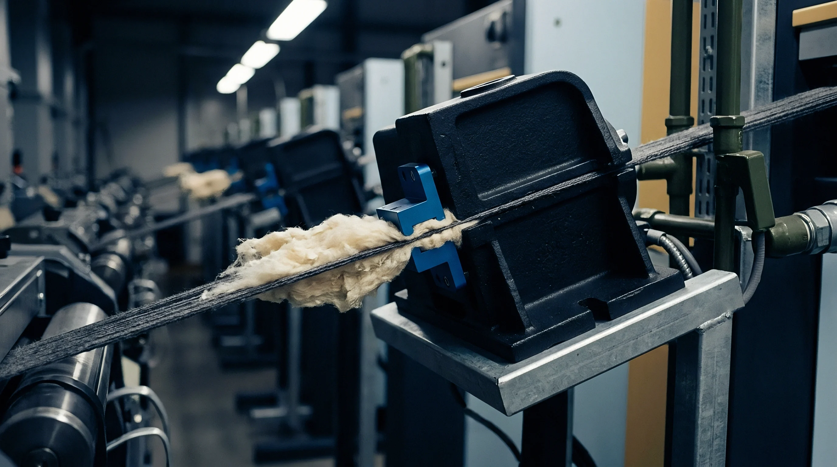
Hydrodynamic forces inside high-temperature jet dyeing vessels dictate both fabric transport speed and surface boundary friction. Fluid velocity leaving the nozzle pipe transfers kinetic momentum to pull the rope through the main chamber tube without mechanical reel traction. When dynamic fluid forces exceed the tensile limit of the textile structure, yarn displacement occurs instantly.
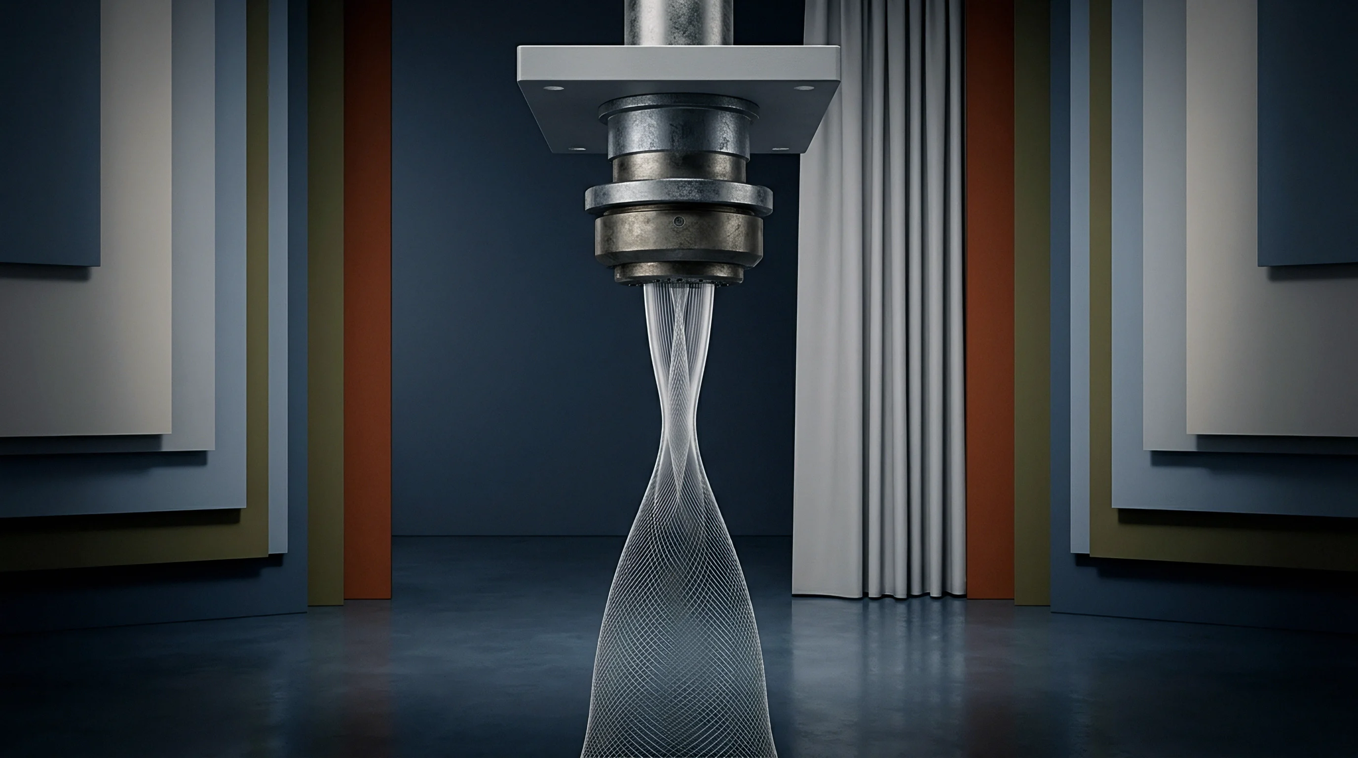
High pump output creates a differential head across the venturi throat, driving fluid through small orifices at speeds exceeding twenty metres per second. Modern soft-flow and high-flow jet machines balance liquor volume against hydraulic energy to maintain circulation while protecting yarn integrity.
Liquor circulation within an enclosed vessel relies on total dynamic head generated by centrifugal pumps. Increased impeller rotation raises liquid velocity, converting static bath head into dynamic fluid pressure at the nozzle gap. Heavy woven constructions with high areal weight demand substantial dynamic hydraulic pressure to overcome bath drag inside the accumulator pipe.
Lightweight spun yarns and microfilament synthetic knits deteriorate under high hydraulic friction. Excess hydraulic propulsion distorts stitch geometry, inducing permanent surface abrasion along the rope axis.
Dynamic hydrodynamics across the transport line vary with liquor viscosity and chemical bath loading. Surfactants, leveling agents, and salt additions alter fluid density and surface tension, modifying the kinetic force exerted on the moving rope. High temperature processing at one hundred thirty degrees Celsius drops bath viscosity significantly, increasing fluid velocity at identical pump frequencies.
Operators controlling high-pressure jets balance thermal expansion parameters against nozzle pressure limits to preserve fabric surface appearance.
Standard ISO 13934 tensile performance drops markedly when nozzle pressure surpasses two bar during jet processing of spun rayon blends.
Hydraulic force requirements directly reflect fabric weight, tube diameter, and total rope length. A light polyamide circular knit requires minimal dynamic pressure to reach continuous circulation speeds of three hundred metres per minute. A heavy cotton terry loop construction demands maximum volume output at lower kinetic velocities to prevent rope blockage inside the transport vessel.
Pressure limits serve as protective boundaries that isolate delicate spun fibers from destructive hydrodynamic shear stress.
Excessive fluid acceleration inside the transport ring causes localized fiber shear, stripping filament bundles, rupturing delicate stitch walls, and producing irreversible surface hairiness across bulk lots.
Venturi
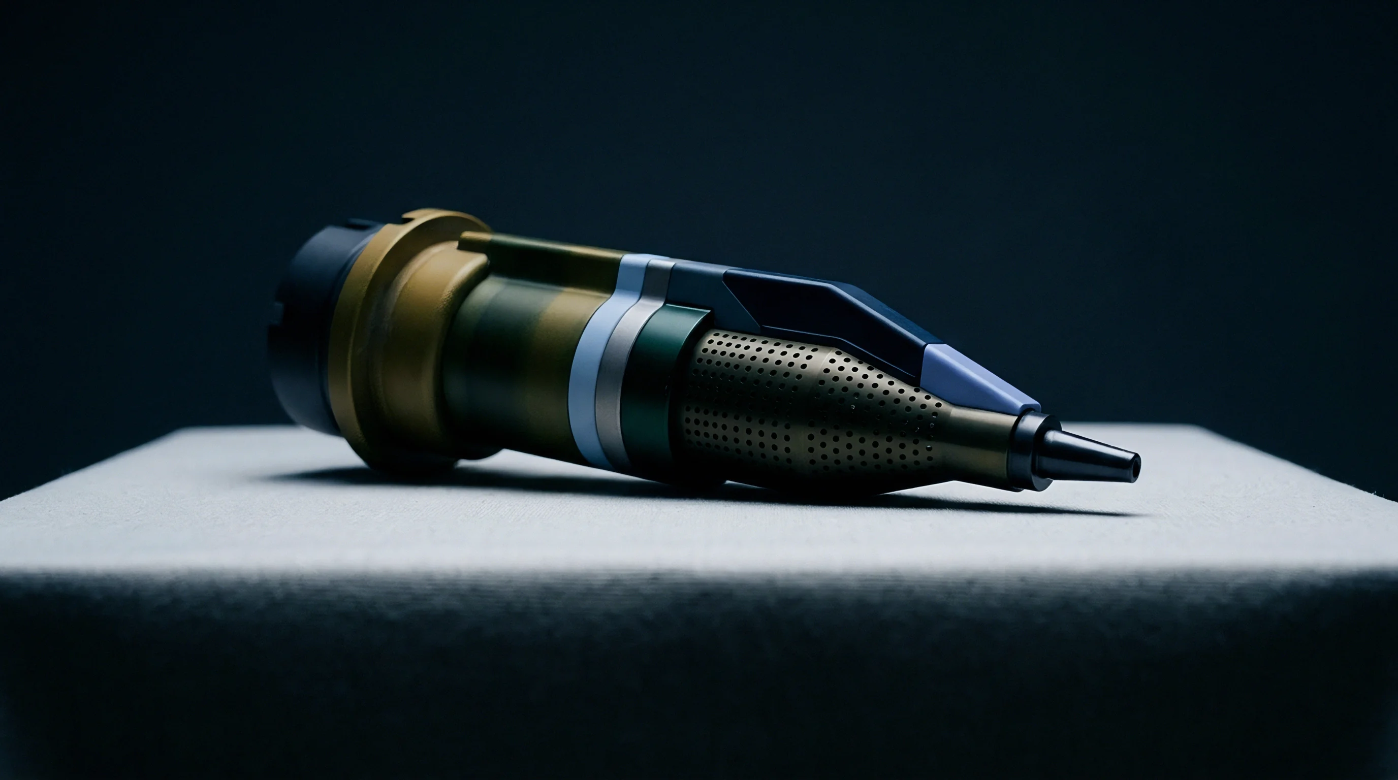
Nozzle throat cross-sectional geometry dictates the physical trade-off between liquid volumetric flow and jet velocity. Fluid entering a tapered constriction speeds up while static head drops according to Bernoulli principles. Variable gap nozzles allow operators to adjust the ring aperture manually or through automated drive motors, altering fluid kinetic force without changing total pump delivery volume.
Selecting an incorrect throat diameter starves the fabric rope of liquor lubrication or exposes sensitive yarns to concentrated liquid velocity impact.
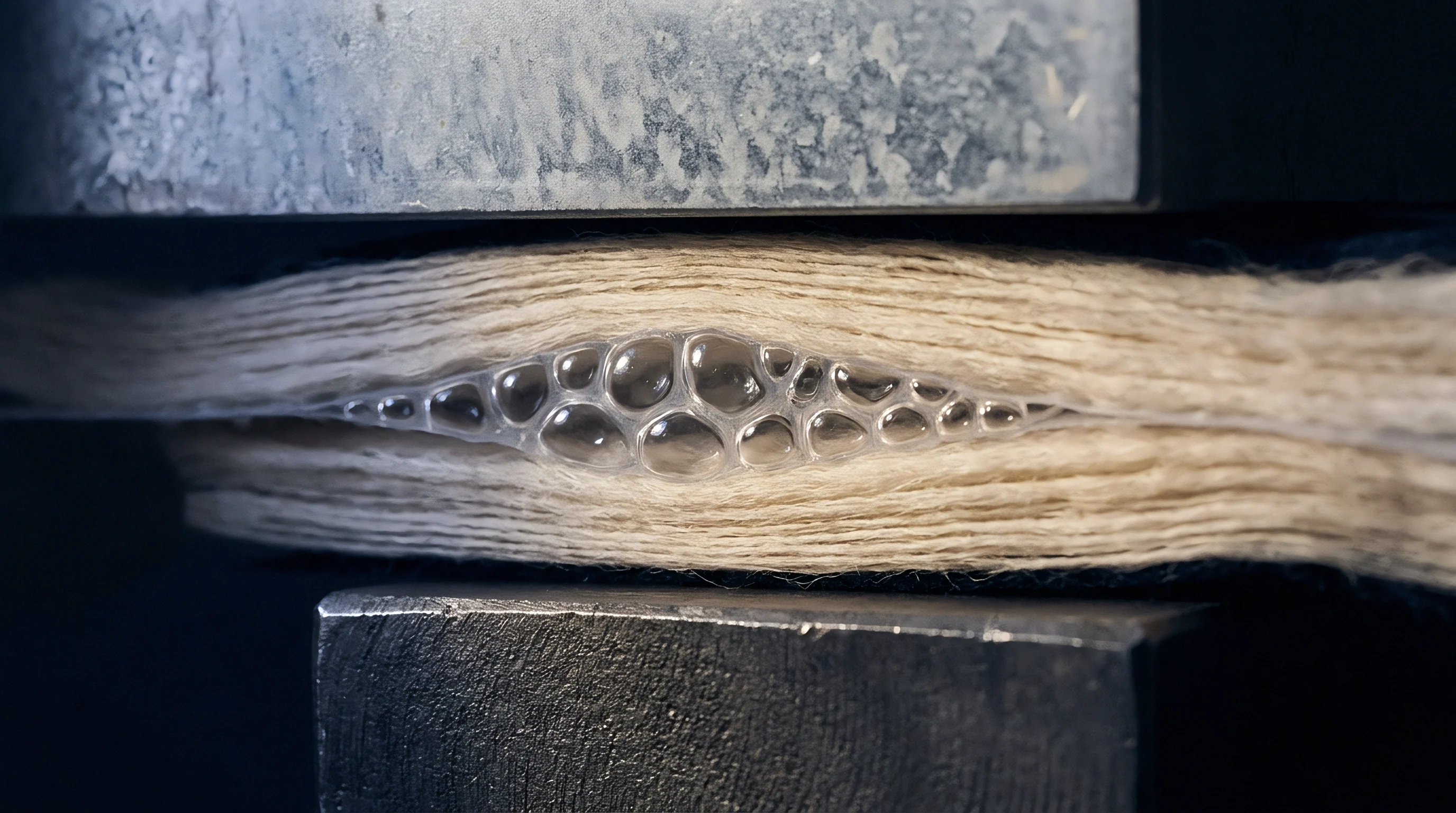
How Does Venturi Geometry Impact Delicate Fabric Rope Propulsion?
A narrow venturi gap concentrates liquid acceleration into a fine high-velocity boundary layer surrounding the passing fabric strand. High kinetic force impinging on delicate filament yarns causes localized filamentation, fiber displacement, and visible pilling. Expanding the throat gap widens the liquor ring, distributing hydraulic force over a larger contact surface area while reducing liquid velocity.
Soft-flow configurations utilize wide circular nozzles operating at low static heads to deliver high volumetric fluid immersion rather than aggressive propulsion force.
Circular venturi inserts perform differently than split or oval nozzles. Round orifices apply uniform radial hydrodynamic pressure, making them suitable for balanced circular knits and smooth filament wovens. Oval and rectangular nozzles compress the fabric rope laterally, preventing internal rope twisting while maintaining stable propulsion on flat woven goods.
Matching nozzle orifice geometry to fabric cross-sectional bulk prevents internal crease formation during prolonged dyeing cycles.
| Nozzle Geometry Profile | Gap Size Range (mm) | Operating Pressure Range (bar) | Maximum Fluid Velocity (m/s) | Primary Fabric Construction Target |
|---|---|---|---|---|
| Micro-Gap Circular | 2.0 – 4.0 | 1.8 – 2.5 | 22.0 | Heavy industrial wovens, high-density polyester poplin |
| Standard Round Venturi | 5.0 – 8.0 | 1.0 – 1.6 | 14.0 | Medium weight jersey, interlock, nylon taffeta |
| Soft-Flow Rectangular | 10.0 – 15.0 | 0.3 – 0.7 | 6.5 | Viscose knits, modal jersey, elastomeric microfibers |
| Variable Multi-Stage Gap | 4.0 – 12.0 | 0.5 – 2.0 | 18.0 | Variable weight cotton blends, delicate structured knits |
Nozzle surface finish inside the jet throat represents another vital mechanical boundary. Surface roughness inside the stainless steel venturi tube increases liquid turbulence and abrasion risk against the passing textile strand. Precision ground inserts finished to mirror polishes reduce frictional contact drag, supporting clean fluid mechanics along the boundary layer.
Internal surface imperfections degrade fabric appearance rapidly under continuous high-speed movement.
A wide nozzle gap running high volumetric flow prevents crease marks on structured woven fabrics without damaging surface fibers.
Wide internal throat clearances eliminate structural rope marks on heavy elastomeric fabrics regardless of total pump pressure settings.
Chafing
Surface damage from hydraulic stress manifests through fiber cleavage, surface fibrillating hairiness, and localized abrasion patches along fabric folds. Spun staple yarns composed of low-tenacity fibers suffer severe surface breakdown under high fluid propulsion forces. Micro-abrasion occurs when high-velocity liquid streams strike stationary or lagging fabric strands inside the transport line.
Synthetic filaments experience structural deformation when kinetic shear disrupts outer fiber orientation.
Mechanical interaction between the vessel wall, nozzle exit ring, and fabric rope accentuates hydrodynamic chafing. Insufficient liquid lubrication inside the venturi causes direct contact between dry metal surfaces and delicate wet fibers. Lubricating agents and bath slippery additives cushion the fabric strand, reducing contact friction and dampening liquid impact forces.
Maintaining proper bath lubrication permits higher fluid propulsion velocities without inducing surface fuzzing or yarn distortion.
- Filament Split Rupture occurs when extreme localized kinetic liquid streams separate multi-filament bundles into free individual surface filaments during high-velocity transport.
- Stitch Deformation Pilling emerges in circular knits when high nozzle drag pulls loop heads out of alignment, creating unstable loose loops that tangle during processing.
- Chafing Crease Striations develop along folded fabric edges when high hydraulic impact forces press dry textile folds forcefully against internal metal pipe walls.
- Elastomeric Core Shearing takes place when high differential pressure stretches covered polyurethane cores beyond recovery limits, causing elastomeric rupture inside the knit structure.
Fiber sensitivity correlates with swell response under wet processing thermal conditions. Cellulosic fibers expand upon moisture absorption, increasing overall strand cross-sectional volume and wet frictional resistance. Viscose and lyocell exhibit reduced wet tensile strength, rendering them extremely vulnerable to hydraulic surface damage at elevated temperatures.
Synthetic polymers like polyester maintain dry-state tensile properties when wet, allowing higher working nozzle pressure limits during rapid shade processing cycles.
Fabric rope speeds matching fluid propulsion velocity prevent shear damage at the nozzle boundary layer.

Arithmetic
Working pressure limits inside a jet dyeing system emerge from fluid dynamics formulas balancing volumetric flow, fluid density, nozzle gap area, and fabric transport mass. Calculating dynamic hydraulic pressure requires mapping total pump capacity against specific venturi cross-sectional dimensions. Operational limits rely on physical calculations rather than nominal pressure gauge readings taken at the pump outlet manifold.
Consider a practical jet machine processing a 220 grams per square metre polyester-spandex circular knit fabric rope at a total load mass of 250 kilograms. The machine pump delivers a volumetric flow rate of 1200 litres per minute through a circular nozzle ring. The installed nozzle has an internal diameter of 60 millimetres surrounding a fabric transport tube holding a compressed fabric rope diameter of 35 millimetres.
Calculating the effective liquid flow cross-sectional area demands subtracting the fabric strand cross-sectional space from the internal nozzle throat area. The total nozzle inner cross-sectional area equals pi times the square of the internal radius, yielding 2827 square millimetres. The compressed fabric rope occupies an estimated cross-sectional area of 962 square millimetres.
The net open dynamic fluid passage area inside the venturi gap measures exactly 1865 square millimetres, or 0.001865 square metres.
Fluid velocity through the dynamic nozzle throat derives from dividing total volumetric liquid flow by net open fluid cross-sectional area. A volumetric flow rate of 1200 litres per minute converts to 0.02 cubic metres per second. Dividing 0.02 cubic metres per second by 0.001865 square metres calculates a dynamic liquid stream velocity of 10.72 metres per second at the nozzle transport constriction point.
| Volumetric Flow Rate (L/min) | Net Fluid Passage Area (m2) | Fluid Velocity at Venturi (m/s) | Dynamic Pressure at Nozzle (bar) | Propulsion Force on Rope (N) |
|---|---|---|---|---|
| 800 | 0.001865 | 7.15 | 0.256 | 14.3 |
| 1000 | 0.001865 | 8.93 | 0.399 | 22.3 |
| 1200 | 0.001865 | 10.72 | 0.575 | 32.2 |
| 1400 | 0.001865 | 12.51 | 0.782 | 43.8 |
| 1600 | 0.001865 | 14.29 | 1.021 | 57.2 |
Dynamic hydrokinetic pressure exerted by the moving liquor stream calculates via the dynamic head formula equal to half fluid density multiplied by velocity squared. Assuming a wet dye bath fluid density of 980 kilograms per cubic metre at 130 degrees Celsius, dynamic head yields 0.5 times 980 times 10.72 squared, producing 56312 Pascals. Converting Pascals to bar demonstrates a dynamic fluid working pressure of 0.563 bar acting directly within the nozzle propulsion boundary.
Calculating overall hydrodynamic propulsion force acting on the fabric strand involves multiplying dynamic pressure by the effective cross-sectional contact area of the fabric strand. Multiplying 56312 Pascals by 0.000962 square metres yields a continuous kinetic propulsion force of 54.17 Newtons pulling the fabric strand through the transport ring. Increasing total pump output to 1600 litres per minute raises dynamic pressure to 1.021 bar and kinetic force to 98.2 Newtons, exceeding structural shear tolerances for delicate knit loops.
Managing dynamic pressure balances pump energy expenditure against fabric safety operational envelopes. High fluid forces demand elevated electric power output from pump drive inverter motors. Operating at an optimal dynamic pressure range preserves fabric structural integrity while containing electrical energy utilization per kilogram of dyed finished textile goods.
This mathematical framework establishes precise upper working operational thresholds for variable fabric weights and machinery configurations without compromising production cycle times.
Gauging
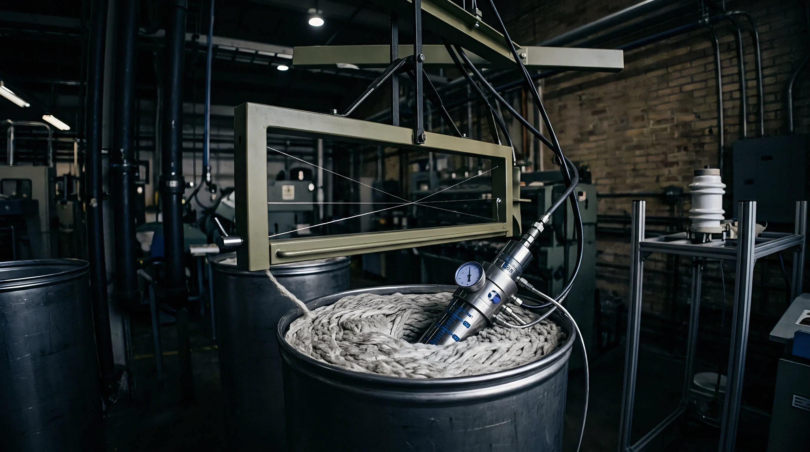
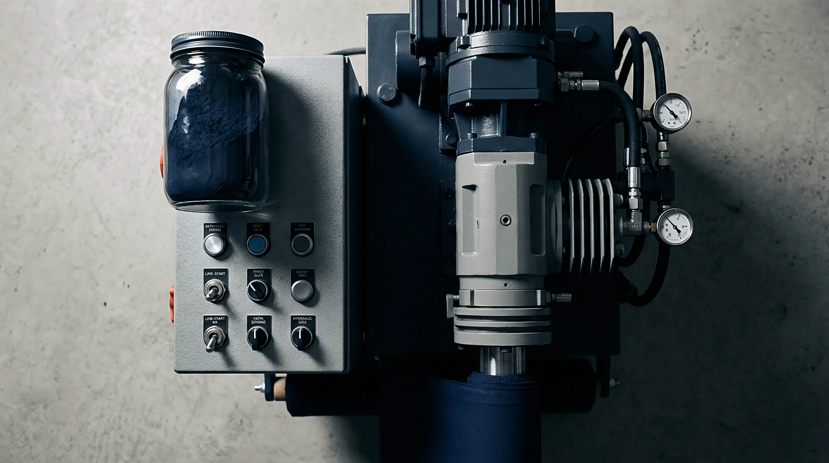
Differential pressure monitoring systems track dynamic hydraulic drop across the nozzle assembly in real time. Installing piezoresistive pressure transducers upstream and downstream of the venturi throat allows continuous measurement of fluid kinetic energy conversion. Sudden pressure spikes indicate physical fabric rope bunching, partial nozzle clogging, or excessive fabric packing density inside the transport tube.
Automated drive controllers linked to pressure transducers modulate pump frequency instantly, preventing catastrophic fabric jamming events.
- Mount high-temperature stainless steel pressure transducers at the pump exit manifold and downstream transport tube entry ports.
- Zero digital transducer signals prior to bath filling to eliminate ambient atmospheric pressure errors from differential calculations.
- Establish low and high differential pressure threshold triggers inside the machine programmable logic controller interface.
- Link transducer dynamic output signals to the main pump frequency inverter drive loop for real-time automatic speed correction.
- Calibrate transducer voltage feedback curves monthly against precision mechanical test gauges under operating temperature conditions.
Reel speed synchronization against dynamic fluid velocity prevents mechanical tension buildup along the moving fabric strand. When the driven transport reel rotates faster than liquid flow propulsion speed, fabric stretch occurs immediately, causing structural distortion and elastomeric damage. Conversely, when liquid velocity exceeds reel surface speed, fabric gathers inside the nozzle throat, causing severe surface chafing and physical abrasion against metal throat surfaces.
Transducer differential signals exceeding 1.8 bar trigger automatic pump frequency reductions to protect fabric loop structure.
Dynamic pressure feedback sensors drift out of calibration under prolonged exposure to aggressive alkaline baths and organic dye carriers at elevated operating temperatures.
Margin
Commercial margins in jet dyeing practices rely on achieving first-time-right shade matching without incurring mechanical fabric damage. Scrapped bulk lots caused by excessive nozzle pressure eliminate profit margins on high-volume production orders. Redyeing abraded fabric batches increases chemical consumption, extends processing time, and doubles total energy expenditure per finished kilogram of cloth.
Operating machines within strict hydrodynamic limits preserves structural fabric value across bulk orders.
Sourcing contracts must state explicit physical fabric quality parameters linked directly to wet processing parameters. Procurement documentation dictates specific testing standard thresholds for pilling resistance, tensile retention, and surface hairiness following wet processing operations. Clear specifications prevent suppliers from running machines at damaging dynamic pressure levels to force rapid production cycles at the expense of fabric longevity.
Standard quality agreements specify that finished bulk fabric must maintain a minimum grade four pilling resistance according to ISO 12945 testing methods while retaining at least eighty-five percent of un-processed greige tensile strength under ISO 13934 protocols, shifting financial liability for surface chafing defects directly onto the finishing mill.