Stitch Density Calibration across Multi Feed Industrial Circular Knitting Machines
Balance positive feeder tape speeds and stitch cam depths to hold yarn run-in within one percent across feeds, eliminating structural barré in finished knits.
Feeder
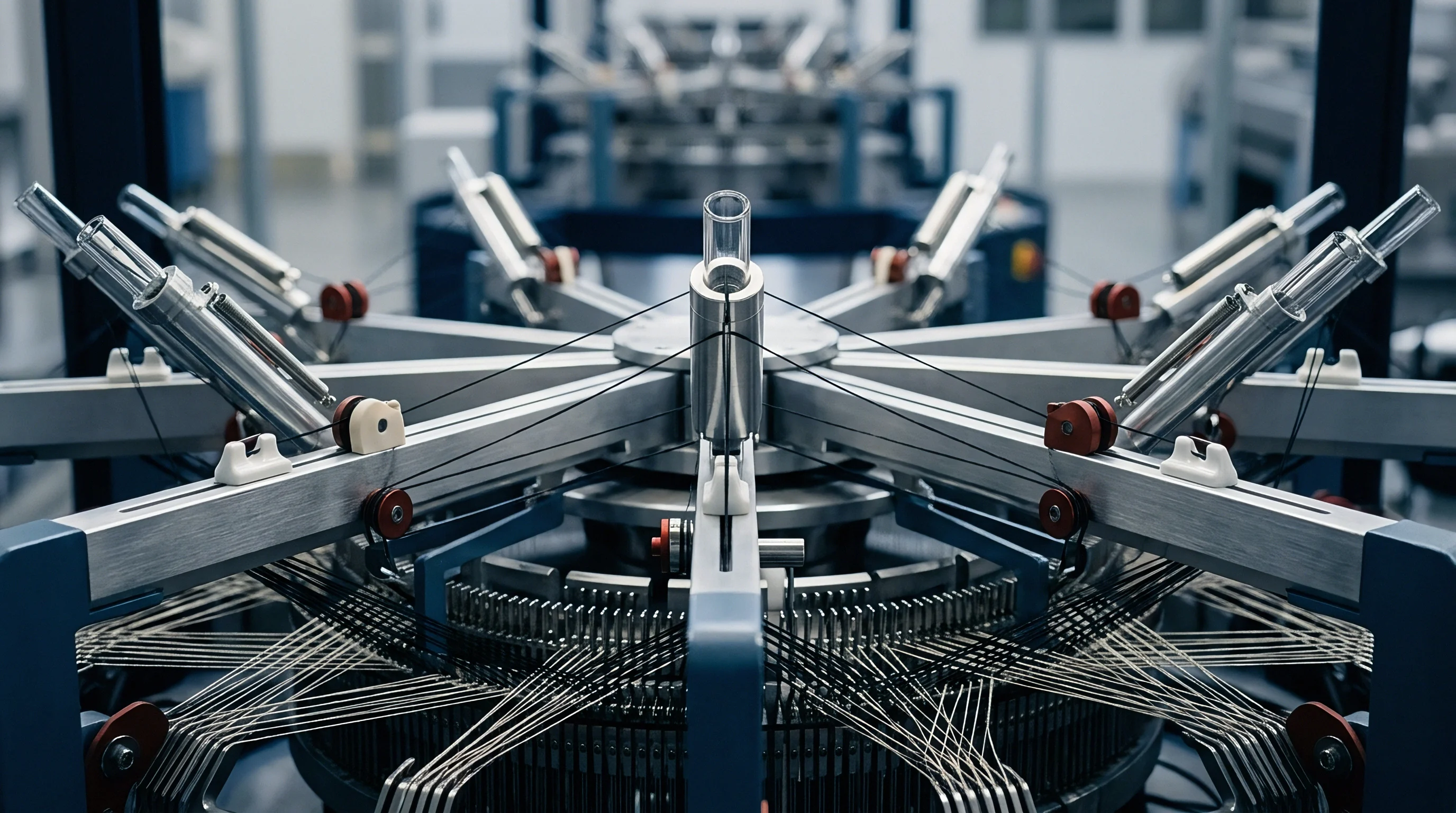
A digital stroboscope aimed at the rotating belt pulleys on a ninety-six station circular jersey frame exposes micro-slippage long before physical yarn breakage occurs. Multi-feed circular knitting machines distribute yarn to needles through continuous mechanical feeds positioned radially around the cylinder perimeter. When thirty-inch diameter frames house seventy-two to one hundred and eight individual feeds, minute discrepancies in yarn delivery across those knitting heads generate cyclic variations in stitch length.
These discrepancies manifest in the greige cloth as horizontal banding, fabric unevenness, and irregular course density. Industrial calibration procedures eliminate these defects by aligning mechanical feed rates across all active stations.
Positive storage feeders govern the primary mechanism of yarn delivery on modern single jersey and interlock equipment. Unlike passive tension discs or demand-based delivery assemblies, positive feeders use drive belts connected directly to the machine drive to pull continuous yarn from overhead creels at a mathematically fixed velocity. The needle consumes exactly the length of yarn advanced by the feeder tape during each revolution of the cylinder.
Balancing this delivery demands precise measurement of the yarn run-in per cylinder revolution across all feeding heads.
A delivery differential of two millimetres per revolution between adjacent feeds creates visible barré bands in finished plain jersey cloth under ambient lighting.
Cylinder rotation creates centrifugal drag.
Storage Tape Velocity and Pulley Synchronization
Positive yarn delivery assemblies lock machine cylinder RPM directly to yarn strand movement through step pulleys or continuous variable transmissions. A master quality pulley mounted on the main drive shaft controls the velocity of the perforated drive belts that loop around each individual storage feeder. If the technician alters the effective pitch diameter of the quality pulley, the linear speed of the drive belt shifts, altering the yarn delivery volume per machine cycle.
The calibration process requires checking that every feeder pulley on the tape circuit features identical diameter steps, clean grooved seating, and zero lint accumulation.
Drive belt tension around the circumference of the machine must remain uniform to avoid localized slip. High-speed multi-feed machines operate with drive belts exceeding eight metres in circumference. Tension variations along this length allow drive belts to float over pulley teeth on feeds furthest from the primary tensioner pulley.
Technicians calibrate this mechanical interface with spring-loaded tensiometers to guarantee equal belt bite on every feeder head around the perimeter ring.
The stitch cam drops two millimetres.
Dynamic Yarn Consumption per Revolution Measurement
A mechanical yarn length meter clamped above an active knitting head records linear yarn displacement in metres per hundred machine revolutions. This measurement, designated as the yarn run-in, serves as the primary verification metric for circular stitch calibration. Greige weight, finished fabric area density, and cross-machine course counts correlate directly with run-in values rather than static cam depth settings.
Technicians run the circular frame at production operating speeds while recording the yarn meters consumed per hundred revolutions across every feed position.
| Quality Pulley Step | Tape Linear Speed (m/min) | Run-In (m / 100 Rev) | Calculated Loop Length (mm) | Greige Fabric Mass (g/m²) |
|---|---|---|---|---|
| Step 1 (Tight) | 192.4 | 687.1 | 2.58 | 162.5 |
| Step 2 (Medium-Tight) | 202.8 | 724.3 | 2.72 | 154.2 |
| Step 3 (Nominal) | 213.2 | 761.4 | 2.86 | 146.0 |
| Step 4 (Medium-Loose) | 223.7 | 798.9 | 3.00 | 139.1 |
| Step 5 (Loose) | 234.1 | 836.1 | 3.14 | 132.8 |
Aligning ninety-six feeds to a target run-in value requires a systematic operational sequence that isolates mechanical feed errors from downstream cam resistance.
- Reference head baseline verification establishes target yarn consumption in metres per hundred cylinder revolutions by running the quality pulley at nominal step three under constant production velocity.
- Circumferential belt tension adjustment equalizes mechanical grip across all storage feeder pulleys using a calibrated spring gauge set to forty-five newtons of perimeter belt pull.
- Individual yarn run-in verification identifies feeding stations deviating by more than one percent from the reference value during continuous rotation.
- Stitch cam fine adjustment aligns the needle draw depth on outlier knitting stations until measured yarn consumption matches the master target run-in figure.
Technicians at the knitting mill routinely maintain that raw yarn count variation from the spinning rotor accounts for all observed course line irregularities.

Tension
Ceramic guides positioned between the overhead creel and the knitting head create cumulative frictional drag that alters how loop lengths form at the knock-over plane. Even when positive storage feeders deliver an identical length of yarn per revolution, differences in running line tension cause the yarn to elongate elastically before entering the needle hook. Cotton yarns stretch up to five percent under elevated drag, while synthetic continuous filaments and textured polyesters exhibit dynamic strain variations exceeding twelve percent.
When this tension relaxes after knitting, loops drawn under higher tension contract, producing tighter stitches and visible fabric bands.
Tension meters demand true zero planes.
Package density inside the side creel forms the first point of variance. Cone-to-cone winding differences produce delivery tensions ranging from two centinewtons to twelve centinewtons at the creel exit eyelet. The positive feeder isolates the needle from creel supply tension provided the yarn wrap on the feeder wheel maintains adequate friction.
Yarn wrap counts on the feeder wheel must remain consistent across all stations. Three wraps on one wheel and four on an adjacent wheel change the yarn delivery release point and generate measurable course striations.
How Drive Tape Slippage Shifts Loop Length?
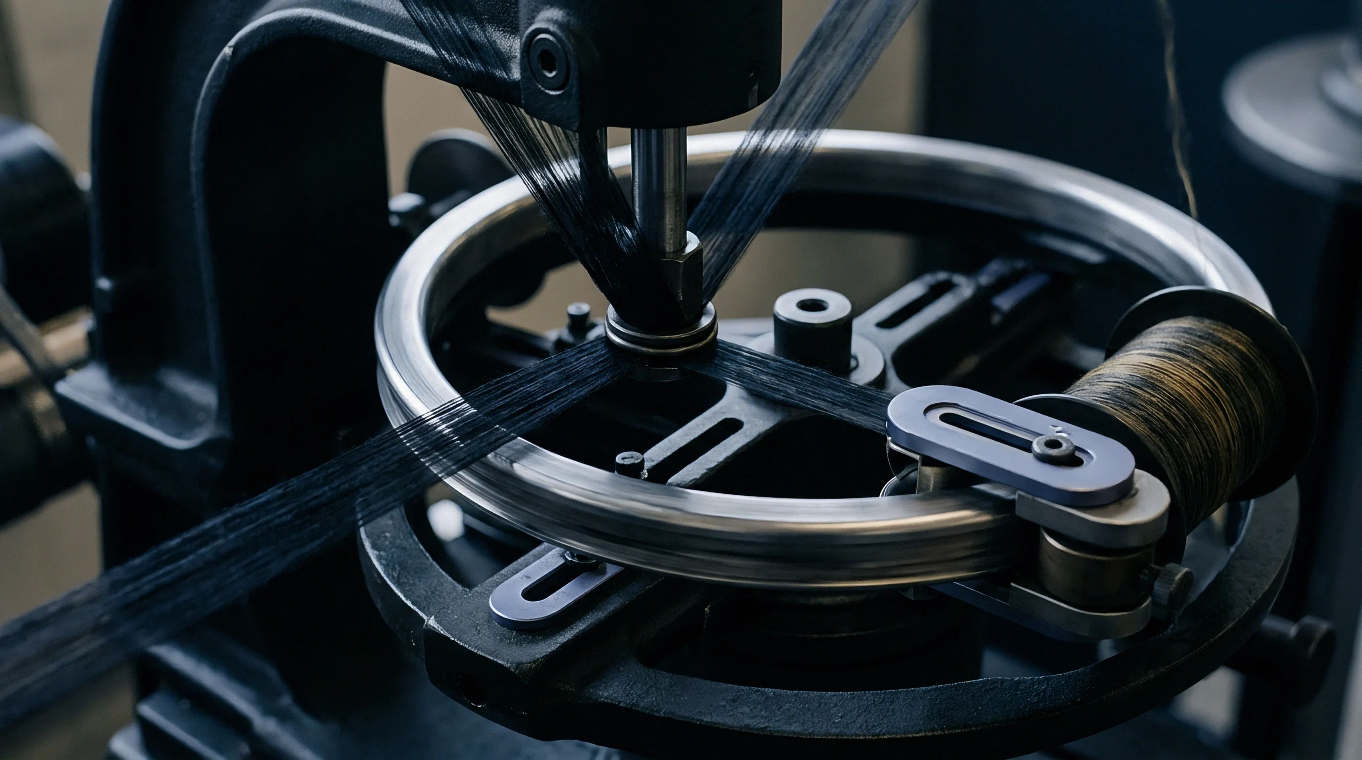
Differential friction across drive belts causes yarn delivery drums to rotate slightly slower than cylinder gearing prescribes. As drive tapes age, oil mists from knitting head mist lubricators degrade the friction coefficient between the synthetic rubber belt and the plastic or aluminum feeder pulleys. Pulleys located immediately adjacent to the lubricator line accumulate oil droplets, inducing up to four percent rotational slip under high load.
Stations subject to drive slip starve the knitting needles of their intended yarn allotment, pulling the loop tighter against the sinker throat.
Off-spec delivery produces horizontal barré bands.
The resulting fabric structural defect reveals itself during garment dyeing. Tighter loops exhibit higher optical packing density, reflecting incident light differently than looser adjacent courses. In reactive-dyed cotton single jersey, a three percent tension-induced loop length decrease creates dark horizontal bars across the tubular body fabric.
When inspected on an illuminated perch, the cloth displays periodic structural lines that mirror the rotational frequency of the knitting cylinder.
Yarn Input Load Measurement at Speed
Handheld electronic tensiometers placed along the running yarn path register instantaneous forces in centinewtons during circular machine operation. The measurement point must sit downstream of the positive feeder wheel and upstream of the yarn feeding eyelet. On a properly calibrated machine running Ne 30/1 ring-spun combed cotton at twenty-eight revolutions per minute, input tension at the knitting eyelet tracks between two and a half and three and a half centinewtons.
Stations recording above four and a half centinewtons indicate damaged ceramic eyelets, lint-clogged stop-motion drops, or excessive sinker cam restriction.
Input tensions exceeding four centinewtons on Ne 30 combed cotton cause premature latch needle hook fracture and excessive loop distortion.
Static drag spikes needle butt fatigue.
Defective yarn packages create uneven drag.
Failure to balance dynamic delivery across all knitting heads results in entire dye lots exhibiting periodic structural banding that forces cut-and-sew facilities to reject garment panels at the inspection table.
Barrel
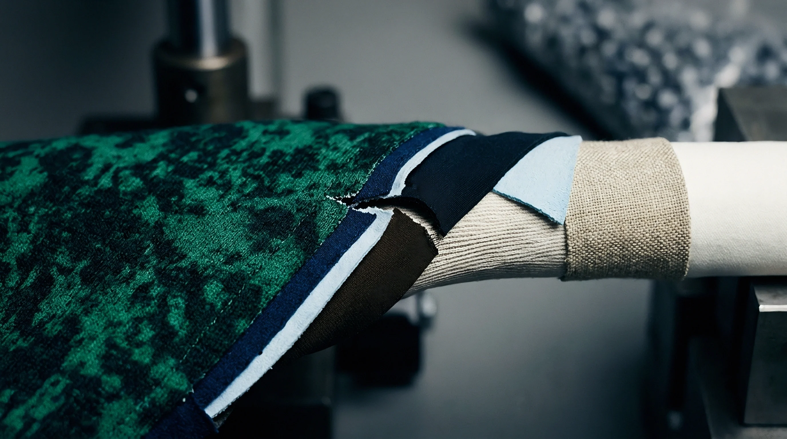
Circular knitting cylinders machined from high-chromium alloy steel host hundreds of precision tricks that house individual needles and sinkers. The mechanical condition of the cylinder barrel directly governs stitch uniformity across the entire circumference. Over months of round-the-clock commercial manufacturing, tricks develop microscopic burrs, lint compaction in trick bottoms, and localized thermal expansion differences.
These physical anomalies alter the sliding resistance of needle stems, disrupting the vertical travel path established by the stitch cams.
Knitting cams undergo gradual metal scouring.
Cylinder concentricity represents another mechanical baseline parameter. A run-out variance exceeding zero point zero two millimetres across a thirty-inch cylinder creates cyclical tension fluctuations as the trick walls oscillate toward and away from the stationary cam boxes. Dial-to-cylinder concentricity on rib and interlock machines proves even more critical, where needle collision risks and gate variations multiply the potential for stitch distortion.
Cam Track Depth and Stitch Draw Balancing
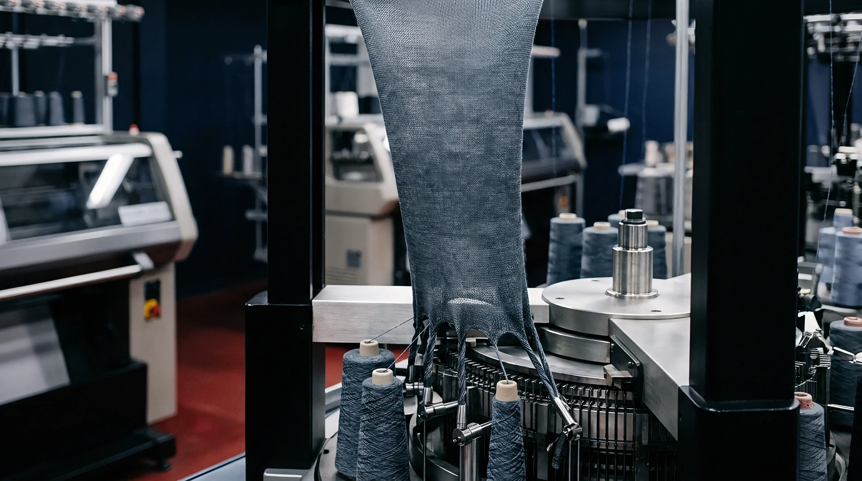
Micrometer adjustments on individual stitch cam blocks determine how far needle heads descend below the knock-over edge. Multi-feed industrial circular knitting machines equip every feed station with an independent stitch cam adjustment screw, calibrated in fractions of a millimetre. Adjusting the stitch cam changes the depth of draw, altering the total amount of yarn drawn into the needle hook during the clearing and cast-off cycle.
Even with positive feeding systems, incorrect stitch cam settings induce yarn robbing between adjacent needles.
Yarn robbing occurs when a descending needle pulls yarn not from the feeding eyelet, but from the previously knitted loop on the adjacent needle that has not yet reached its knock-over position. If cam depth across adjacent feeds varies, the robbing dynamic fluctuates wildy. Feeds with excessively deep cams rob yarn aggressively, generating high local tension spikes that break needle hooks or shear yarn filaments.
Feeds set too shallow fail to draw the allocated run-in length delivered by the positive feeder, causing yarn accumulation, loose loops, and drop stitches.
| Station Cam Setting (mm) | Knitting Tension (cN) | Measured Run-In (m / 100 Rev) | Greige Wales / cm | Greige Courses / cm |
|---|---|---|---|---|
| 1.80 (Under-drawn) | 1.8 | 772.0 | 13.8 | 16.2 |
| 1.95 (Nominal) | 3.1 | 761.4 | 14.0 | 17.5 |
| 2.10 (Over-drawn) | 5.4 | 748.2 | 14.2 | 18.8 |
| 2.25 (Severely Over-drawn) | 8.2 | 731.0 | 14.5 | 20.1 |
Mechanical wear and contamination inside the needle tricks manifest through distinct operational failure modes that disrupt uniform density calibration.
- Lint compaction in trick bottoms limits downward needle descent, causing random tight stitches and needle butt shear during high-speed rotation.
- Scored stitch cam strike surfaces generate irregular needle deceleration curves that induce yarn snatching and micro-chatter across active stations.
- Uneven sinker cam ring wear misaligns the knock-over plane relative to the needle head, distorting the loop cast-off timing around the perimeter.
- Cylinder trick wall deformation increases needle sliding friction, preventing the needle return spring dynamics from fully completing the draw stroke.
Each needle pulls identical yarn length.
Sinker Timing and Knock over Mechanics
Horizontal sinker forward movement pushes the newly formed loop over the throat while the adjacent needle rises to take fresh yarn. Sinker timing can run synchronized with needle descent or operate in an advanced or delayed relationship. In synchronized timing, the sinker belly reaches its maximum inward position precisely as the needle tip descends to its lowest point on the stitch cam.
Synchronized timing minimizes yarn abrasion and tension spikes, making it the industry standard for lightweight single jersey knits.
Advanced sinker timing moves the sinker throat inward before the needle reaches bottom dead center. This setup secures the old loop firmly against the needle stem, preventing loop climbing in loose, open-mesh structures. Delayed timing holds the sinker back until after the needle completes its downward stroke, reducing peak tension when processing weak, low-twist open-end yarns.
Misalignment of the sinker cam ring relative to the needle cam boxes causes adjacent feeds to operate under contradictory timing dynamics, destroying structural density uniformity.
Whether infrared pyrometry on high-speed cylinder assemblies can detect microscopic cam track scouring before mechanical heat expansion shifts stitch draw across adjacent knitting positions remains an open engineering inquiry on production floors.
Draft
Elastomeric yarns introduced into circular single jersey structures alter the entire mechanical equilibrium of loop formation. Bare elastane filaments must never be fed through passive brake tensioners or standard positive storage wheels due to their extreme high-stretch properties. Industrial multi-feed machines process elastane through specialized motorized electronic or friction-wheel elastane feeders that meter the raw filament into the needle hook under precisely controlled elongation.
The ratio of bare elastane delivery speed to cylinder needle speed defines the plating draft ratio.
Greige loop length governs finished density.
Elastane drafts range from two point two to three point eight on commercial swimwear, activewear, and stretch core underwear fabrics. An elastane draft of three point zero means the feeder advances one metre of relaxed filament while the cylinder consumes three metres of knitted path, stretching the elastane three hundred percent at the needle hook. If feeder belts slip or motorized servo units drift by even one percent, the recovery force of the elastomeric core varies radically across knitting stations.
Plating draft variances exceeding two percent between knitting heads induce severe width curl and spiral distortion in finished stretch jersey rolls.

Why Dial Height Variation Causes Stitch Skew?
Vertical spacing between the cylinder trick walls and the overhead disc surface establishes loop shape in interlock and rib machines. On double-jersey frames, dial height directly controls the distance over which yarn travels between the cylinder needles and dial needles during double-knit clearing. Increasing dial height adds yarn to the inter-needle bridge, loosening the overall knit structure and dropping fabric weight per square metre.
Decreasing dial height compresses the structure, elevating knitting tension and steepening course spirality angles.
Circumferential dial run-out produces severe structural distortion. If the dial assembly sits tilted relative to the cylinder by zero point one millimetre, knitting feeds on the low side knit tight, compressed loops while stations on the high side produce loose, open loops. In rotating centrifuge cascades, minute rotor imbalance generates harmonic structural resonance across the drive casing.
Similarly, an out-of-level knitting dial vibrates against its overhead support pillars, transferring periodic mechanical shudder directly into the stitch cam bridges.
The lot fails dimensional audit criteria.
Cam Wear Profiles across Multi Feed Machines
Continuous needle butt impact carves microscopic grooves into hardened alloy steel camming tracks over thousands of running hours. The knock-over edge of the stitch cam absorbs immense repetitive shock loads as needle butts transition from rapid downward acceleration to horizontal travel. Over continuous operational campaigns, these strike surfaces develop wear channels that change the effective descent depth of the needle by zero point zero five to zero point one five millimetres.
Calibrating multi-feed machines necessitates auditing mechanical cam tracks and feeder hardware before locking in production orders.
- Cam profile optical alignment check inspects needle butt contact points under ten-times magnification to detect angular channel erosion and micro-pitting.
- Dial-to-cylinder clearance verification uses feeler gauges at eight radial positions to verify uniform vertical spacing within zero point zero three millimetres.
- Elastane drive wheel tachometer scan measures individual feeding drum RPM to prevent motorized draft drift across active feeds.
- Yarn guide ceramic orifice inspection identifies hairline cracks and wear grooves that snag filament fibrils and induce erratic line tension.
The resulting spirality exceeds seven percent.
A softer yarn package winding density always permits a cleaner draw through intermediate porcelain eyelets.
Shrinkage
Knitted fabric exiting the take-down rollers carries severe mechanical elongation along the longitudinal course axis. Circular knitting machines pull the tube downward under ten to thirty kilograms of take-down tension to clear loops from needle latches. This downward draw stretches the fabric vertically while compressing it horizontally, creating an unstable greige loop geometry.
Stitch density calibration must anticipate the total dimensional relaxation that occurs when the fabric undergoes aqueous scouring, dyeing, and mechanical finishing.
Wet tumbling consolidates relaxed loop shape.
Greige fabric specifications that rely on off-machine course and wale counts mislead production planners. An off-machine single jersey knit might measure fourteen wales per centimetre and twenty-two courses per centimetre at an apparent weight of one hundred and thirty grams per square metre. Following wet processing, washing, and relaxation drying, loop recovery shifts the structure to sixteen wales per centimetre and twenty-eight courses per centimetre, lifting fabric mass to one hundred and sixty grams per square metre.
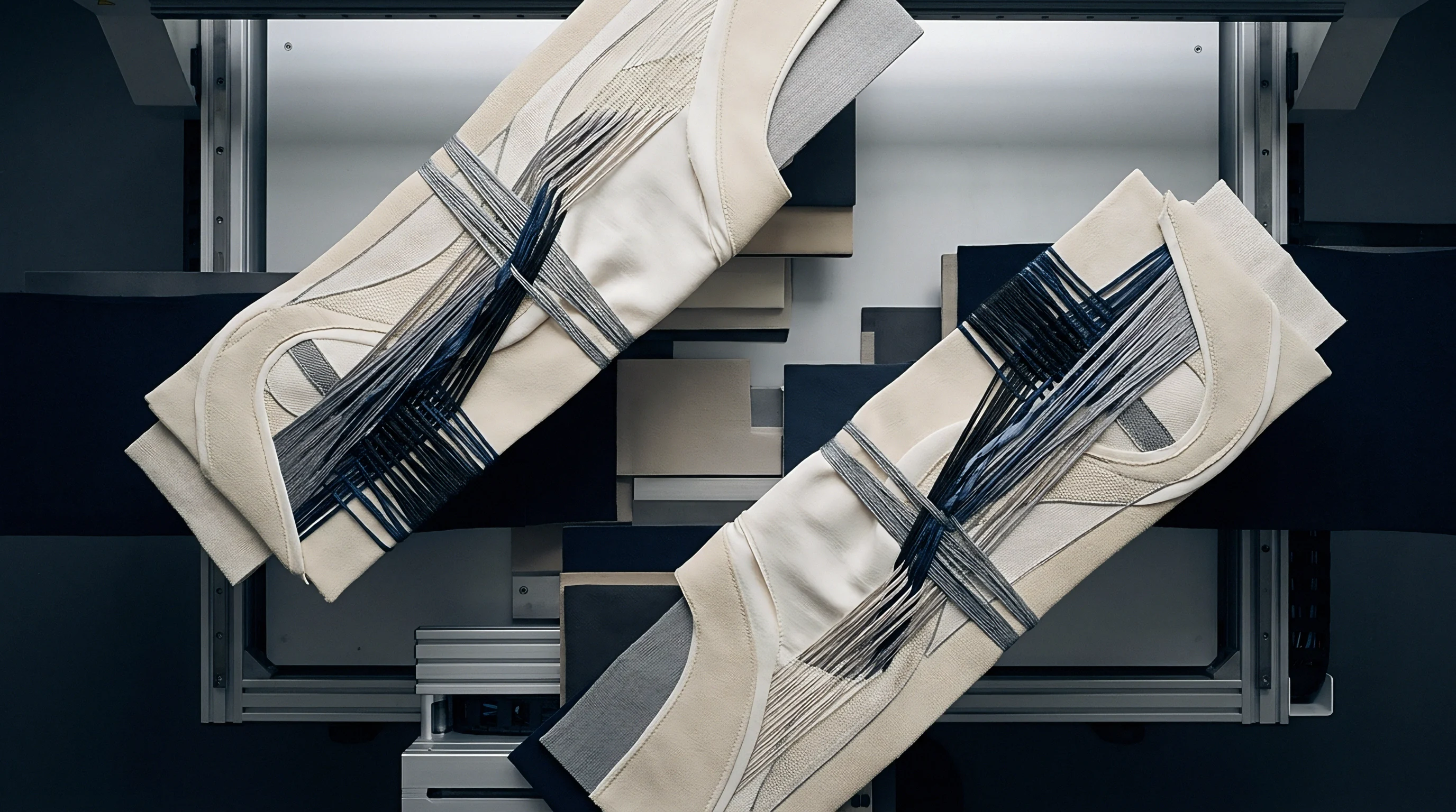
Greige Loop Geometry and Finished State Relations
The classical Starfish and Munden models link yarn loop length in millimetres directly to dry, wet, and wash-relaxed dimensional states. These models prove that finished knit width, stitch density, and dimensional stability depend primarily on loop length and yarn count rather than the immediate mechanical settings on the machine take-down roller. The reference loop length knitted into the greige cloth governs the final mass and density the fabric achieves after all mechanical strain relieves during wet finishing.
| Processing State | Wales / cm | Courses / cm | Stitch Density (Stitches/cm²) | Areal Mass (g/m²) | Width Change (%) |
|---|---|---|---|---|---|
| Off-Machine Greige | 13.5 | 18.0 | 243.0 | 132.0 | Baseline |
| Dry Relaxed (24h Standard Conditioning) | 14.0 | 20.5 | 287.0 | 140.5 | -3.5 |
| Post Dye Jet Scour & Bleach | 15.2 | 23.0 | 349.6 | 158.0 | -11.0 |
| Stenter Slit & Heat Set (Overfeed +15%) | 14.5 | 21.5 | 311.8 | 148.0 | +2.0 |
| Sanforized Compactor Finished | 15.0 | 24.0 | 360.0 | 151.5 | -2.5 |
| Post ISO 6330 4N Wash (5 Cycles) | 15.2 | 24.2 | 367.8 | 153.0 | -3.8 |
| Data measured under standard atmospheric conditioning per ISO 139 at 20°C and 65% relative humidity. | |||||
Course counts climb during mechanical compaction.
Compactor Overfeed and Calender Processing
Industrial felt compactors introduce compressive longitudinal forces to re-orient loop geometry prior to final roll winding. If circular knitting calibration produced erratic loop lengths across adjacent feeds, the compactor cannot rectify the underlying variance. Loose courses compress easily under the heated shoe, while tight courses resist compaction, generating wave-like rippling along the selvedge edges of the open-width fabric roll.
Dyehouse stenters equipped with overfeed mechanisms attempt to balance length and width shrinkage by forcing surplus fabric into the pin chains. Overfeed settings between fifteen and twenty-five percent relax residual lengthwise machine tension. When feeder calibration was neglected at the greige stage, stenter overfeed exaggerates course skew and spirality.
Asymmetrical loops tilt under the compressive air nozzles, fixing garment twist into the finished goods before cutting.
Finished fabric specifications that fail to state the conditioning state per ISO 139 leave the weight figure legally unenforceable against the converter.
Commercial purchase contracts adopting the dimensional tolerances of ISO 6330 shift the financial burden of width loss directly to the knitter whenever relaxation data proves excessive greige stitch length.
Ledger
Capital allocations in circular knitting facilities reflect an ongoing trade-off between machine running speeds and manual calibration labor. Running a multi-feed circular frame at maximum cylinder velocity without routine run-in checks maximizes raw tonnage output while dramatically elevating lot rejection rates. A single ninety-six feed machine producing single jersey at twenty-eight RPM generates over one thousand kilograms of tubular fabric every twenty-four hours.
If that machine knits with a three percent feed-to-feed run-in discrepancy, the entire production volume enters the dyehouse carrying built-in structural barré.
The cost of stripping and redyeing barré-affected fabric exceeds the original knitting conversion fee by a factor of three. If the defect stems from physical loop length differences rather than chemical dye uptake issues, re-dyeing cannot mask the flaw. Garment panels cut from uncalibrated fabric exhibit differential shrinkage across individual body parts, resulting in twisted side seams, uneven hem lengths, and high retail return rates.
Calibration Downtime Economics and Run Intervals
Halting a high-capacity ninety-six feed frame for full yarn length verification incurs direct production capacity losses. A trained technician requires approximately two hours to run a ninety-six feed machine, record individual run-in figures with a yarn length meter, and manually adjust aberrant stitch cams. In commercial operations, technicians perform this calibration protocol upon every yarn lot change, machine gauge conversion, or after five thousand running kilograms per frame.
Scheduled preventive maintenance prevents catastrophic machine component failure. Routine cleaning of positive feeder wheels, verification of drive belt teeth, and micrometer checks of stitch cam blocks protect both yarn and hardware. Mills that run without systematic calibration intervals inevitably face expensive needle breakage cascades when compacted lint or worn cams force needle butts beyond their elastic yield limits.
Audit Tolerances for Industrial Procurement
Fabric technical packs define acceptable stitch density variations between knitting machines executing the same style code. Sourcing agreements must state explicit run-in tolerances and finished density limits to hold commission knitters accountable for structural consistency. Specifying a fabric as simply thirty single combed cotton single jersey at one hundred and fifty grams per square metre allows mills to blend loose knitting on uncalibrated machines with heavy chemical softeners to hit target weight.
Sourcing teams safeguard bulk quality by writing strict verification criteria into supply agreements. Contracts must stipulate that greige yarn run-in across all active feeds remain within a tolerance of plus or minus one percent of the approved master sample. Finished goods must comply with dimensional stability thresholds under ISO 5077 after multiple laundering cycles, bounding residual spirality below four percent on tubular jersey.
Machine downtime schedules, preventative tape replacements, and calibrated runner audits form the technical baseline that protects operating margins on high-speed single jersey production.