Determining Reed Width Requirements from Yarn Takeoff Data
Determining required loom reed width requires converting unraveled weft yarn takeoff data into take-up fractions and adding wet processing shrinkage allowances.


Draft
Calculating target reed width for a fabric specification begins by working backward from the length of a single weft yarn unraveled from a greige or finished sample. Fabric behavior across the loom, past the temple, and through wet finishing depends directly on yarn take-up, for which takeoff measurements establish the baseline. Pulling a weft thread from a measured swatch and straightening it under set tension accounts for the crimp and lateral displacement caused by warp tension and beat-up force.
Establishing this linear value before drawing warp ends through the heddles prevents edge waste and off-gauge rejections.
Standard lab procedures for extracting weft yarns apply precise tensioning so the thread straightens without stretching its fibers. Under ISO 7211-3, a fabric sample ~ usually 250 millimeters or 500 millimeters long ~ is marked and cut. Individual weft picks are pulled out with fine forceps and loaded with a force tied to the yarn’s linear density.
For staple spun yarns, that load is set at 0.5 centinewtons per tex, plus or minus 0.1 centinewton per tex. Continuous filament yarns require enough force to pull out the crimp without hitting the polymer’s yield point. Averaging the extended lengths of twenty picks across the fabric width sets the baseline for reed calculations.
Take-up percentage and crimp percentage are calculated differently, despite frequent confusion between them in production. Weft crimp measures extra yarn length against the width of the woven fabric, whereas take-up expresses that same difference as a fraction of the extended yarn length itself. The distinction changes the output of reed width equations.
For instance, a 160-centimeter cloth sample that unravels to an average yarn length of 176 centimeters has a crimp of 10.0 percent (the 16-centimeter difference divided by 160 centimeters). Its take-up factor, however, is 9.09 percent (16 centimeters divided by 176 centimeters). Substituting crimp directly for take-up in harness calculations under-dimensions the required reed width, forcing operators to over-tension the pick or drop ends per inch to hit Target Greige Dimensions.
- Mount the fabric sample on a flat inspection surface and mark a 500-millimeter horizontal gauge length across the central weft path with a fine-tip marker.
- Extract ten weft yarns from the top of the marked section, discarding any pick with slubs, snarls, or fraying.
- Clamp each isolated yarn in an automated crimp tester under a dead-weight load calculated at 0.5 centinewtons per tex for the nominal yarn number.
- Record extended length across the marked gauge line to the nearest 0.5 millimeter, checking that marks line up with the clamp jaws.
- Calculate the mean extended length across the ten specimens, dropping any measurement that falls more than three standard deviations from the mean.
- Determine the take-up fraction by subtracting the 500-millimeter fabric gauge length from the mean extended yarn length and dividing that figure by the mean extended length.
Applying lab takeoff figures to loom setup requires accounting for the relaxation that occurs immediately after cloth passes the temple cutters and take-up roller. While relaxed sample measurements capture long-term warp tension and finishing contraction, reed sizing must also factor in how weft snaps back during insertion. On modern air-jet and rapier machines, yarn enters the shed under active pneumatic or mechanical tension.
When the reed beats up at the fell and the shed swaps, that tension releases instantly, contracting the yarn laterally before the roll ever reaches storage or wet finishing. Ignoring this quick snap-back causes tight edges, prominent reed marks, and bowing across the middle of the roll.
A take-up calculation applied directly as a crimp percentage underestimates the required loom reed width by an amount proportional to the square of the yarn contraction factor.
Yarn linear density and twist multiplier also affect how lab takeoff data converts to production reed widths. High-twist crepe or voile yarns hold torsional energy that pulls the fabric inward once tension drops. If lab test loads are too light, these yarns micro-snarl, producing artificially short extended lengths.
Low-twist ring-spun yarns do the opposite: they flatten under beat-up force, widening their contact patch at warp crossovers. That added friction binds warp picks and restricts sideways relaxation during desizing. Isolating these mechanical factors through ISO 7211-3 testing is standard before sending a reed draft to the loom floor.
Moving from a sample loom to bulk production, lot-to-lot yarn variations can alter required reed width by two to three centimeters on a 300-centimeter loom. What threshold of twist variance in incoming yarn lots requires adjusting the denting plan before running a five-thousand-meter lot?
Crimp
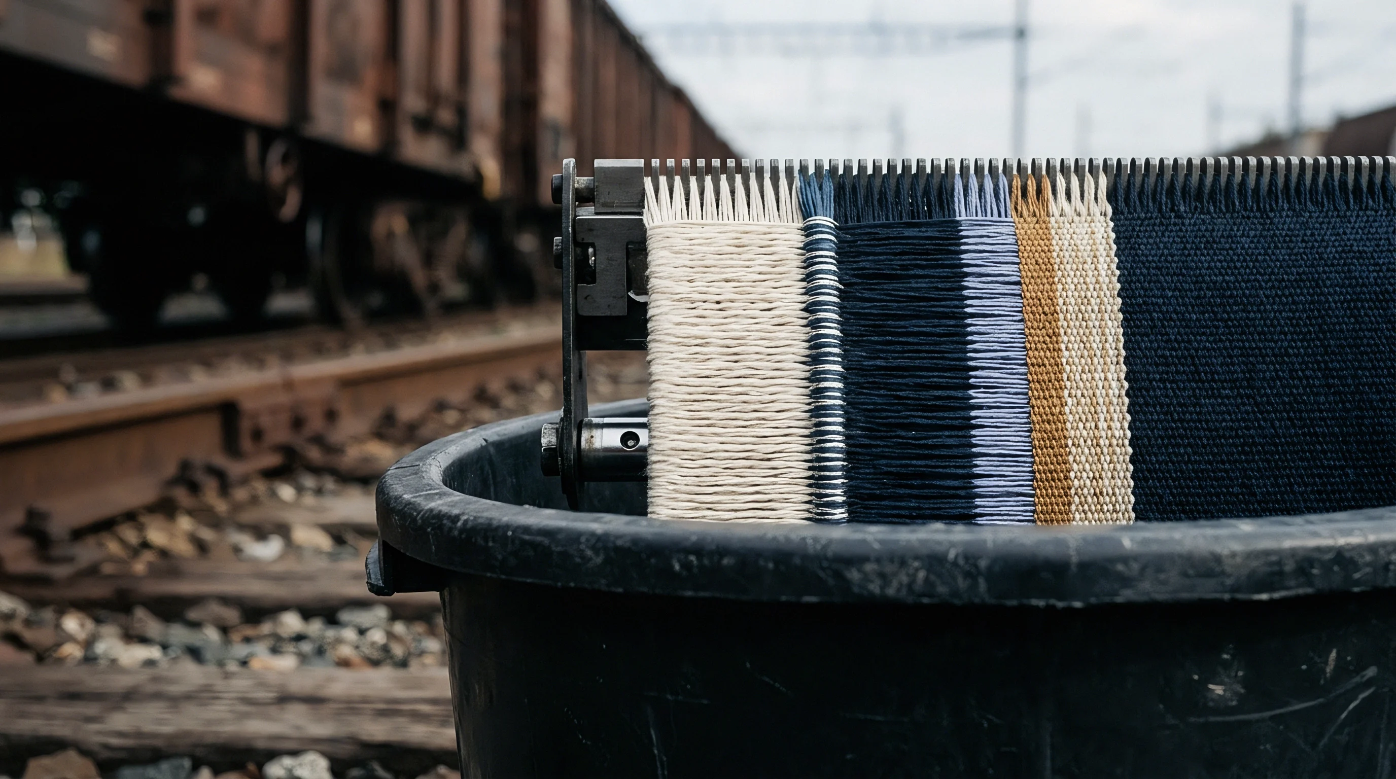
How warp and weft threads interlace dictates how takeoff data translates into width contraction on the loom. Float geometry determines how much bending the weft undergoes. In high-interlacing weaves like plain weave, the pick alternates over and under every warp end, maximizing vertical deflection.
That geometry drives up weft take-up, calling for a wider reed setting than lower-interlacing weaves built from the same yarn count and pick density. Twills, satins, and dobby weaves spread crossovers over longer floats, keeping the weft flatter. Knowing how weave structure alters takeoff lets engineers predict reed widths across pattern changes without setting up new loom trials every time.
Weave Structure Interlacing Intensity and Takeoff Factors
Peirce’s classic geometric model shows that weft undulation depends on warp spacing, yarn diameter, and bending stiffness. In plain weaves, warp cover factor dictates the space left for the weft thread. Higher warp cover forces the weft to bend around rigid, tensioned warp ends, shifting crimp into the weft system.
In dense poplin constructions, raising warp ends per inch increases weft take-up even if pick density doesn’t change at all ~ the weft simply can’t occupy the same plane, so it follows a deeper serpentine path.
The table below shows the relationship between weave architecture, takeoff metrics, and required reed widths for standard 100% combed cotton fabrics. Values assume 35 grams per end warp tension in the shed and a target finished width of 150 centimeters after preparation, dyeing, and stenter finishing.
| Weave Construction | Nominal Warp Count (Ne) | Nominal Weft Count (Ne) | Warp Sett (Ends/cm) | Weft Sett (Picks/cm) | Mean Weft Takeup (%) | Required Reed Width (cm) |
|---|---|---|---|---|---|---|
| 1/1 Plain Weave | 40/1 ring-spun | 40/1 ring-spun | 43.0 | 28.0 | 8.50 | 172.5 |
| 2/1 Ground Twill | 40/1 ring-spun | 40/1 ring-spun | 43.0 | 28.0 | 6.20 | 168.0 |
| 2/2 Right Hand Twill | 40/1 ring-spun | 40/1 ring-spun | 43.0 | 28.0 | 5.80 | 167.2 |
| 3/1 Crowfoot Twill | 40/1 ring-spun | 40/1 ring-spun | 43.0 | 28.0 | 4.90 | 165.5 |
| 5-Harness Warp Satin | 40/1 ring-spun | 40/1 ring-spun | 43.0 | 28.0 | 3.80 | 163.6 |
| 1/1 Heavy Canvas | 10/1 ring-spun | 10/1 ring-spun | 18.0 | 14.0 | 11.20 | 178.0 |
Shifting from plain weave to a 5-harness satin with constant yarn and thread counts drops weft take-up from 8.50 percent down to 3.80 percent ~ a shift of nearly nine centimeters in required reed width. Weaving a 5-harness satin on a reed setup calculated for plain weave leaves greige fabric far over-width. Finishing plants then have to pull excessive lateral tension on the stenter frame to hit target widths, creating internal strain, off-grain bowing, and high residual shrinkage in finished garments.
Can Weft Takeoff Predict Final Greige Width?
Calculating off-loom greige width from unraveled weft length requires factoring in yarn elasticity and the sudden tension drop when cloth leaves the loom. The estimation combines the take-up factor with an elastic recovery coefficient:
W_g = L_u (1 – T_w) (1 – R_e)
Here, W_g is the off-loom greige width in centimeters, L_u is the mean extended unraveled weft length under zero tension, T_w is the take-up fraction from structural crimp, and R_e is the elastic recovery factor upon tension release. For filament polyester, R_e falls between 0.015 and 0.025; for carded cotton yarns, it ranges from 0.005 to 0.012. Leaving elastic recovery out overestimates final greige width.
Take a 3/1 heavy denim targeting an off-loom greige width of 168 centimeters. The build specifies a 7/1 Ne ring-spun warp and a 6/1 Ne open-end weft, woven at 24 ends/cm and 16 picks/cm. Swatch testing yields an average unraveled weft length of 184.2 centimeters over a 160-centimeter sample, giving a weft crimp of 15.12 percent and a take-up fraction T_w of 0.1313.
Determining the necessary reed width W_r for bulk manufacturing requires first establishing the target drawn-in width across the reed wire. The total drawn-in width encompasses the active warp width plus dedicated selvedge allocations on both sides of the machine shed:
W_r = (W_g / ((1 – T_w) (1 – R_e))) + W_s
Assuming a weft elastic recovery factor R_e of 0.008 for the coarse open-end cotton yarn and a total combined selvedge reed width allowance W_s of 4.5 centimeters, the substitution yields:
W_r = (168 / ((1 – 0.1313) (1 – 0.008))) + 4.5
W_r = (168 / (0.8687 0.992)) + 4.5
W_r = (168 / 0.86175) + 4.5
W_r = 194.95 + 4.5 = 199.45 text{ cm}
To hit an off-loom width of 168 centimeters with this denim, the mill needs a minimum reed width of 199.5 centimeters. The warp harness spread must be set nearly 31.5 centimeters wider than the target greige width. Trying to narrow the reed setup to save yarn leads to warp breaks, temple scuffing on the selvedges, and finished weights coming in under specification.
Higher warp cover factors force the weft thread into deeper vertical undulations, systematically expanding the gap between drawn-in reed width and off-loom cloth width.
Shedding geometry also alters how crimp divides between warp and weft. High warp tension flattens the warp line, forcing nearly all crimp into the weft. Closing the shed early ~ before the reed hits front dead center ~ traps the pick under heavy compaction while warp threads cross.
That locks the weft into tighter bends, boosting take-up by up to 1.5 percentage points without changing yarn counts or pick density. Checking loom timing is recommended whenever takeoff figures on production runs drift from prototype tests.
Interlacing frequency dictates weft contraction regardless of machine speed.

Dent
Selecting the reed dent pattern sets how warp ends spread across the drawn-in width. The reed itself is a frame of thin vertical stainless steel blades that form openings called dents. Reed count measures these openings per unit length ~ usually in dents per inch, dents per 2 centimeters, or dents per decimeter.
Pairing calculated reed width with the right reed count and denting order keeps warp density even, prevents reed marks, and leaves room for knots and slubs to pass during weaving.
Total dent count across the harness depends on the drawn-in warp width and ends drawn per dent. Heavy fabrics use fewer ends per dent to minimize yarn rubbing; fine, dense constructions double or triple ends per dent to match required sett without calling for impractically fine reeds. The active dent count N_d is:
N_d = (E_t / E_d)
where E_t is total body warp ends and E_d is ends per dent. The active reed space W_p in centimeters relates to reed count R_c (dents per inch) by:
W_p = (N_d / R_c) 2.54
Choosing a reed from stock means balancing wire thickness against air space percentage. Air space is the open ratio between wires relative to total reed pitch. Dropping below 50 percent air space catches fuzz and micro-slubs, leading to floats and warp breaks.
Going too high with ultra-thin wires allows blades to bend under beat-up pressure, producing uneven pick spacing and vertical streaks.
- Total Body Ends defines the warp thread count needed across the main width, calculated from target finished width and end density, adjusted for finishing shrinkage.
- Denting Pattern sets the sequence of warp ends drawn per dent, ranging from single-end draws in surgical gauze to four- or five-end draws in dense poplins and down-proof fabrics.
- Reed Air Space Ratio measures open space between dent wires relative to total pitch, usually kept between 55 percent and 65 percent for stable air-jet insertion.
- Wire Section Gauge specifies blade depth and thickness based on beat-up force requirements and yarn abrasion.
- Selvedge Dent Reduction increases end density in the outer 10 to 20 dents on each edge to reinforce borders against temple pin pulling and insertion strain.
In air-jet weaving, profile reeds feature a channeled front edge to direct air bursts from main and relay nozzles across the shed. Alignment with the reed cap and sley must be exact. If calculated width pushes edge yarns outside the channel profile, air pressure drops off early, causing loose picks, tip-buckling, and short insertions on the right-hand selvedge.
| Reed Count (Dents/10 cm) | Wire Thickness (mm) | Dent Pitch (mm) | Air Gap Width (mm) | Calculated Air Space (%) | Max Recommended Yarn Size (Tex) |
|---|---|---|---|---|---|
| 60 | 0.45 | 1.667 | 1.217 | 73.0 | 100 tex staple / 300 dtex fil |
| 80 | 0.38 | 1.250 | 0.870 | 69.6 | 50 tex staple / 150 dtex fil |
| 100 | 0.30 | 1.000 | 0.700 | 70.0 | 30 tex staple / 100 dtex fil |
| 120 | 0.25 | 0.833 | 0.583 | 70.0 | 20 tex staple / 75 dtex fil |
| 140 | 0.22 | 0.714 | 0.494 | 69.2 | 15 tex staple / 50 dtex fil |
| 160 | 0.18 | 0.625 | 0.445 | 71.2 | 10 tex staple / 30 dtex fil |
Using the wrong denting pattern can mark plain weaves with visible vertical lines known as reediness. Drawing three ends per dent in a plain weave groups warp threads in pairs or triplets inside the dent, leaving open gaps where the steel wire passed. To fix this in high-density warps, mills use staggered drawing sequences or shift to finer reeds with fewer ends per dent.
Audits of air-jet sheds show that switching from a 3-end draw in a 70 dent/10cm reed to a 2-end draw in a 105 dent/10cm reed removes reediness entirely while keeping total warp ends and drawn-in width unchanged.
Splitting warp end distribution across finer reed dentings eliminates grouping streaks without altering total calculated drawn-in width or target fabric weight.
When calculated width falls between standard commercial reed sizes, mills sometimes try compressing the warp by increasing ends per dent near the outer edges. That uneven density alters weft take-up across the sheet, creating tension spikes, wavy edges, shade variation, and distorted selvedges during calendering.
Under-allocating dents forces operators to crowd wire gaps, generating warp fuzz, end breaks, and repeated loom stops that ruin weaving efficiency.

Contraction
Wet processing contraction is the final major variable needed to translate takeoff data into production reed widths. Fabric straight off the loom doesn’t hold its dimensions through scouring, bleaching, mercerizing, and dyeing. Processing releases stresses trapped in the yarn from spinning, sizing, and loom tension.
At the same time, hydrophilic fibers like cotton, viscose, and flax swell sideways in water ~ expanding in diameter while shrinking in length ~ which pulls warp and weft intersections tighter in both directions.
Scouring strips away sizing agents, fats, and natural waxes from raw greige yarns. As size dissolves in hot liquor, relaxed fibers allow weft threads to wrap more tightly around warp threads, causing immediate width loss. On continuous rope scouring and bleaching lines, longitudinal tension stretches the warp lengthwise, which induces secondary lateral contraction governed by Poisson’s ratio.
Mercerization causes the sharpest lateral shrinkage in cellulosic processing. Exposing cotton greige goods to sodium hydroxide (28 to 30 degrees Baumé) swells fiber cell walls into rounder profiles, forcing yarn to untwist and shorten. Without sufficient lateral grip on a pin or clip frame, width can collapse by up to 12 percent in one pass.
The table below charts cumulative width loss for a 100% cotton printcloth across a continuous preparation and dyeing line.
| Processing Phase | Process Equipment | Applied Lateral Tension | Stage Shrinkage (%) | Cumulative Width (cm) | Effective Weft Takeup (%) |
|---|---|---|---|---|---|
| Loom Reed Setup | Profile Air-Jet Reed | Insertion Pneumatic | Baseline (0.0) | 178.0 | N/A (Drawn Width) |
| Off-Loom Greige | Take-up Winder | Zero (Relaxed State) | -4.5 | 170.0 | 8.50 |
| Enzyme Desizing | Continuous Pad-Batch | Low Longitudinal | -2.9 | 165.0 | 11.20 |
| Caustic Scour & Bleach | Continuous Combi-Steamer | Medium Longitudinal | -2.4 | 161.0 | 13.40 |
| Chain Mercerizing | Pin/Clip Mercerizer Frame | High Transverse Control | +1.2 (Stretched) | 163.0 | 12.30 |
| Continuous Pad-Dye | Thermosol / Pad-Steam | Medium Longitudinal | -3.1 | 158.0 | 15.00 |
| Sanforizing / Compacting | Rubber Belt Shrinkage Unit | Controlled Mechanical | -5.1 | 150.0 | 19.30 |
The sequence shows how cloth drawn across a 178-centimeter reed shrinks to 170 centimeters off-loom, loses more width through wet finishing, and settles at a 150-centimeter finished width. That total loss of 28 centimeters amounts to a 15.73 percent lateral contraction from the reed setup. Finishing plants use overfeed and stenter width adjustments to hold target dimensions, but forcing fabric past its natural crimp balance guarantees high shrinkage when laundered.
Sanforizing applies a final mechanical compaction to secure post-wash stability under ISO 5077. The rubber belt unit compresses the fabric longitudinally, increasing warp crimp. That longitudinal compaction nudges weft picks outward, expanding width slightly if unconstrained.
When exact width control is required, clip expanders in the steam zone set weft spacing right before the belt.
Over-stretching wet processing fabric past its structural crimp balance on the stenter frame produces temporary width compliance that reverts to high shrinkage during home laundering.
When finished lots come in narrow or shrink during laundering, the issue is frequently attributed to raw material variations in fiber swelling or to high weaving tension undermining stenter recovery.
Excessive sizing mill warp tension can prevent the weft from relaxing properly, even when initial reed calculations are correct.
Allowance
Selvedge construction, edge trims, and loom holding devices take up width that must be added directly to body drawn-in calculations. The selvedge acts as a sacrificial border during weaving and finishing, absorbing stress from insertion devices, temple pins, and stenter clips. Omitting exact selvedge allowances from the reed draft results in narrow body widths, edge tears, or shedding failures at the fabric margin.
Shuttleless looms require specific edge treatments that consume reed space. Air-jet and rapier machines use catch cords, leno binding, or tuck-in units to secure cut weft ends. Leno selvedges lock weft tails using paired filament yarns that cross between picks.
Catch cords operate outside the main harness, catching trailing fringe that is cut and pulled into a suction waste bin. This waste fringe eats up 1.5 to 2.5 centimeters of reed width per side.
Tuck-in units avoid fringe waste by using mechanical or air hooks to fold weft tails back into the shed on the next pick. This leaves a neat edge similar to a shuttle loom selvedge, but it doubles pick density over the outer 5 to 10 millimeters. To avoid thick edges that build up during roll winding, the reed draft drops selected warp ends in the tuck-in zone.
- Catch Cord Fringe Allowance sets the length of sacrificial weft tail extending past the edge lock, typically 15 millimeters per side on rapier looms.
- Leno Bind Zone Allocation covers the reed space taken up by leno motion drop-heddles, using two to four dents outside the body warp.
- Temple Burr Retraction Zone reserves space engaged by temple rings, requiring denser selvedge ends to resist pin punctures.
- Stenter Pinning Margin accounts for edge fabric pierced by stenter pin plates in wet processing, taking up to 15 millimeters per border.
- Cutting-Room Trim Boundary covers the outer margin removed by automated cutters to clear pinholes and distorted edge weave before panel assembly.
Temples mounted right behind the cloth fell hold fabric width against inward contraction. Spiked brass rings (burrs) angled outward grip the selvedges to maintain lateral pull. Ring angle, pin density, and ring count depend on fabric weight and contraction force.
Heavy constructions with high take-up require multi-ring temples with sharp steel pins set at a 25-degree angle. Fine filaments call for rubber rollers or fine pin rings to prevent puncture marks.
Adding a two-dent selvedge buffer isolates outer warp ends from extreme deflections where weft exits the main nozzle. Layout plans allocate dedicated space across catch cords, binding zones, body warp, and temple contact points.
Miscalculating selvedge allowances throws off finished width specs. If a build calls for a 150-centimeter usable width and the mill leaves off the 4 centimeters of combined selvedge allowances in the reed draft, net width between pinholes lands at 146 centimeters. Automated cutters then slice through pinholes or clip outer pattern pieces.
Contracts strictly separate usable width from gross edge-to-edge width. Under ISO 22198, usable width excludes selvedges, pinholes, and distorted margins. Commercial terms routinely allow buyers to reject lots or claim debits for lost area if usable width drops more than 1.0 percent below contract.
Delivery terms typically dictate that specified widths refer only to usable cloth between stenter pin lines, making overall edge-to-edge measurements irrelevant in quality disputes.
Margin
Mill economics require balancing fabric width targets against loom capacity. High-speed looms come in standard nominal widths ~ typically 190 to 340 centimeters for apparel and home textiles, and up to 540 centimeters for technical fabrics. Running narrow reed setups on wide machine beds inflates power costs and capital amortization per finished meter.
Loom width efficiency measures active drawn reed width against maximum machine insertion width. Running under 85 percent efficiency raises fixed shed overhead. To improve utilization on narrow goods ~ like 150-centimeter suitings or shirtings ~ mills run multi-width configurations, weaving two or three panels side by side with center cutters and catch cords separating the panels.
Choosing between single and multi-width setups comes down to insertion rates, takeoff dynamics, and center-trim losses. Dual-width weaving doubles output per loom cycle, though extra center selvedges increase yarn waste. The table below compares economics and yarn consumption for a 100% combed cotton 2/1 twill across three loom setups.
| Parameter | Single 190 cm Air-Jet | Dual 340 cm Air-Jet | Triple 540 cm Rapier |
|---|---|---|---|
| Target Finished Width per Panel (cm) | 150.0 | 150.0 | 150.0 |
| Calculated Single Panel Reed Width (cm) | 168.5 | 168.5 | 168.5 |
| Active Panel Count on Loom | 1 Panel | 2 Panels | 3 Panels |
| Total Drawn Reed Space (cm) | 168.5 | 341.0 (with center cut) | 513.5 (with 2 center cuts) |
| Loom Nominal Width (cm) | 190.0 | 340.0 | 540.0 |
| Machine Width Utilization (%) | 88.68 | 100.29 (Over-capacity) | 95.09 |
| Loom Operating Speed (RPM) | 850 | 620 | 380 |
| Weft Insertion Rate (Meters/Min) | 1432 | 2114 | 1951 |
| Selvedge & Trim Yarn Waste (%) | 2.80 | 4.10 | 5.40 |
| Landed Weaving Cost ($/Finished Meter) | 0.48 | 0.36 | 0.41 |
The data shows that running dual panels on a 340-centimeter air-jet produces the lowest landed cost at 0.36 USD per meter, even with 4.10 percent trim waste from the center split. That setup hits a total insertion rate of 2114 meters per minute, maximizing power and floor space efficiency. But fitting two 168.5-centimeter panel setups onto a 340-centimeter bed pushes width utilization to 100.29 percent, exceeding nominal machine width.
That forces mills to trim edge margins or drop speed, leading to frayed edges and insertion faults.
Selvedge trim is unrecoverable waste, but focusing solely on yarn savings can obscure insertion speed gains. Narrow setups on wide air-jet machines also waste compressed air if relay nozzles fire into empty space past the right selvedge. Reprogramming nozzle maps stops air waste, but it won’t fix the loss in loom productivity.
Determining true landed cost means factoring yarn takeoff, sizing add-on, denting labor, power, and finishing yield into one model. Underestimating weft take-up during initial setup creates financial penalties down the line. Fabric arriving at the dyehouse three centimeters narrow leaves two bad options: deliver narrow goods facing contractual debits, or over-stretch on the stenter and risk customer returns from post-wash shrinkage.
Base reed calculations on reliable takeoff data bridges theoretical weave design and practical shed production. Accounting for take-up factors, weave interlacing, wet processing shrinkage, and selvedge margins allows engineers to write denting plans that protect cloth quality, maximize loom output, and lock in target margins.