Predictive Mathematical Modeling of Loop Length in Plain Knits
Predictive loop length modeling establishes exact single jersey finished weight and dimensions by linking yarn count to Munden relaxation constants.
Geometry
A plain jersey loop consists of a needle loop, two side limbs, and two half-sinker loops connecting adjacent wales. The physical length of yarn contained within this single repeating unit governs the physical properties of the finished single jersey. When yarn feeds into a circular knitting cylinder, the machine settings dictate initial stitch formation, yet the underlying yarn dimensions dictate the stable boundaries of the relaxed structure.
A technician calculating target yield begins with the geometric configuration of this bent yarn path rather than relying on empirical machine adjustments.
Classical models developed by F. T. Peirce treated the knitted loop as an arrangement of circular arcs and straight tangent lines. The yarn is assumed to possess a circular cross section of uniform diameter d, following a central axis that bends in three dimensions without flattening. In this idealized geometry, the length of yarn l in a single plain knitted loop follows an exact mathematical relationship based on wale spacing p and course spacing c:
l = 2c + w + 1.57d
Here, w represents the wale spacing between needle centers, c represents the course spacing between successive needle descents, and d represents the effective yarn diameter. Yarn compressibility disrupts this pure geometry under commercial mill conditions. Real spun cotton and synthetic filaments flatten at the interlacing contact points, reducing the effective diameter and shifting the path length.
Modified geometric models introduce a flattening coefficient to correct for transverse yarn deformation, preserving mathematical consistency between theoretical yarn volume and finished areal density.
Under conditioned laboratory atmosphere at twenty degrees Celsius and sixty-five percent relative humidity, single jersey loop length determines finished areal mass within a three percent margin across varying yarn tensions.
D. L. Munden advanced loop analysis by demonstrating that the dimensions of fully relaxed plain knitted cloths depend directly on loop length, largely independent of yarn tension during knitting. Munden derived three fundamental dimensionless constants relating loop length l to course density C, wale density W, and total stitch density S:
C = Kc / l
W = Kw / l
S = C × W = Ks / l2
The constants Kc, Kw, and Ks describe the configuration of the loop in an energy minimum. For a plain knit cotton structure in the dry relaxed state, empirical evaluations establish Kc near 5.0, Kw near 3.8, and Ks near 19.0. When the material undergoes full wet relaxation through tumbling, the constants shift to approximately 5.3 for Kc, 4.1 for Kw, and 21.6 for Ks.
Loop length remains the sole independent structural variable. If the machine technician alters the cam setting to draw a longer stitch, courses and wales per unit length decrease in exact inverse proportion. The shape factor, defined as the ratio of courses to wales, equals Kc divided by Kw, typically holding between 1.25 and 1.30 for stable single jersey.
Loop length fixes the tightness factor of the knit. Tightness factor, defined as the square root of yarn linear density in tex divided by loop length in centimeters, quantifies structural jamming. Standard commercially viable plain knits exhibit tightness factors ranging between 13.0 and 16.0.
Values below 13.0 produce a slack, dimensionally unstable knit prone to severe spirality and edge curling. Tightness factors exceeding 16.0 cause structural jamming during stitch formation, elevating needle hook failure and producing excessive greige hole rates.
Cam
The linear descent of the knitting needle draws yarn across the edge of the sinker belly to create greige stitch length. Circular single jersey frames utilize angular stitch cams to convert rotational cylinder motion into reciprocating vertical needle travel. Stitch cam angle and vertical depth dictate the maximum downward displacement of the needle hook below the knock-over surface of the sinkers.
Mechanical cam depth does not equal the final yarn length incorporated into the loop.
Yarn experiences dynamic frictional resistance as it passes over the edges of closed sinkers and through adjacent needle hooks. The Amontons-Coulomb relationship, modified by the classical Capstan equation, dictates the accumulation of yarn tension across these contact points:
T2 = T1 eμθ
Here, T1 represents incoming yarn feed tension, μ represents the dynamic friction coefficient between yarn and steel, and θ represents the cumulative wrap angle over knitting elements. As the needle pulls yarn to the lowest point of the cam, tension rises rapidly across preceding contact zones. When the leading needle begins its upward ascent while adjacent trailing needles continue their downward draw, a phenomenon known as robbing-back occurs.
The newly drawn loop loses a measurable portion of its yarn to the succeeding needle. Yarn slips back across the sinker edge. Tension drops immediately.
Robbing-back reduces the effective loop length below theoretical cam displacement by ten to twenty-five percent depending on yarn lubricity and machine speed. High yarn friction amplifies tension peaks at the cast-off position, increasing the robbing-back ratio and yielding variable loop lengths between feeds. Needle hooks snap under load.
| Cam Angle | Yarn Friction Coefficient | Input Tension (cN) | Theoretical Draw (mm) | Retained Loop Length (mm) | Robbing Deficit (%) |
|---|---|---|---|---|---|
| 45 Degrees | 0.14 | 2.5 | 3.10 | 2.78 | 10.3 |
| 45 Degrees | 0.22 | 4.0 | 3.10 | 2.62 | 15.5 |
| 50 Degrees | 0.14 | 2.5 | 3.10 | 2.71 | 12.6 |
| 50 Degrees | 0.22 | 4.0 | 3.10 | 2.51 | 19.0 |
| 55 Degrees | 0.28 | 6.5 | 3.10 | 2.33 | 24.8 |
Tension variations across feed stations distort consistency around the circular machine circumference. If mechanical yarn feeding devices slip, individual feeds deliver unequal run-in lengths per revolution, creating horizontal stripiness across the dyed material.
- Cam Profile Inconsistency generates uneven needle acceleration curves, causing cyclic displacement errors between adjacent feeds on older multi-feed cylinders.
- High Yarn-to-Metal Friction elevates cast-off peak tensions, which strips paraffin waxes from combed yarns and plugs needle trick slots.
- Excessive Take-Down Draft stretches newly formed loops past their elastic yield limit, inducing permanent axial deformation before initial batch relaxation.
- Worn Sinker Necks alter the knock-over plane height relative to cylinder needle positions, varying loop lengths along the circumferential axis.
Uncontrolled robbing-back and unbalanced feed tensions produce visible barre defects and unexpected width contractions that cause garment cut panels to fail specified grading tolerances.

Relaxation
Greige rolls leaving the circular knitting machine hold severe mechanical strain imparted by take-down rollers and yarn guides. The loops adopt an elongated, non-equilibrium configuration characterized by flattened course heights and extended wales. Internal stresses stored within the twisted yarn fibers resist this forced geometry.
Until wet processes release these internal moments, greige measurements reflect only transient machine distortions rather than stable physical attributes.
Laundering and dyehouse finishing transfer energy to the fiber structure, initiating fiber swelling and transverse relocation of yarn segments. The loop curves inward, limb angles widen, and sinker loops expand. The total length of yarn inside the loop remains constant while the projected planar area of the unit cell contracts.
Stitch density increases. Dimensional stability in downstream laundering depends entirely on whether finishing processes achieved full structural relaxation.
Contractual rejections occur whenever bulk finished widths vary beyond four percent from values projected using laboratory relaxation constants.
Relaxation stages proceed through three distinct energy levels:
- Dry Relaxation occurs when greige cloth rests without tension on a flat plane for twenty-four to forty-eight hours, discharging superficial line strains.
- Wet Relaxation immerses the substrate in water containing low-foaming nonionic surfactants at sixty degrees Celsius, swelling fibers and collapsing remaining rotational yarn moments.
- Complete Fully Relaxed State subjects the material to repeated wash cycles and mechanical action inside a tumble dryer per ISO 6330 procedures.
Each relaxation phase shifts the structural K-values systematically. For ring spun cotton single jersey, Kc climbs from 5.0 in the dry state to 5.3 in the fully relaxed state, while Kw increases from 3.8 to 4.1. The total loop area constant Ks escalates from 19.0 to 21.7.
If a dyehouse stenter processes greige material under excessive longitudinal overfeed or cross-machine pin tension, the loop shape distorts away from its natural energy minimum. Subsequent domestic laundering by the consumer simply restores the equilibrium K-constants, manifesting as post-purchase shrinkage.
Residual torque within the yarn singles causes loops to tilt relative to the wale axis, generating fabric spirality. The angle of spirality relates mathematically to loop length: longer loops lower the structural jamming limit, providing greater angular freedom for torque dissipation and aggravating wale skew. Off-gauge knitting invites disputes.
What portion of finished width shrinkage originates from fiber swelling versus geometric loop reorientation when processing modified cellulosic fibers through continuous pad-steam operations?
Plating
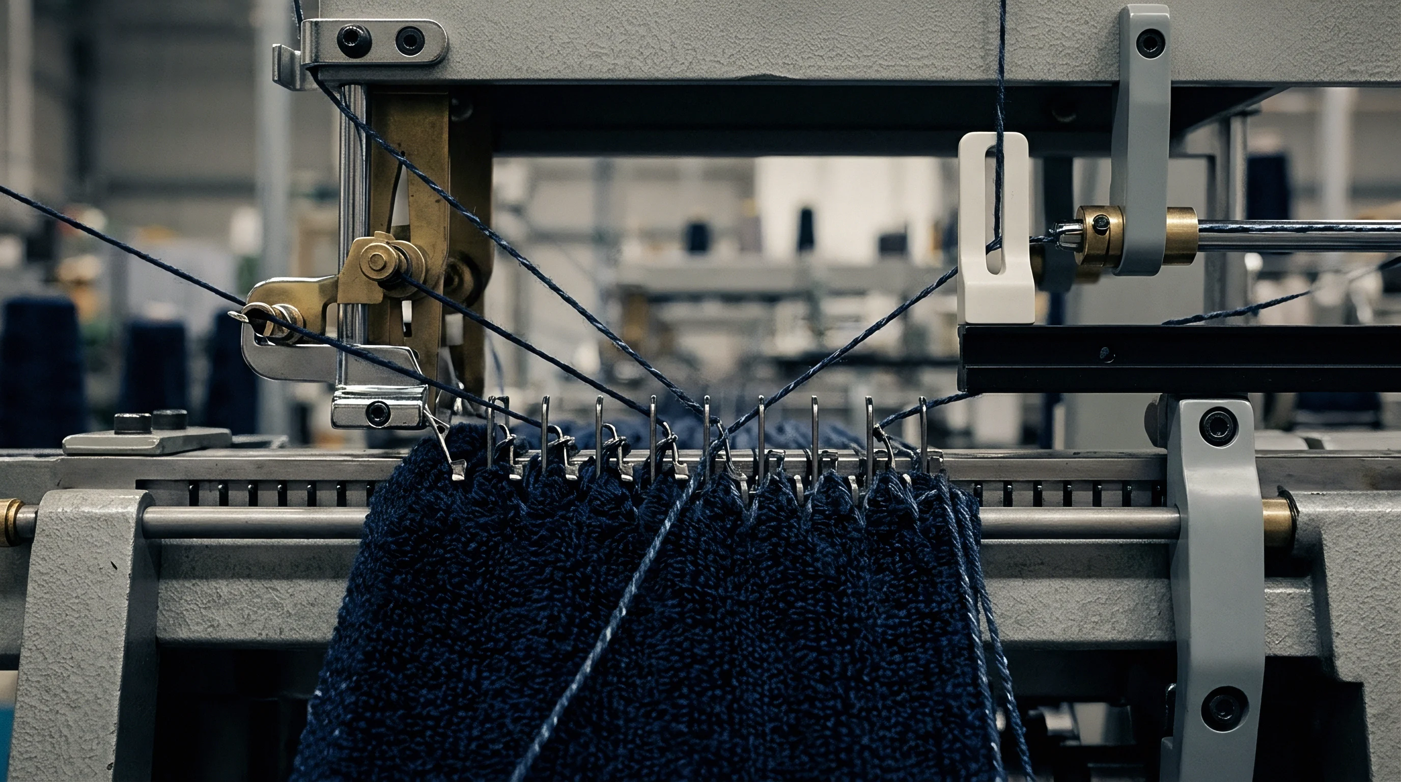
Inserting an elastomeric filament alongside a cellulosic base yarn alters the loop geometry through retractive elastic recovery. Circular machines equipped with dual-feed plating carriers guide bare elastane into the needle hook beneath the primary companion yarn. Both components are drawn simultaneously over the sinker belly, forming a composite knitted loop.
The base yarn occupies the outer face while elastane retreats into the technical back under intense tension.
The operational loop length of the elastane component differs substantially from that of the primary yarn. Positive drive feeding units feed bare elastane under strict pre-draft ratios, stretching the synthetic core filament between two and four times its unextended length prior to knitting. The resulting elastane loop length le relates to the primary yarn loop length lc through the machine draft ratio D:
le = lc / D
Upon clearing the needle and leaving the take-down mechanism, the elastane filament contracts violently toward its unstrained length. This retractive force crushes the primary yarn loop, folding the limbs and closing the sinker spaces. Wale density and course density double compared to unplated single jersey knitted on the identical gauge.
Spandex introduces retractive force. The composite structure departs from classic Munden geometry, requiring modified predictive coefficients.
| Elastane Count (dtex) | Draft Ratio | Cotton Loop Length (mm) | Relaxed Ks Value | Finished GSM (g/m²) | Finished Width (cm) |
|---|---|---|---|---|---|
| 22 | 2.8 | 2.60 | 28.5 | 185 | 172 |
| 33 | 3.0 | 2.60 | 31.2 | 205 | 164 |
| 44 | 3.2 | 2.60 | 34.8 | 230 | 152 |
| 44 | 3.2 | 2.85 | 32.0 | 198 | 168 |
| 78 | 3.5 | 2.60 | 39.5 | 275 | 138 |
Controlling elastane tension across every feed station is paramount. A draft variance of five percent between knitting feeds generates cyclic width banding that appears only after heat-setting on the stenter line.
- Electronic Constant Tension Feeders eliminate spool package diameter run-down effects by maintaining unspooling tension within plus or minus 0.1 centinewtons.
- Thermal Heat-Setting Stenters permanently fix the elastomeric polymer network at temperatures between 185 and 195 degrees Celsius, stabilizing the constricted loop form.
- Plating Carrier Alignment positions the elastane guide hole precisely behind the cotton guide to prevent yarn roll-over and reverse plating defects on the cloth face.
Balanced elastane run-in maintains uniform recovery across the entire cut width.
Formulation
Converting yarn linear density and targeted areal weight into machine run-in settings requires systematic algebraic derivation. Mill technicians often adjust stitch cams through trial cuts on greige rolls, wasting yarn and introducing batch inconsistencies. Rigorous mathematical modeling calculates the exact loop length needed to hit a target finished mass per unit area at specified roll widths before a single cone is loaded onto the creel.
The total mass per unit area M of a fully relaxed single jersey fabric in grams per square meter derives directly from loop length l, yarn count in tex, and the structural constant Ks:
M = (S × l × tex) / 100 = (Ks × tex) / (100 × l)
Here, l is expressed in centimeters, tex represents the conditioned linear density of the yarn, and Ks corresponds to the fully relaxed stitch density constant. Rearranging this equation isolates the required predictive loop length:
l = (Ks × tex) / (100 × M)
Assume an order calls for 100 percent combed cotton single jersey at a target finished mass of 160 grams per square meter. The spinning mill supplies 30s Ne yarn. Converting English cotton count to metric tex yields 19.68 tex via standard conversion (590.5 / 30).
For a fully relaxed, jet-dyed, and tumble-finished single jersey, historical verification sets the empirical constant Ks at 21.6.
l = (21.6 × 19.68) / (100 × 160) = 0.2657 cm = 2.657 mm
Once loop length l is established, total machine run-in per cylinder revolution R follows directly from total needle count N:
R = N × l
For a 30-inch diameter, 28-gauge circular knitting machine, the cylinder contains 2,640 needles. The total required yarn run-in per machine revolution across all active needles at each feed equals:
R = 2640 × 2.657 mm = 7014.5 mm per revolution = 7.015 meters
Positive storage feeders, such as Memminger IRO systems, regulate yarn delivery via precision-ground VDQ drive pulleys. Technicians set the pulley diameter ratio to feed exactly 7.015 meters of yarn into each feed station per cylinder revolution. The math holds steady.
Theoretical values align with finished production outcomes when yarn moisture regain and processing shrinkage are factored into the algebraic model.
Finished yield shifts proportionally with yarn count variations unless the machine run-in rate adjustments compensate at the knitting head.
| Loop Length (mm) | Run-In per Rev (m) | Tightness Factor | Finished Mass (g/m²) | Finished Width (cm) | Wash Shrinkage (%) |
|---|---|---|---|---|---|
| 2.45 | 6.468 | 18.1 | 173.5 | 168 | -2.1 |
| 2.55 | 6.732 | 17.4 | 166.7 | 175 | -3.0 |
| 2.65 | 6.996 | 16.7 | 160.4 | 182 | -4.2 |
| 2.75 | 7.260 | 16.1 | 154.6 | 189 | -5.8 |
| 2.85 | 7.524 | 15.5 | 149.2 | 196 | -7.9 |
Predictive modeling eliminates reliance on converter claims that finished areal weight drift stems exclusively from dyehouse tension rather than incorrect greige loop formation.
Dispute
Commercial conflict over delivered roll weight traces directly back to deviations in physical run-in at the knitting frame. When finished goods fail audit inspections due to deficient areal weight or excessive laundering shrinkage, mills routinely cite dyehouse over-stretching or yarn count variations from the spinner. Quantitative de-knitting analysis arbitrates these disputes by isolating the permanent loop length preserved in the finished goods.
Testing laboratories determine loop length according to standard test procedures such as ISO 7211-3 or ASTM D3883. Analysts unravel courses from conditioned samples under a specified de-knitting tension, calculated to straighten yarn crimp without inducing tensile elongation:
T = 0.5 × tex ± 10%
Technicians remove fifty consecutive loops from across multiple wales, measuring uncurled yarn segments on precision tracking boards under controlled lighting. The average unraveled length divided by the counted loop quantity yields the true operational loop length l. If unraveled loop length measures 2.82 millimeters on goods specified at 2.65 millimeters, the knitter robbed fabric density to increase linear yardage yield per batch.
Converters audit run-in values. Finished yields collapse.
Knitting mills sometimes argue that stenter overfeed settings and chemical compacting resins obscure original loop length measurements, rendering post-dyeing unravelling tests inaccurate. This defense collapses under mechanical scrutiny: while stenter tension distorts course and wale counts per centimeter, it cannot alter the physical quantity of yarn bound within each discrete loop. The total length of yarn per stitch remains invariant across heat settings, dye baths, and mechanical compactors.
Global sourcing agreements protect margin performance by including explicit loop length tolerances rather than relying solely on finished areal weight specifications:
The finished single jersey shall exhibit an average unraveled loop length of 2.65 millimeters within a tolerance of plus or minus 1.5 percent as measured under ISO 7211-3, and deviation beyond this boundary authorizes the buyer to reject the entire batch or invoice the mill for realized garment panel shrinkage losses.