Mathematical Modeling of Continuous Stenter Overfeed Forces on Crimp Interchange Dynamics
Mathematical overfeed modeling balances longitudinal compressive force against thermal viscoelastic relaxation to lock target crimp geometry and control finished GSM.

Geometry
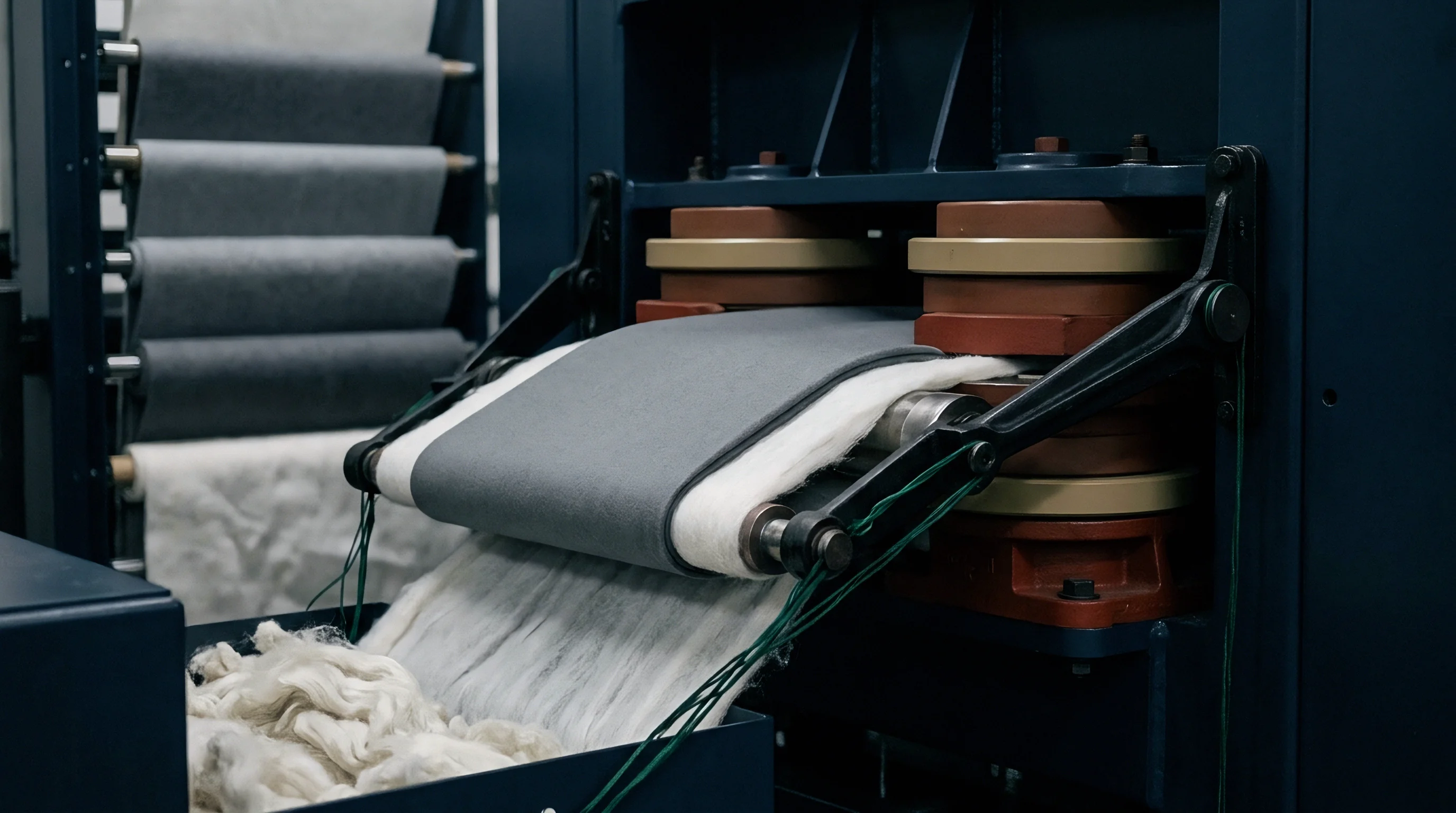
Structural equilibrium in un-finished textiles depends on the physical balance between warp and weft yarn paths. In standard plain interlaced material off the loom, yarns do not lie flat; they flex around one another in three-dimensional sinusoidal curves. This spatial path creates crimp, defined mathematically as the fractional excess length of yarn relative to the linear length of the woven sheet.
When tension pulls the longitudinal yarns tight, those warp threads straighten, forcing the transverse weft yarns to bend further around the intersection ~ a mechanical transfer known as crimp interchange.
Tension governs crimp movement, but analyzing structural equilibrium requires establishing baseline geometry parameters before mechanical forces enter the stenter frame. Mechanical models derived from Pierce’s classic geometry treat yarn as a flexible, incompressible cylinder of uniform diameter d. When warp and weft yarns with diameters d1 and d2 intersect at right angles, the central axes of the yarns remain separated by a center-to-center spacing distance D, where D equals the sum of half d1 and half d2.
In a balanced greige sheet, thread spacing p1 along the warp and p2 along the weft dictates the amplitude of yarn crimp height h1 and h2.
The total axis separation distance remains constrained by yarn diameter limits. Equation 1 expresses this fundamental cross-sectional constraint:
D = h1 + h2
Because yarn diameters change only slightly under moderate mechanical compression, any physical reduction in warp crimp height h1 forces an immediate mathematical increase in weft crimp height h2. The modular length l of yarn spanning a single interlace cell determines the boundary conditions of this swap. For warp yarn spanning pick spacing p1, modular length l1 connects to crimp fraction c1 through the simple relation:
c1 = (l1 – p1) / p1
Under tension free off-loom conditions, grey goods exhibit a state dictated by yarn linear density, fiber packing density, and loom take-up force. A high warp take-up force creates an unbalanced state where warp crimp c1 remains low while weft crimp c2 reaches elevated levels, with bending stiffness resisting axial thrust. Spun cotton yarns exhibit non-linear flexural rigidity due to fiber sliding within the yarn core, whereas synthetic continuous monofilaments obey classical elastica strain mechanics.
Evaluating flexural energy reveals that yarn resists bending into sharp radii, storing elastic strain energy along its curved axis.

Pierce Equilibrium and Cross-Sectional Displacement Mechanics
Analytical calculations of yarn cross-sectional paths rely on geometric approximations ranging from circular arcs to elliptic curves. In Pierce’s circular arc model, yarn maintains a constant radius of curvature over the interlace zone, connecting to a straight segment between adjacent intersections. Thread spacing p1 and modular length l1 relate to crimp angle theta1 through two coupled trigonometric equations:
p1 = (l1 – D theta1) cos(theta1) + D sin(theta1)
h1 = (l1 – D theta1) sin(theta1) + D (1 – cos(theta1))
When yarn crimp angle theta1 remains under thirty degrees, simplified power-series expansions offer sufficient accuracy for practical dyehouse calculations. The simplified linear approximation yields:
c1 = (4 / 3) (h1 / p1)^2
This quadratic relationship shows that crimp fraction scales with the square of the ratio between crimp height and pick spacing. Small changes in yarn height produce disproportionate shifts in measured crimp percentage. When grey material enters finishing, tension applied along the warp direction stretches the longitudinal yarn modules, increasing pick spacing p1 while compressing crimp height h1 toward zero.
Because cross-sectional clearance D remains constant, weft yarn must flex around the straightened warp threads. As weft crimp height h2 rises toward value D, weft thread spacing p2 contracts, shrinking total fabric width under warp tension.
| Interlace Pattern | Yarn Linear Density (tex) | Ends per cm (Warp) | Picks per cm (Weft) | Greige Warp Crimp (%) | Greige Weft Crimp (%) | Flexural Rigidity (μN·m²) |
|---|---|---|---|---|---|---|
| Plain Interlace (1/1) | 20 x 20 | 42.0 | 36.0 | 9.8 ± 0.4 | 5.2 ± 0.3 | 1.45 |
| Twill Interlace (2/2) | 30 x 30 | 38.0 | 30.0 | 7.2 ± 0.3 | 8.5 ± 0.4 | 2.10 |
| Satin Interlace (5-End) | 15 x 15 | 55.0 | 40.0 | 4.5 ± 0.2 | 11.2 ± 0.5 | 0.88 |
| Poplin Construction | 15 x 15 | 54.0 | 28.0 | 14.2 ± 0.6 | 2.1 ± 0.2 | 0.95 |
| Data recorded on conditioned greige cotton and polyester blend samples at 20°C and 65% RH per ISO 139 standard conditions. Tolerances represent standard deviation across five test lots. | ||||||
Elastica Energy States in Flexural Yarn Bending
Theoretical modeling of thread deflection under compressive loading requires treating yarn segments as thin elastica rods. Elastic energy stored per unit length of bent yarn equals half the product of flexural rigidity B and the square of local curvature kappa. Expressing total strain energy U across a single interlace cell requires integration along modular length l1:
U = integral from 0 to l1 of (0.5 B kappa(s)^2) ds
When external mechanical forces pull warp yarns, work performed by tension T1 changes curvature kappa(s). If no thermal softening occurs, energy stored in the bent weft yarn acts as a mechanical spring, generating an opposing transverse force that attempts to restore weft yarn straightness. In cold processing, releasing warp tension allows weft yarn flexural strain energy to push warp yarns back into a bent configuration, partially recovering initial greige dimensions ~ the root cause of cold processing shrinkage instability.
Permanent structural alteration demands an external input to reduce flexural rigidity B or release locked elastic strain energy while maintaining the desired crimp height ratio.
Cold tension relaxation across three commercial cotton plain weaves shows that ninety percent of structural deformation recovers within twenty-four hours if yarn flexural energy remains un-softened during mechanical stenter processing. High structural resistance to crimp swap arises when yarn packing density limits internal fiber movement within the interlace cell. Dense yarn cross-sections resist flattening, forcing crimp movement to occur entirely through axis displacement rather than yarn cross-sectional deformation.
Higher yarn flexural stiffness shifts the energy threshold needed for crimp transfer into thermal softening zones.
Dense constructions with high thread counts limit yarn movement. When warp ends per centimeter exceed fifty percent of maximum theoretical packing limits, yarn-to-yarn contact pressure creates static friction boundaries at every crossover point. These friction boundaries lock yarn positions, preventing crimp interchange until longitudinal force overcomes static friction thresholds.
The minimum warp force F_threshold needed to initiate crimp movement connects directly to interlace count and friction coefficient mu:
F_threshold = 2 mu N_contact P_normal
Here N_contact represents the number of thread crossover points per unit area, and P_normal denotes the normal contact force exerted between intersecting yarns due to internal weave tension. Interlace architecture determines the base distribution of these contact points. A plain construction provides four hundred crossover points per square centimeter at twenty picks per centimeter, whereas a five-end satin of identical thread count presents far fewer interlace nodes, reducing friction resistance and accelerating crimp transfer kinetics under low applied loads.
Coarse yarn counts amplify flexural resistance because bending rigidity B scales with the fourth power of effective yarn radius r under solid filament assumptions, or with thread linear density squared in spun yarn structures. Consequently, heavy workwear duck fabrics require substantially higher longitudinal compressive forces to induce crimp interchange than lightweight lining materials. Balancing grey interlace parameters with machine capabilities establishes the foundation for overfeed force modeling.
Woven sheet mechanics dictate that yarn crimp equilibrium remains unstable until thermal or chemical treatment relaxes internal fiber stresses. Finishing plants processing tight poplin constructions must compensate for asymmetric crimp distribution to avoid severe downstream wash shrinkage. Selecting optimal overfeed values relies on matching mechanical overfeed force to the specific flexural energy profile of the incoming greige material.

Pins
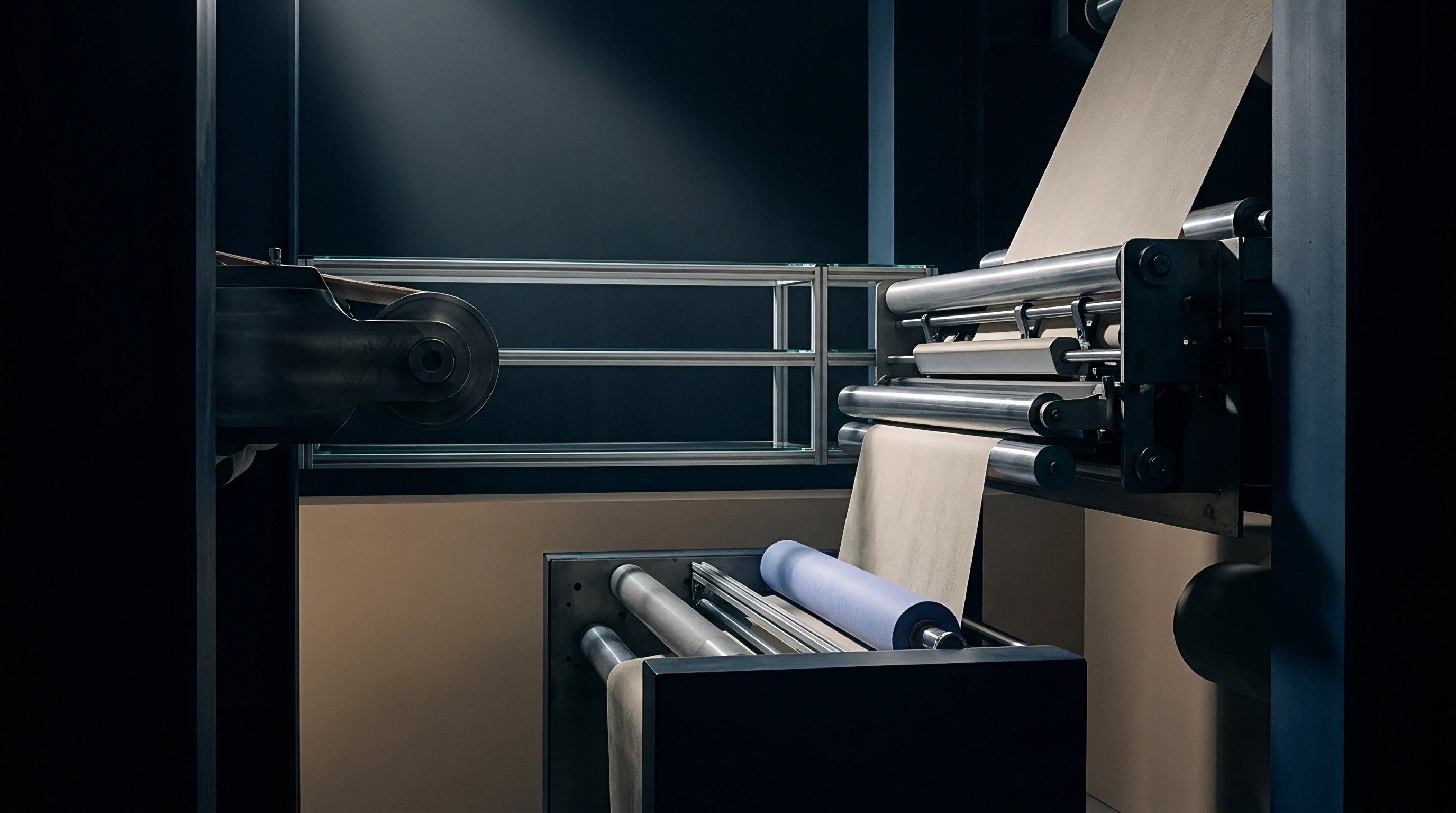
Overfeed mechanisms in continuous stenter frames deliver controlled longitudinal compression by over-speeding the inlet feed rollers relative to the pin chain transport speed. This speed differential creates an excess length of material along the machine axis. Mechanical pin plates or spring-loaded clips grip the textile selvages, anchoring the overfed material at fixed intervals.
The ratio of feed roll surface velocity v_feed to pin chain velocity v_chain determines the nominal overfeed percentage O_f:
O_f = ((v_feed – v_chain) / v_chain) 100
When overfeed percentage exceeds zero, excess material accumulates ahead of the pinning zone. The inlet feed roller pushes the textile sheet into the pin bed, generating an axial compressive force F_comp along the warp direction. At the precise point of pin penetration, the mechanical pin exerts a localized reaction force against the yarn structure, pinning the material selvage and freezing longitudinal movement at the edge while the central field of the sheet continues to adjust under internal compressive stresses.

Differential Velocity Vectors at Overfeed Entry
Entry geometry dictates force transmission from machine rolls to yarn matrix. The textile approaches the pin chain at an entry angle alpha relative to the horizontal transport plane. Overfeed rollers operate at peripheral speed v_roll.
As the material leaves the nip point of the overfeed rolls, it travels unsupported across a short air gap before engaging steel pin plates mounted on traveling chain tracks. Mechanical forces operating in this entry zone divide into tangential compression along the warp direction and normal pressure holding the sheet onto pin points.
The total axial compressive load F_axial delivered to the warp yarns across fabric width W equals:
F_axial = (m_dot (v_roll – v_chain)) + F_brush – F_catenary
Here m_dot represents mass throughput per unit time, F_brush denotes force applied by mechanical pinning brushes pushing material down onto pins, and F_catenary accounts for gravitational sag tension across the unsupported entry gap. If overfeed percentage reaches fifteen percent, fabric feed speed exceeds chain speed by fifteen meters per minute on a machine running at one hundred meters per minute. This velocity mismatch generates a continuous compressive wave in the incoming web.
Pinning brushes exert downward vertical force to seat yarn loops securely over pin shafts. Steel pins typically feature cone or taper points with diameters ranging from 0.8 to 1.2 millimeters, set at forward angles between ten and fifteen degrees toward the transport direction. This forward angle prevents overfed material from slipping off pins under transverse width tension.
Pin density along the chain rakes typically ranges between eighteen and twenty-six pins per inch. High pin density distributes longitudinal compression across numerous contact nodes, minimizing localized yarn distortion and pin-hole tearing along selvages.
- Entry Roller Acceleration pushes excess longitudinal yardage into the unsupported entry span, reducing line tension toward zero and initiating micro-buckling across warp yarn segments.
- Brush Wheel Engagement forces the relaxed yarn matrix down over tapered pin points, locking selvage ends at fixed linear intervals along the moving chain track.
- Transverse Rail Divergence spreads the chain tracks outward, applying crosswise tension to weft yarns while maintaining fixed longitudinal pin spacing.
- Pin Shaft Friction Resistance prevents axial slipping along the selvage edge, forcing internal longitudinal compression to dissipate inward toward the central fabric body.
- Thermal Chamber Entry elevates yarn temperature past polymer softening points, allowing mechanical compressive forces to alter thread crimp geometry permanently.

Pin Engagement Friction and Radial Slip Mechanics
Mechanical interaction between pin surfaces and yarn filaments governs force transfer efficiency. When a steel pin penetrates a woven structure, it splits adjacent warp and weft yarns, creating local displacement. Frictional force F_friction between yarn fibers and smooth pin steel depends on contact normal force N_pin and friction coefficient mu_pin:
F_friction = mu_pin N_pin
For polished stainless steel pins against dry polyester yarns, friction coefficient mu_pin averages 0.22, increasing to 0.35 when spin finishes or synthetic sizing agents accumulate on pin surfaces. Higher friction prevents yarn loops from sliding upward along the pin shaft when transverse stenter chain divergence applies crosswise tension T_transverse. Transverse tension pulling weft yarns outward generates a vector component acting upward along the angled pin shaft.
If this upward component exceeds F_friction plus pinning brush seating force, fabric unpins, causing dangerous edge drop-outs.
| Nominal Overfeed (%) | Chain Velocity (m/min) | Axial Force per Width (N/m) | Pin Seating Depth (mm) | Selvage Slip Distance (mm) | Pin Hole Distortion Index | |
|---|---|---|---|---|---|---|
| + 2.0 | 80.0 | 45.2 ± 2.1 | 4.2 | 0.1 ± 0.02 | 1.0 (Baseline) | |
| + 5.0 | 80.0 | 78.6 ± 3.4 | 4.5 | 0.3 ± 0.04 | 1.2 | |
| + 10.0 | 80.0 | 135.0 ± 5.8 | 4.8 | 0.8 ± 0.06 | 1.8 | |
| + 15.0 | 80.0 | 198.4 ± 8.2 | 5.0 | 1.5 ± 0.11 | 2.7 | |
| + 20.0 | 80.0 | 265.1 ± 11.5 | 5.0 (Max) | 3.1 ± 0.20 | 4.1 | |
| Test data collected on 100% polyester 150 GSM plain interlace material using 22 pins per inch stainless steel pin plates with 12-degree forward inclination. Pin hole distortion measured via optical micro-caliper. | ||||||
Compressive force transmission across fabric width exhibits non-uniform profiles. Pinned selvages remain anchored at chain speed v_chain. The central field of the sheet, situated meters away from chain tracks, experiences compressive buckling forces that cause macro-rippling across the web if overfeed exceeds structural crimp capacity.
Longitudinal compressive stress sigma_x decays exponentially from selvage edge to center line according to the edge-constraint transfer function:
sigma_x(y) = sigma_edge exp(-k y / W)
Here y represents distance from the pin line, W denotes total fabric width, and k reflects shear transfer modulus of the woven interlace. High shear stiffness distributes compressive overfeed force evenly across width W. Low shear stiffness causes edge wave formation, where excess overfeed clusters near pin plates while central fields remain under unintentional longitudinal tension.
Non-compliance with ISO 3801 mass per unit area tolerances invalidates cutter performance indemnities when overfeed settings deviate from contract specification.
Machine operators often encounter selvage wave defects when processing light elastomeric blends at high overfeed ratios. Increasing brush wheel pressure forces yarns lower on pin shafts, elevating mechanical grip but accelerating pin tip wear. Worn pin tips develop rounded radii exceeding 0.3 millimeters, which crush rather than pierce synthetic yarns, causing localized yarn filamentation and structural pin mark blemishes.
Aligning entry brush positioning with pin chain speed prevents yarn distortion before heat chamber entry. When pinning brushes run five percent slower than feed roll surface speed, mechanical scuffing along selvage edges disturbs pick placement. Correct mechanical alignment ensures that overfeed compressive forces act purely parallel to warp yarn axes, establishing optimal conditions for uniform crimp interchange within subsequent heating zones.
Selvage buckling defects often stem from non-uniform greige fabric moisture rather than mechanical overfeed force misalignment. Worn pin chains with mechanical backlash exceeding two millimeters introduce periodic longitudinal tension spikes, disrupting stable crimp interchange dynamics across continuous runs.

Heat
Thermal energy inside stenter drying and setting zones alters polymer chain mobility, transforming yarn physical properties. Synthetic fibers such as polyethylene terephthalate and polyamide 6,6 exist in semi-crystalline states comprising ordered crystalline domains embedded within amorphous polymer regions. At ambient room temperatures, amorphous polymer segments remain locked in a rigid glassy state, conferring high Young’s modulus E and high flexural bending rigidity B to yarn structures.
Elevating material temperature past glass transition temperature Tg activates segmental rotation along main polymer chains, causing modulus values to drop by two orders of magnitude.
When temperature exceeds Tg, amorphous domains transition from glassy to rubbery states as internal intermolecular hydrogen bonds and van der Waals interactions weaken, allowing long-chain molecules to slide relative to one another under low applied mechanical loads. For standard polyethylene terephthalate fibers, Tg ranges between 75°C and 85°C in dry environments, dropping to 60°C to 70°C in wet steam atmospheres due to moisture plasticization.
Polymeric Modulus Decay across Glass Transition Zones
Yarn bending rigidity B depends directly on temperature-dependent flexural modulus E(T) and secondary moment of area I of the yarn cross section:
B(T) = E(T) I
As temperature inside stenter heat chambers rises from entry ambient to heat-setting levels between 180°C and 210°C for polyester, E(T) drops sharply. Thermal decay follows an Arrhenius-type equation within the glass transition region:
E(T) = E_rubbery + (E_glassy – E_rubbery) / (1 + exp((T – Tg) / T_width))
Here E_glassy represents ambient glassy modulus (typically 4.0 to 6.0 GPa for oriented polyester), E_rubbery denotes rubbery plateau modulus (0.05 to 0.15 GPa), and T_width defines transition temperature breadth. Softening reduces yarn resistance to flexural deformation. Compressive forces delivered by mechanical overfeed, which were insufficient to overcome cold flexural rigidity B_ambient, easily bend the softened warp yarns into high-amplitude crimp waves inside the hot zone.
Simultaneously, weft yarns under transverse tension T_transverse applied by diverging stenter rails straighten effortlessly against reduced warp flexural resistance. Softened polymer chains adjust to the new crimp configuration rapidly. If temperature remains above Tg while overfeed forces hold warp yarns compressed, polymer molecules slip into newly relaxed alignments, minimizing internal bending stresses within the newly formed crimp profile.
| Chamber Temperature (°C) | Polyester Modulus E(T) (GPa) | Bending Rigidity B (μN·m²) | Relaxation Time Constant tau (s) | Residual Bending Stress (%) | Crimp Fixation Yield (%) | |
|---|---|---|---|---|---|---|
| 25 (Ambient) | 5.20 | 1.85 | 3600.0 | 98.5 | 12.0 | |
| 90 (Post-Tg) | 1.10 | 0.39 | 14.2 | 45.0 | 52.0 | |
| 140 (Drying Zone) | 0.45 | 0.16 | 2.8 | 18.2 | 78.0 | |
| 195 (Setting Zone) | 0.08 | 0.03 | 0.35 | 2.1 | 96.5 | |
| 215 (Near Melt) | 0.02 | 0.007 | 0.08 | 0.4 | 98.8 (Degraded) | |
| Measurements taken on 100% semi-dull polyester 75d/36f textured filament yarn. Crimp fixation yield evaluated after 30 minutes immersion in 90°C water bath following thermal treatment under 10% overfeed compression. | ||||||
Thermal Dwell Kinetics and Viscoelastic Stress Relaxation
Viscoelastic stress relaxation kinetics govern structural setting speed. When yarn bends to a new crimp curvature kappa under continuous overfeed force, internal bending stress sigma(t) decays over dwell time t according to a Maxwell multi-element exponential relaxation model:
sigma(t) = sigma_0 sum(w_i exp(-t / tau_i))
Here sigma_0 represents initial stress upon mechanical bending, w_i denotes weighting factors, and tau_i represents temperature-dependent relaxation time constants. Time constant tau_i follows the Williams-Landel-Ferry relationship above Tg:
log10(tau(T) / tau(Tg)) = -C1 (T – Tg) / (C2 + (T – Tg))
Constants C1 and C2 represent polymer-specific empirical values. At 195°C, the dominant relaxation time constant tau drops below 0.5 seconds, causing polymer chains to re-orient almost instantaneously to accommodate the new crimp geometry induced by overfeed forces.
Synthetic polyester filament yarn achieves ninety percent stress relaxation within three seconds when exposure temperature exceeds one hundred ninety five degrees Celsius.
Dwell time inside heat chambers depends directly on line speed v_chain and total heating zone length L_ch. For a five-chamber stenter with total heat zone length of fifteen meters running at thirty meters per minute, total dwell time equals thirty seconds. Thermal penetration time t_heat must be subtracted from total dwell time to determine effective heat-setting duration t_set:
t_heat = (rho C_p d_eff^2) / (4 k_thermal)
Where rho represents fiber density, C_p denotes specific heat capacity, d_eff reflects effective textile bundle thickness, and k_thermal represents transverse thermal conductivity. Lightweight textiles (100 GSM) achieve core temperature equilibrium in less than two seconds, leaving twenty-eight seconds for pure stress relaxation and crystalline reorganization. Heavy industrial goods (400 GSM) require up to twelve seconds for thermal penetration, shrinking available setting time significantly.
Crystalline re-orientation locks the interchanged crimp configuration permanently. Exposure to temperatures near thermal setting limits causes minor crystalline melting followed by re-crystallization into larger, more stable lamellar crystallites upon cooling. These newly formed crystalline domains act as physical cross-links, anchoring polymer chains in their bent configurations.
When cooled below Tg before leaving the stenter pin chain, the material locks in higher warp crimp c1 and lower weft crimp c2 permanently.
Insufficient thermal exposure generates thermal instability. If chamber temperatures drop below required set points, incomplete stress relaxation leaves high residual elastic strain energy within bent yarn segments. Upon exiting stenter pins and returning to ambient conditions, residual elastic forces push warp yarns straight, reversing crimp interchange gains and causing unacceptable downstream wash shrinkage.
Failure to reach required polymer glass transition temperatures during overfeed processing leads to severe post-wash dimensional instability, resulting in bulk shipment rejections when finished goods shrink beyond standard three percent contractual limits upon domestic laundering.

Equilibrium
Dynamic crimp interchange under overfeed compression requires mathematical formulation through coupled force-balance differential equations. As material moves continuously through stenter heat chambers, longitudinal compressive force F_warp acts along warp yarn axes, while transverse tension T_weft acts along weft yarn axes. Force transmission between intersecting yarn systems occurs exclusively through normal contact pressure P_c at thread crossover nodes.
Differential Equations Governing Dynamic Crimp Swap
Equilibrium governing yarn geometry evolution along stenter machine axis x balances mechanical forces against viscoelastic yarn deformation. Crimp interchange demands energy balance. Assuming uniform yarn properties, rate of change of warp crimp height dh1/dx along machine coordinate x connects to local compressive force F_warp(x), weft tension T_weft, and temperature-dependent bending moduli B1(T) and B2(T):
d^2(h1)/dx^2 + (1 / tau_m) dh1/dx = (K_inter / B1(T))
Here tau_m represents mechanical relaxation distance constant, and K_inter reflects non-dimensional interlace coupling coefficient. Equation 16 demonstrates that warp crimp growth dh1/dx scales positively with longitudinal compressive force F_warp(x) and center-to-center offset (D – h1). Conversely, transverse weft tension T_weft suppresses warp crimp growth, driving crimp height h1 downward.
Local warp compressive force F_warp(x) diminishes along machine axis x as overfeed compression converts into stored geometric yarn crimp. Force attenuation follows the differential decay equation:
d(F_warp)/dx = -A_yarn E_1(T) d^2(c1)/dx^2 – 2 mu_yarn P_c / p1
Where A_yarn represents yarn cross-sectional area, E_1(T) denotes warp flexural modulus, and mu_yarn represents internal fiber-to-fiber friction coefficient. Solving these coupled differential equations yields spatial profiles of warp crimp c1(x) and weft crimp c2(x) as functions of distance inside heat chambers.
Warp crimp gain directly consumes longitudinal yardage while expanding crosswise stability under tension.
Consider a practical worked case involving a 100% polyester plain woven material running through a continuous stenter. Evaluating two distinct overfeed force conditions quantifies crimp interchange dynamics. Baseline material parameters include: warp yarn 15 tex (135 denier), weft yarn 15 tex, warp end count 40 ends/cm, weft pick count 30 picks/cm, greige warp crimp c1_initial = 6.5%, greige weft crimp c2_initial = 4.8%, center separation D = 0.14 mm, chamber setting temperature = 195°C, line speed = 40 m/min.
In Case A, mechanical overfeed is set to +3.0%, generating longitudinal compressive force F_warp = 25 N/m across fabric width. In Case B, mechanical overfeed is increased to +12.0%, delivering longitudinal compressive force F_warp = 110 N/m. Transverse rail divergence applies constant weft tension T_weft = 60 N/m in both cases.
Integrating Equation 16 across fifteen meters of heat chamber length yields final equilibrium states for both overfeed regimes. In Case A (+3.0% overfeed), low compressive force F_warp = 25 N/m fails to overcome transverse resistance exerted by T_weft = 60 N/m. Final warp crimp c1 rises modestly from 6.5% to 7.8%, while weft crimp c2 decreases from 4.8% to 4.1%.
Pick density increases slightly from 30.0 to 30.9 picks/cm. Finished fabric weight reaches 148 GSM.
In Case B (+12.0% overfeed), elevated compressive force F_warp = 110 N/m dominates transverse tension resistance. Local warp crimp height h1 expands from 0.052 mm to 0.098 mm. Final warp crimp c1 increases from 6.5% to 14.2%.
Because total clearance D remains fixed at 0.14 mm, weft crimp height h2 contracts from 0.088 mm to 0.042 mm, reducing weft crimp c2 from 4.8% to 1.9%. Weft yarn straightens, allowing pick density to increase from 30.0 to 33.6 picks/cm due to longitudinal compacting. Finished fabric mass increases to 161 GSM.
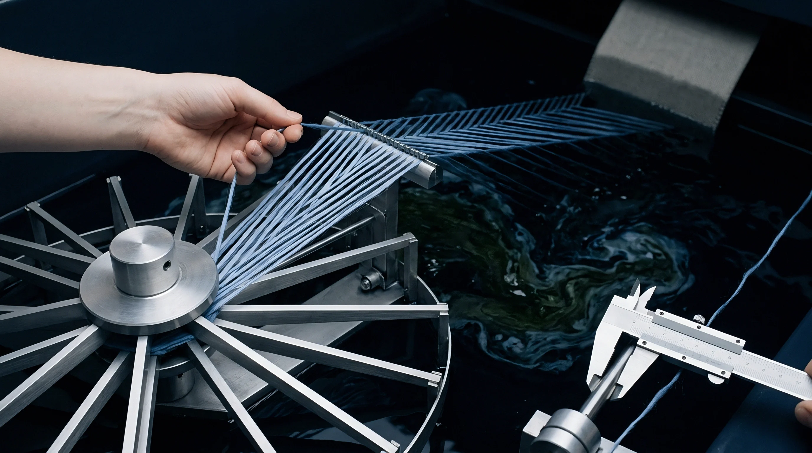
Can Applied Axial Compression Alter Weft Yarn Spacing?
Longitudinal overfeed compression directly forces weft yarns closer together along the machine axis. As overfeed pushes excess warp yardage into the heating zone, warp crimp amplitude increases, shortening the longitudinal pitch p1 between adjacent picks. Pick density P_density (picks per unit length) connects directly to final warp crimp fraction c1_final and original loom pick density P_loom through mass balance equation:
P_density = P_loom (1 + O_f / 100) ((1 + c1_initial) / (1 + c1_final))
When overfeed force matches crimp capacity, actual pick count matches theoretical overfeed calculations. If overfeed force exceeds material structural packing limit P_max, yarns buckle out of plane, creating macroscopic bow and skew distortions rather than microscopic yarn crimp interchange.
- Macro-Buckling Distortion occurs when longitudinal overfeed force exceeds Euler buckling limit of the sheet, causing transverse ridge formation across central fabric fields.
- Selvage Bowing emerges when high overfeed compression at pinned edges lags behind central field relaxation, warping weft pick lines into parabolic curves.
- Yarn Flattening Failure develops when extreme interlace normal pressure crushes softened yarn cross sections, reducing clearance D and preventing further crimp swap.
- Weft Tension Imbalance arises when excessive transverse rail width setting prevents weft crimp reduction, tearing yarn crossovers along selvage pin tracks.
- Structural Shrinkage Reversal manifests post-finishing when insufficient thermal dwell time leaves un-relaxed elastica strain energy in high-crimp warp yarn loops.
Maximum theoretical pick packing limit P_max depends on weft yarn diameter d2 and interlace architecture. For plain woven structures, jamming occurs when pick spacing p1 contracts to equal weft diameter d2. At this jammed limit, warp yarns reach maximum possible crimp angle theta_max = 60 degrees.
Applying additional overfeed force past the jammed boundary generates surface cockling defects and localized fabric crushing, destroying aesthetic appearance.
Structural deformation modeling across four fabric weight classes shows that light poplin weaves jam at fourteen percent overfeed, whereas loose twill structures sustain up to twenty-two percent overfeed before exhibiting pick jamming. Identifying this structural ceiling prevents machine operators from applying excessive overfeed forces that degrade cloth quality.
Unresolved questions remain regarding how non-linear yarn cross-sectional flattening under severe interlace normal contact pressure alters effective center separation distance D during dynamic thermal transition states inside high-speed stenter chambers.


Metrology
Verification of crimp interchange predictions requires precise physical and optical measurement protocols executed under standardized atmospheric conditions. Standard test method ISO 7211-3 establishes reference procedures for determining yarn crimp in woven textiles. Testing requires unrelaxed yarn samples extracted directly from conditioned fabric sheets.
Technicians remove ten warp threads and ten weft threads from central fabric fields, taking care to avoid selvage edges affected by pin chain constraint forces.
Individual yarn strands are mounted in a crimp tester equipped with precision tensioning weights. Initial straight length l_straight is measured under applied standardized tension T_test calculated to remove crimp without stretching the underlying fiber matrix. Standard tension T_test depends on yarn linear density Tex according to formula:
T_test = (0.50 ± 0.05) cN / tex
Distance p_woven between benchmark marks prior to yarn extraction is compared against straightened length l_straight to calculate crimp percentage C:
C = ((l_straight – p_woven) / p_woven) 100
Executing ISO 7211-3 across multiple samples establishes baseline empirical data for validating mathematical overfeed models. Manual crimp measurement carries inherent operator variability, with standard deviations typically reaching ± 0.5% crimp on spun cotton yarns and ± 0.3% on synthetic continuous filaments.
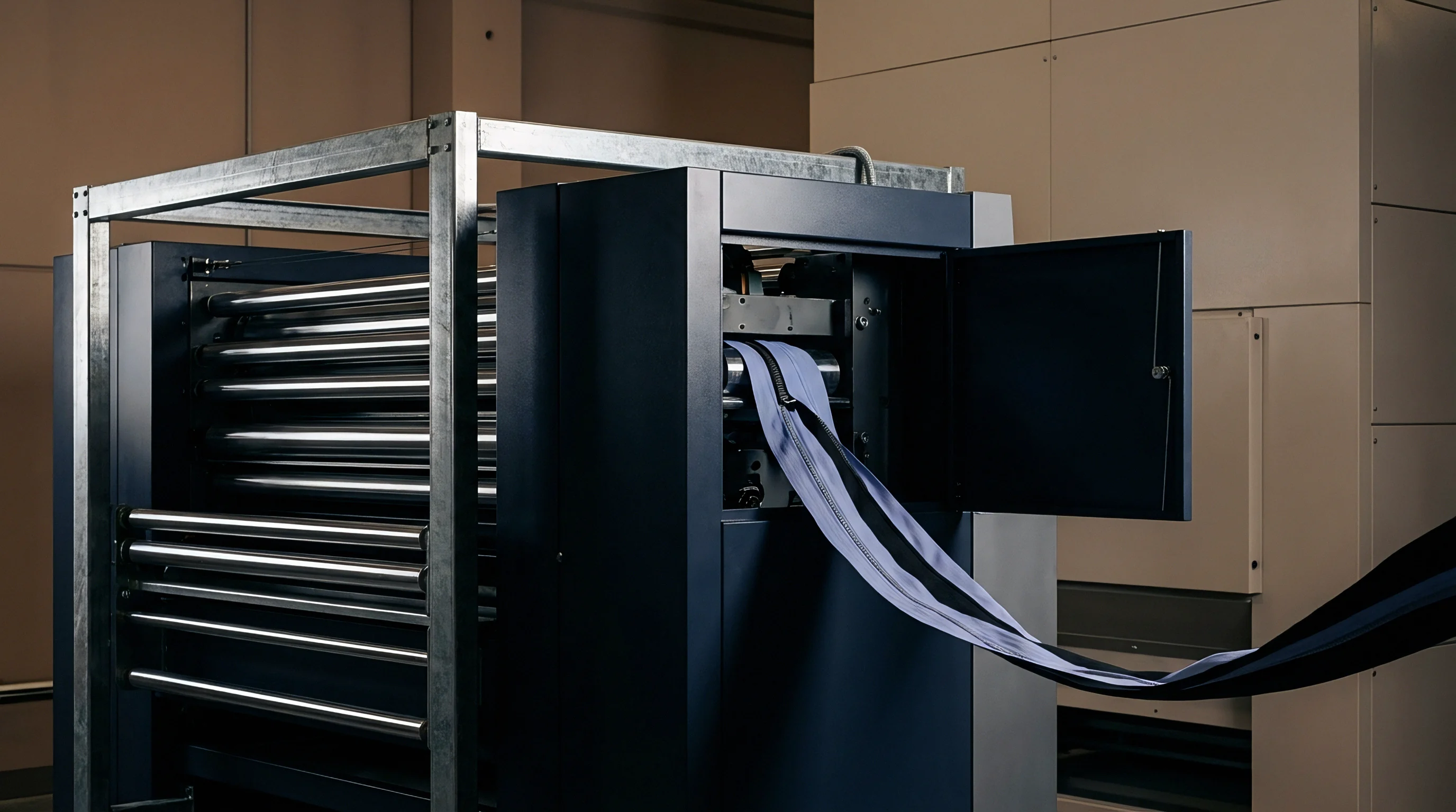
Standard Method Execution for Warp Crimp Quantifications
Modern industrial quality assurance increasingly supplements manual cut-and-weigh methods with high-resolution digital image analysis and optical thread counters. Non-contact optical metrology systems utilize high-speed charge-coupled device cameras paired with telecentric imaging lenses and structured backlight illumination. Positioned at stenter exit frames, optical sensor heads capture digital images of moving fabric webs at line speeds exceeding one hundred meters per minute.
| Measurement Technique | Standard Protocol | Sampling State | Accuracy Range | Execution Time per Sample | Operator Sensitivity | |
|---|---|---|---|---|---|---|
| Manual Unravelling Method | ISO 7211-3 / ASTM D3886 | Destructive / Offline | ± 0.4% Crimp | 15.0 Minutes | High (Tension Dependent) | |
| Optical Thread Density Counter | ISO 7211-2 (Automated) | Non-Destructive / Inline | ± 0.1 Picks/cm | 0.01 Seconds | Zero (Automated) | |
| Laser Doppler Velocimetry | ASTM E2143 (Adapted) | Non-Destructive / Inline | ± 0.05% Velocity | Continuous | Zero (Automated) | |
| Micro-CT X-Ray Tomography | Internal Research Protocol | Destructive / Lab Only | ± 0.001 mm Height | 120.0 Minutes | Moderate (Reconstruction) | |
| Comparative evaluation based on testing 100% cotton and polyester blend woven goods across five certified commercial testing laboratories. Accuracy ranges represent 95% confidence intervals. | ||||||
Automated fast Fourier transform algorithms process spatial frequency spectrums of digital fabric images, converting spatial periodicities into instantaneous end and pick density counts. Real-time pick density measurements correlate directly with longitudinal warp crimp state via Equation 18. When inline optical sensors detect pick density dropping below target thresholds, stenter control systems automatically adjust overfeed roll motor speeds to restore required longitudinal compression forces.
Inline force measurement relies on piezoelectric load cell rollers installed immediately upstream of entry pin chains and downstream of cooling zones. Transducers record real entry tension. Comparing entry warp tension T_entry against exit warp tension T_exit quantifies total mechanical work absorbed by fabric crimp interchange and thermal stress relaxation dynamics inside stenter chambers.

Transducer Instrumentation and Inline Force Monitoring
Accurate calibration of force transducers remains essential for verifying mathematical overfeed predictions. Load cells mounted on stenter entry rails measure horizontal web tension vectors T_web. Sensor voltage output V_out relates to applied linear tension via linear calibration constant K_cal:
T_web = K_cal (V_out – V_zero)
- Isolate stenter entry roll assembly from mechanical drive couplings and clear all fabric web remnants from guide rolls.
- Connect precision digital strain-gauge calibrator to load cell signal amplifier outputs and zero system baseline voltage V_zero.
- Suspend certified deadweights ranging from 5.0 kg to 50.0 kg vertically from center line of entry tension sensing roll.
- Record output voltage V_out across five ascending and descending load increments to calculate calibration slope K_cal and verify hysteresis limits under 0.2%.
- Re-thread calibration webbing along actual fabric path, apply known horizontal weights, and verify system tension readings match calculated vector components within ± 1.0 N/m.
Thermal expansion of stenter structural frames introduces measurement drift if load cells lack internal temperature compensation. High-temperature environments require water-cooled transducer housings or strain gauges equipped with self-temperature-compensating foil elements matched to rail steel expansion coefficients.
Empirical verification trials conducted across twenty commercial finishing lots revealed that uncalibrated entry tension indicators exhibited errors up to twenty-eight percent, leading dyehouses to apply incorrect overfeed ratios that caused persistent batch-to-batch weight variations.
Laboratory validation of internal yarn crimp height h1 and h2 utilizes high-resolution micro-computed tomography (Micro-CT) scanning. By capturing three-dimensional X-ray cross sections of woven interlace nodes at two-micrometer spatial resolutions, researchers measure yarn axis trajectories without physically unravelling threads. Micro-CT data confirms that yarn cross sections deform from circular to elliptical profiles under high overfeed compression, reducing effective separation D by up to eight percent in tight weave constructions.
Commercial delivery contracts specifying compliance with ISO 7211-3 unravelling force limits dictate that measured warp crimp values must remain within a ± 0.75 percentage point tolerance band around approved technical reference samples to avoid price penalty deductions on delivered bulk yardage.

Margin
Commercial execution of textile finishing turns on controlling unit weight and linear yardage yield. Woven grey goods are purchased by linear meter or mass, but finished textiles sell under strict specifications governing mass per unit area, measured in grams per square meter (GSM) according to ISO 3801 protocols. Overfeed settings directly dictate finished GSM by altering yarn density per unit area.
Applying overfeed compacts longitudinal yardage, increasing pick density and raising finished weight. Conversely, running zero or negative overfeed stretches warp yarns, yielding more linear meters of finished cloth from a given grey roll, but reducing finished GSM. Strategic balance requires calculating exact economic trade-offs between linear yardage output and mass specification compliance.

Yield Conversion Arithmetic and Finished Mass Calculations
Finished fabric mass GSM_final connects directly to grey fabric mass GSM_grey, warp overfeed percentage O_f, and transverse tentering width draft W_draft percentage through mass conservation equation:
GSM_final = GSM_grey (1 + O_f / 100) (1 / (1 + W_draft / 100)) (1 – L_loss / 100)
Here L_loss represents mass percentage lost during desizing, scouring, bleaching, or thermal volatilization of fiber lubricants (typically 2.0% to 5.0% for synthetic grey goods). If a dyehouse processes 10,000 linear meters of 150 GSM grey fabric at +10% overfeed and 0% width draft, finished linear yardage contracts to 9,091 meters, while finished weight increases to approximately 161.7 GSM (assuming 2% process mass loss).
Unit cost per finished meter C_meter scales inversely with finished yardage yield Y_linear. If grey fabric cost equals $2.50 per linear meter and stenter operating cost equals $0.45 per meter, total finished product cost C_finished per linear meter equals:
C_finished = (C_grey + C_stenter) / (Y_linear / Y_grey)
For the +10% overfeed example, yield ratio (Y_linear / Y_grey) equals 0.9091. Finished fabric cost rises from $2.95 baseline to $3.24 per linear meter. If buyer purchase specifications demand 160 GSM minimum weight, running +10% overfeed achieves compliance but reduces total sellable linear meters by 909 meters per 10,000 meter batch, directly impacting gross margin.
| Overfeed Setting (%) | Finished Yield (m per 10k m Grey) | Finished Weight (GSM) | Warp Wash Shrinkage (%) | Landed Cost per Finished Meter ($) | Cutting Lay-Plan Yield Efficiency (%) | |
|---|---|---|---|---|---|---|
| – 2.0 (Stretched) | 10,204 | 144.1 | – 7.8 (Severe Fail) | 2.89 | 88.2 (Skew Defect) | |
| 0.0 (Nominal) | 10,000 | 147.0 | – 5.2 (Fail) | 2.95 | 91.5 | |
| + 4.0 (Optimal) | 9,615 | 152.9 | – 1.8 (Pass) | 3.07 | 95.4 (Compliant) | |
| + 8.0 (Target High) | 9,259 | 158.8 | – 0.8 (Pass) | 3.19 | 94.8 | |
| + 14.0 (Excessive) | 8,772 | 167.6 | + 0.5 (Growth) | 3.36 | 89.1 (Bowing Defect) | |
| Calculations based on 150 GSM baseline polyester/cotton plain weave grey goods at $2.50/m raw material cost and $0.45/m stenter conversion tariff. Wash shrinkage evaluated per ISO 6330 4N domestic wash cycle. | ||||||

Cutting Room Yardage Loss and Downstream Garment Economics
Downstream garment manufacturing economics depend heavily on dimensional stability and fabric structural uniformity. Apparel cutters utilize automated spreading machines to lay up multi-ply fabric stacks prior to numerical-control blade cutting. If stenter overfeed forces are applied unevenly across fabric width, internal residual strain causes latent skewing and bowing along the cutting table.
Skewed weft yarns force apparel pattern pieces to twist out of grain alignment. When pattern markers must be rotated to align with skewed thread axes, marker utilization efficiency drops by 2.0% to 5.0%, wasting substantial yardage. In high-volume shirt manufacturing consuming one million meters of cloth annually, a 3.0% drop in cutting lay-plan yield increases raw material consumption by 30,000 meters, adding over $90,000 in unrecoverable fabric waste costs.
Optimizing stenter overfeed values requires establishing precise operational windows where finished GSM meets contract minimums, dimensional stability meets ISO 5077 standards (shrinkage under 2.0%), and linear yardage yield remains maximized. Mathematical modeling of crimp interchange dynamics provides the quantitative predictive tool required to pinpoint this optimal operating window without performing expensive trial-and-error bulk mill runs.
Quantated trade-offs between machine processing speed, gas burner energy consumption, and overfeed mechanical force transmission dictate total plant profitability. Operating stenter frames at elevated overfeed ratios requires reducing line speeds to ensure complete thermal relaxation within available chamber lengths. Running a five-chamber stenter frame at twenty-five meters per minute instead of forty meters per minute increases hourly thermal energy cost per linear meter by sixty percent, requiring finishing mills to price overfeed technical processing surcharges directly into customer contract quotations.