Structural Loop Geometry Modifications in High Gauge Circular Knits
Modifying stitch cam depth and sinker timing in high-gauge circular knits optimizes loop length to stabilize spirality and boost bursting strength.
Sinker
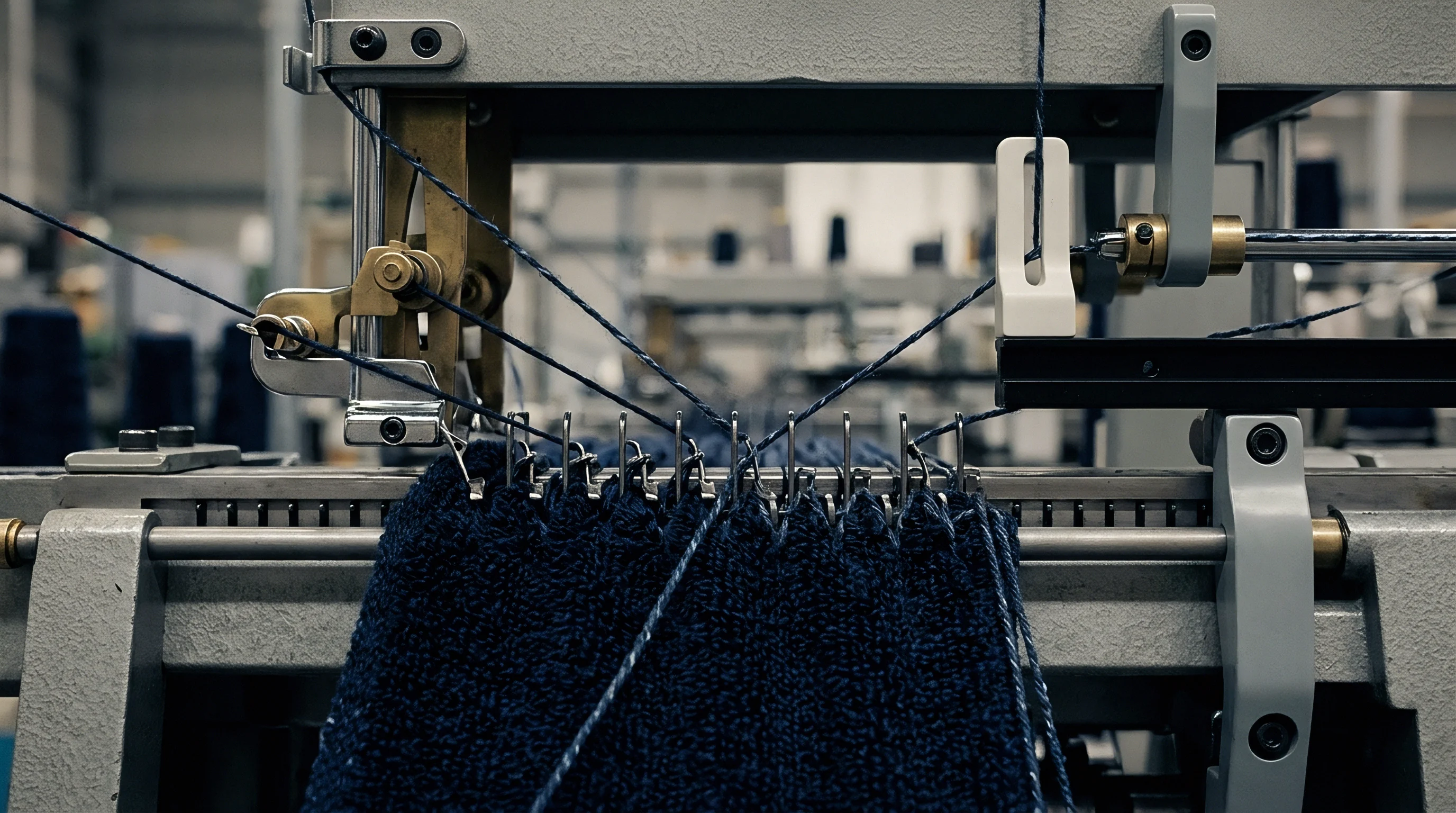
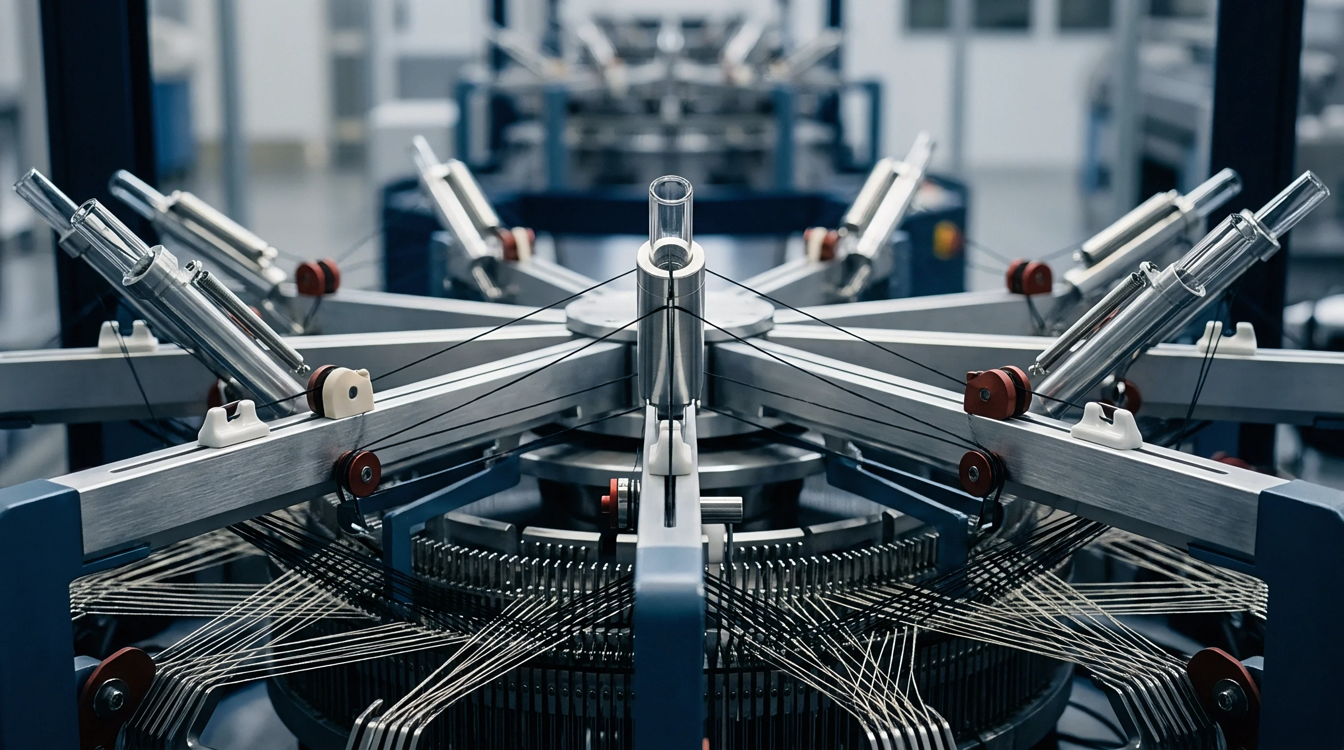
Circular knitting equipment operating above twenty-eight needles per inch demands precise mechanical alignment between the descending needle cylinder and loop-forming elements. As machine cut increases to E32, E36, and E44, the physical space between adjacent needles contracts significantly. At E44 gauge, needle pitch drops to approximately 0.577 millimetres, forcing yarn clearance margins down to fraction-of-a-millimetre tolerances.
Under these dimensional constraints, traditional loop formation dynamics break down if yarn tension spikes during the draw. Controlling structural geometry requires active control over the sinker movement cycle to form uniform loop heads without over-straining fine-denier synthetic or high-count combed cotton yarns.
Needle selection dictates gauge bounds.
Stitch Cam Settings and Holding down Mechanics
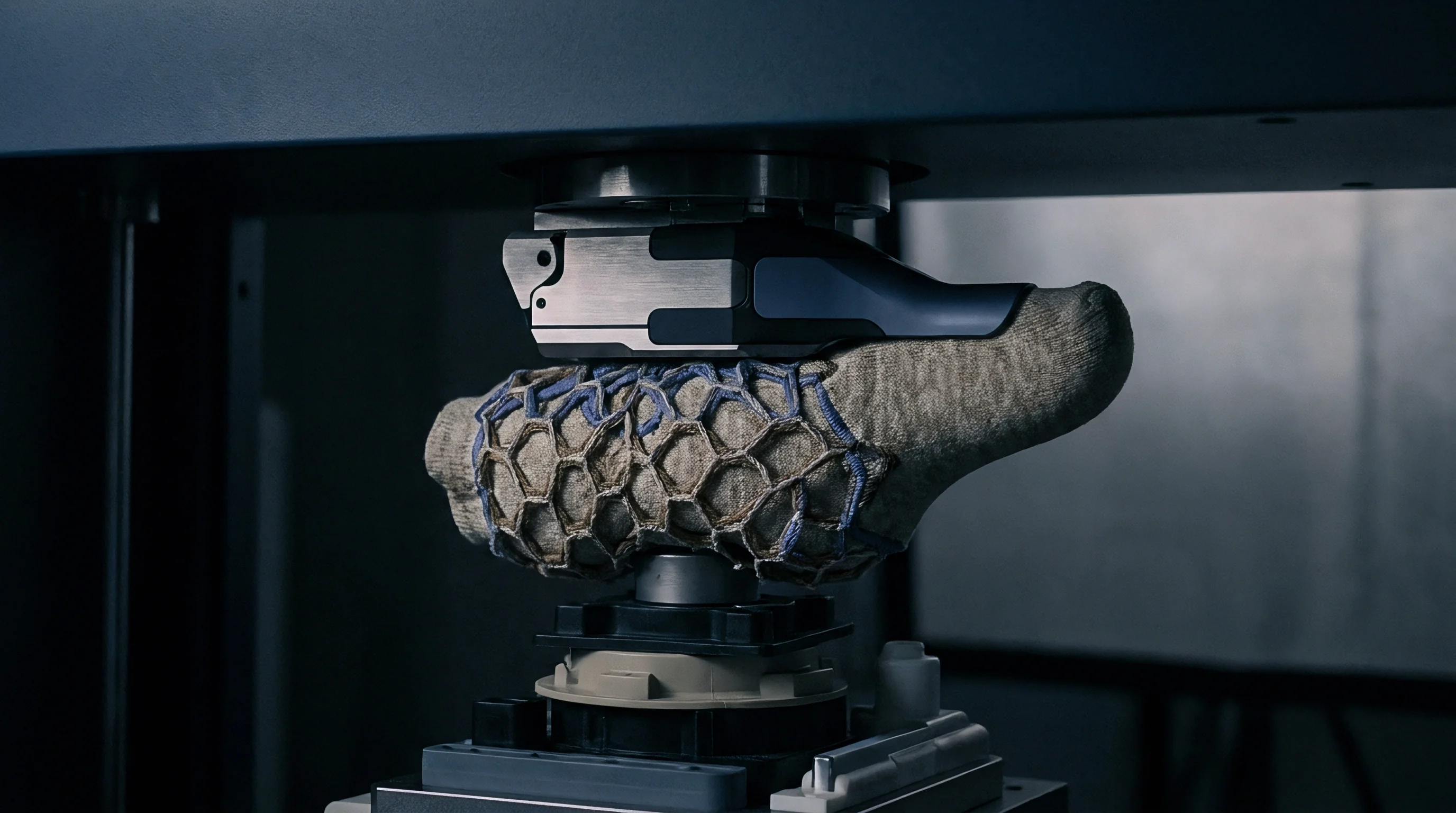
Verifying cam depth adjustments across all cylinder feeds prevents localized stitch length variation. Stitch cam depth dictates the downward travel distance of the needle hook, which directly determines the raw length of yarn drawn into each loop arch. In fine-gauge machines, an adjustment as small as 0.02 millimetres in cam depth alters fabric mass by up to 5 grams per square metre.
Deep stitch cam settings yield longer loops, reducing fabric weight and increasing air permeability, but elevate the risk of yarn distortion and spirality. Conversely, steep, shallow cam profiles tighten the loop structure, raising fabric density and bursting resistance while increasing mechanical wear on needle butts.
Stitch tension governs yield.
Holding-down sinkers must execute precise horizontal movement to clear the old loop from the needle latch while securing the fabric plane against upward motion during needle ascent. When operating with multi-feed circular arrangements, slight mechanical play in the sinker ring creates circumferential yarn length variations. The table below outlines standard structural parameters across fine-gauge single jersey machine configurations using synthetic filament yarns.
| Machine Gauge (E) | Needle Pitch (mm) | Yarn Count (dtex) | Target Loop Length (mm) | Tightness Factor (Kt) |
|---|---|---|---|---|
| E28 | 0.907 | 110 dtex / 72f | 2.85 | 1.46 |
| E32 | 0.794 | 78 dtex / 68f | 2.62 | 1.49 |
| E36 | 0.706 | 56 dtex / 48f | 2.40 | 1.52 |
| E44 | 0.577 | 33 dtex / 36f | 2.12 | 1.58 |

Sinker Timing Relative to Needle Knock Over
Adjusting the angular position of the holding-down ring changes how yarn feeds into the knock-over plane. In synchronized sinker timing, the sinker moves forward simultaneously as the needle completes its downward stitch draw. This simultaneous action exerts high peak tension on the yarn, leading to filament abrasion when processing fine microfibres.
Retarding the sinker movement relative to the needle cylinder cycle, known as delayed sinker timing, allows the needle to draw yarn primarily from the previously formed loop rather than drawing exclusively from the yarn feeder guidance eye.
Delaying sinker interaction reduces yarn tension spikes at knock-over while preventing loop length drift across multifeeder circular machines.
Delayed timing lowers peak knitting tension by fifteen to twenty percent on E36 machinery. This tension reduction yields highly uniform loop limbs and minimizes structural micro-twisting inside the stitch structure. Higher gauges demand finer yarns.
However, excessive delay causes loop sagging and structural drop-stitches, requiring precise dial gauge calibration during machine setup. Knitting machinery suppliers frequently attribute lateral shade bands to lot-to-lot yarn friction coefficient shifts rather than addressing mechanical play within the sinker ring.


Deformation
High-gauge knitted fabrics alter their structural dimensions when mechanical tension redistributes yarn within individual loop arches. The geometrical equilibrium of a knitted stitch depends on the ratio of loop length to thread diameter, alongside the mechanical characteristics of the input yarn. When external forces act upon raw greige fabric off the machine cylinder, the loop heads and feet shift orientation.
Unbalanced structures skew post-wash.

Does Stitch Cam Depth Control Spirality in E36 Knits?
Altering the vertical displacement of cylinder cams directly shifts the amount of yarn drawn into each loop. In single jersey structures knitted with Z-twist or S-twist single spun yarns, the internal torsional torque of the yarn causes the loop limbs to tilt. This tilt manifests macroscopically as fabric spirality, where Wales sit at an angle relative to the perpendicular axis of the fabric roll.
Decreasing stitch cam depth shortens loop length, which increases inter-loop contact friction and locks the loop legs against rotational movement.
Fabric torque drives spirality failures.
Mathematical modeling of loop geometry uses the tightness factor Kt, defined as the ratio of the square root of yarn linear density in Tex to the loop length in centimetres:
Kt = fracsqrtTexl
Assume an E36 single jersey knitted with a 50/1 Ne combed cotton yarn (11.8 Tex). If the stitch cam is set to deliver a loop length l of 0.235 cm, the resulting tightness factor is calculated as:
Kt = fracsqrt11.80.235 = frac3.4350.235 = 1.462
At a tightness factor of 1.462, inter-loop friction is insufficient to counteract the residual yarn twist torque. Laboratory testing under ISO 6330 wash cycles yields a spirality angle of 7.5 degrees, exceeding standard commercial thresholds. If the technician adjusts the stitch cam depth downward to restrict loop length to 0.215 cm, the new tightness factor becomes:
Kt = frac3.4350.215 = 1.598
Elevating Kt to 1.598 increases inter-loop contact force by twenty-eight percent. This mechanical constraint forces the loop legs to remain upright, driving final fabric spirality down to 2.8 degrees post-wash. Tightening the stitch geometry reduces fabric width yield and increases fabric mass per unit area, altering the commercial conversion profile of the order.
A loop length reduction from 2.65 millimetres to 2.48 millimetres on an E32 single jersey machine elevates pneumatic bursting strength from 280 kilopascals to 365 kilopascals under ISO 13938-2 testing.
Plated Elastane Draft Ratios and Structural Recovery
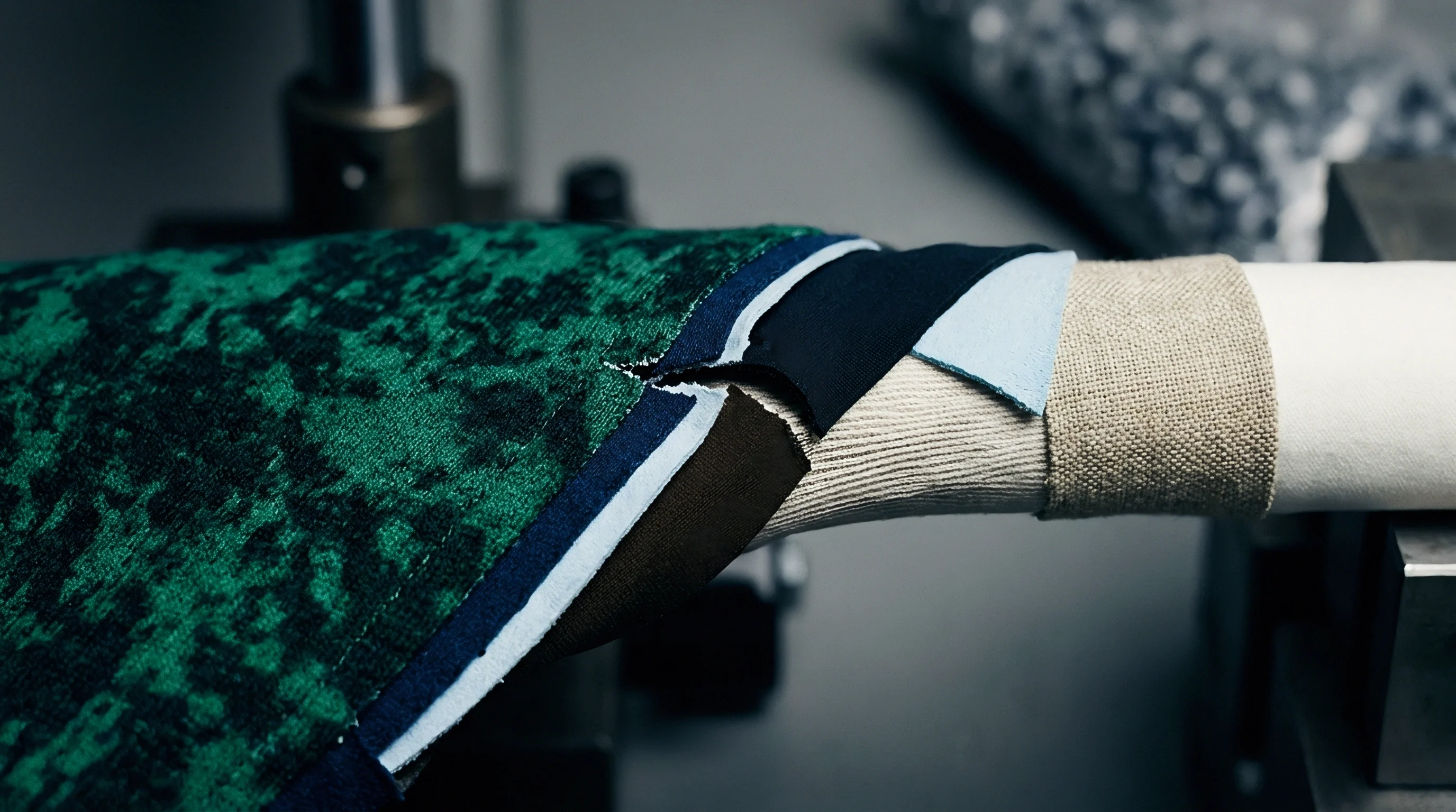
Feeding synthetic elastomeric core yarns under mechanical tension alters the structural density of fine-gauge single jersey. Plated circular knits introduce a bare or single-covered elastane yarn alongside the primary hard yarn, engaging both in the needle hook simultaneously. The elastane draft ratio, controlled via positive feeder pulleys, determines the residual elastic force stored within the relaxed fabric matrix.
Excessive draft breaks elastane filaments.
Knock-over timing alters loop pitch.
Selecting incorrect draft ratios or improper cam profiles produces predictable structural defects across high-gauge production runs. Fabric buyers and quality auditors identify the following mechanical failure modes on finished rolls:
- Loop Shear Displacement occurs when high yarn friction during knock-over distorts loop heads, driving structural spirality above five degrees.
- Elastane Core Exposure manifests when excessive draft ratios snap filament sheaths during stitch formation, leaving bare elastane visible on the technical face.
- Course Distortion Banding arises from uneven storage feeder tension across circular feeds, creating visible horizontal denier variations under light-box inspection.
- Needle Line Streaks result from micro-burrs on latch surfaces that abrade fine filament yarns, lowering pneumatic bursting strength beneath test thresholds.
Greige density dictates dry weight.
Incorrect calculation of loop length parameters before committing to bulk extrusion guarantees dimensional shrinkage exceeding eight percent and drives garment torque past commercial acceptance limits.
Stabilization
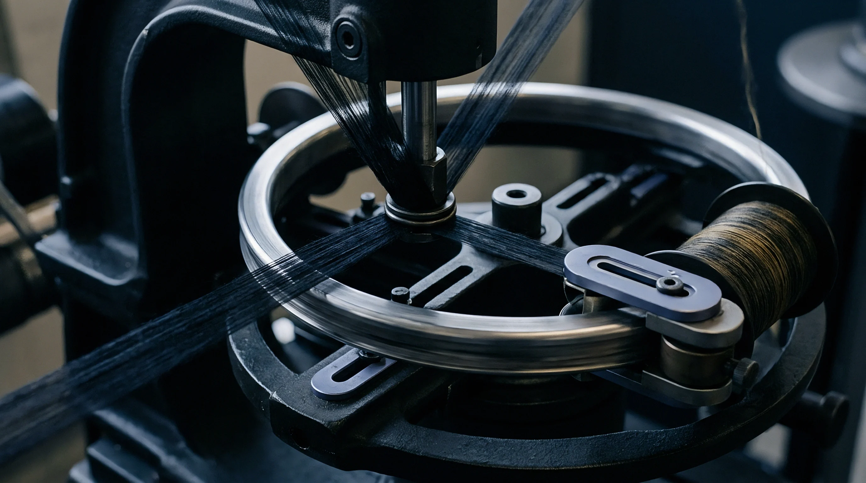
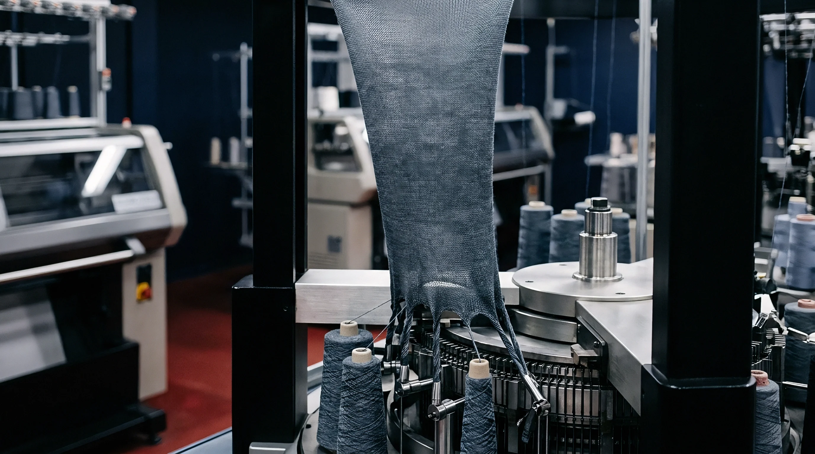
Wet finishing processes reduce internal energy stored within asymmetric loop structures through thermal and hydraulic relaxation. As greige goods roll off circular knitting frames, high residual tension remains locked inside the loop arches due to mechanical pulling forces exerted by take-down rollers. Un-tensioned aqueous relaxation allows loops to revert from an elongated shape to their natural, relaxed configuration.
Skipping adequate relaxation protocols prior to heat fixation locks structural distortions permanently into the synthetic matrix.
Open Width Scouring and Relaxed Drying Protocols
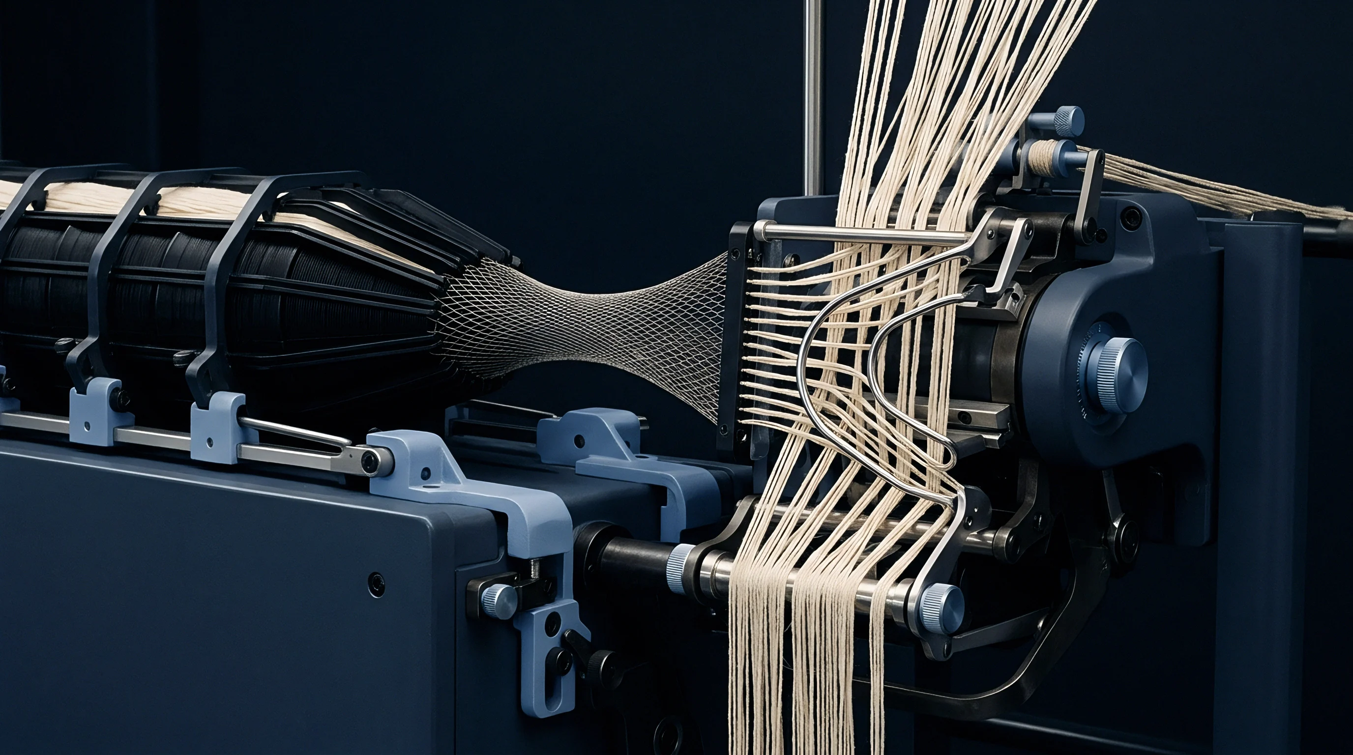
Slitting tubular knit goods prior to aqueous processing prevents permanent creasing along rolled edges. High-gauge goods made from ultra-fine denier yarns are particularly prone to edge-marking and rope-marks if processed in traditional jet dyeing vessels without continuous width-expansion systems. Open-width scouring lines wash out spin finishes, knitting oils, and residual lubricants that would otherwise burn into synthetic fibers during subsequent thermal fixation.
Dyehouse tension alters course counts.
Overfeed restores loop height.
To ensure optimal dimensional stability, wet processing facilities sequence open-width finishing steps in accordance with strict physical relaxation stages:
- Feed raw circular jersey off the knitting floor directly through open-width slitters to relieve internal circular torque prior to wet treatment.
- Subject the slitted roll to continuous aqueous scouring at 75 degrees Celsius with non-ionic surfactant to extract synthetic spinning oils.
- Pass the un-tensioned fabric web through a relaxed suction-drum dryer to achieve full dimensional contraction of the loop arch.
- Mount the fabric on a pin-stenter rail system maintaining twenty percent longitudinal overfeed at 190 degrees Celsius for forty-five seconds.
- Audit finished width and mass per unit area against sample swatches under standard conditioning environments before packaging.
Thermo Fixation and Stenter Overfeed Calibration
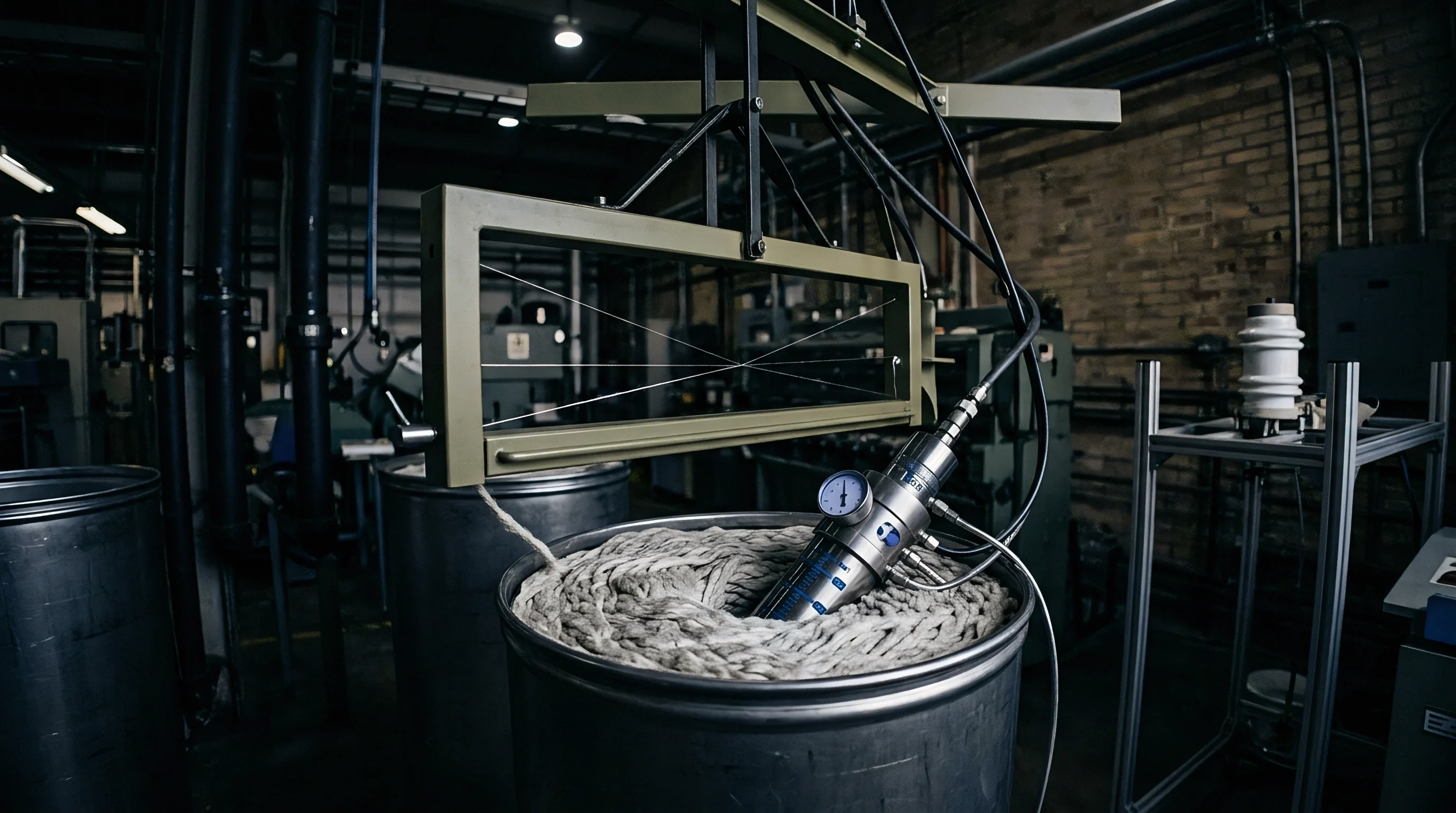
Heat application inside pin-stenter chambers fixes synthetic filament geometry at specified dimensions. Thermo-fixation resets the hydrogen bonds in polyamide or crystalline domains in polyester while setting the elastic recovery threshold of plated elastane yarns. Stenter overfeed calibration determines whether finished loop structures sit in a neutral tension state or retain residual longitudinal strain.
Thermal setting locks loop geometry.
Applying longitudinal overfeed forces the fabric web onto the pin chains at a linear speed greater than the chain travel speed. This excess length allows the course density to increase while loop heads relax into a rounded, stress-free configuration. The table below details heat-setting parameters for fine-gauge elastomeric jersey builds.
| Substrate Blend | Setting Temperature (°C) | Dwell Time (s) | Stenter Overfeed (%) | Target GSM Range | Residual Shrinkage (ISO 5077) |
|---|---|---|---|---|---|
| 80% Polyamide 6.6 / 20% Elastane (E36) | 192 | 40 | +22% | 160 – 170 | < 2.5% |
| 85% Polyester / 15% Elastane (E32) | 185 | 45 | +18% | 180 – 190 | < 2.0% |
| 92% Combed Cotton / 8% Elastane (E28) | 165 | 35 | +15% | 200 – 210 | < 3.0% |
| 100% Micro-Polyamide 6.6 (E44) | 195 | 30 | +25% | 110 – 120 | < 1.5% |
Contracts incorporating ISO 6330 washing procedure 4N mandate dimensional stability thresholds below three percent, forcing dyehouses to maintain longitudinal stenter overfeed between eighteen and twenty-two percent.
Mandating adherence to ISO 3759 specimen preparation specifications inside purchase agreements forces dyehouses to re-qualify stenter speed parameters whenever greige loop densities shift by more than two courses per centimetre.

Verification
Standardized laboratory testing confirms whether physical performance attributes align with written contract requirements. Fine-gauge knitted constructions alter failure mechanisms compared to traditional coarse fabrics. The reduced cross-sectional diameter of individual yarns combined with elevated stitch densities alters load distribution across adjacent loop arches during multidirectional tensile stress.

Bursting Strength and Abrasion Test Methodologies
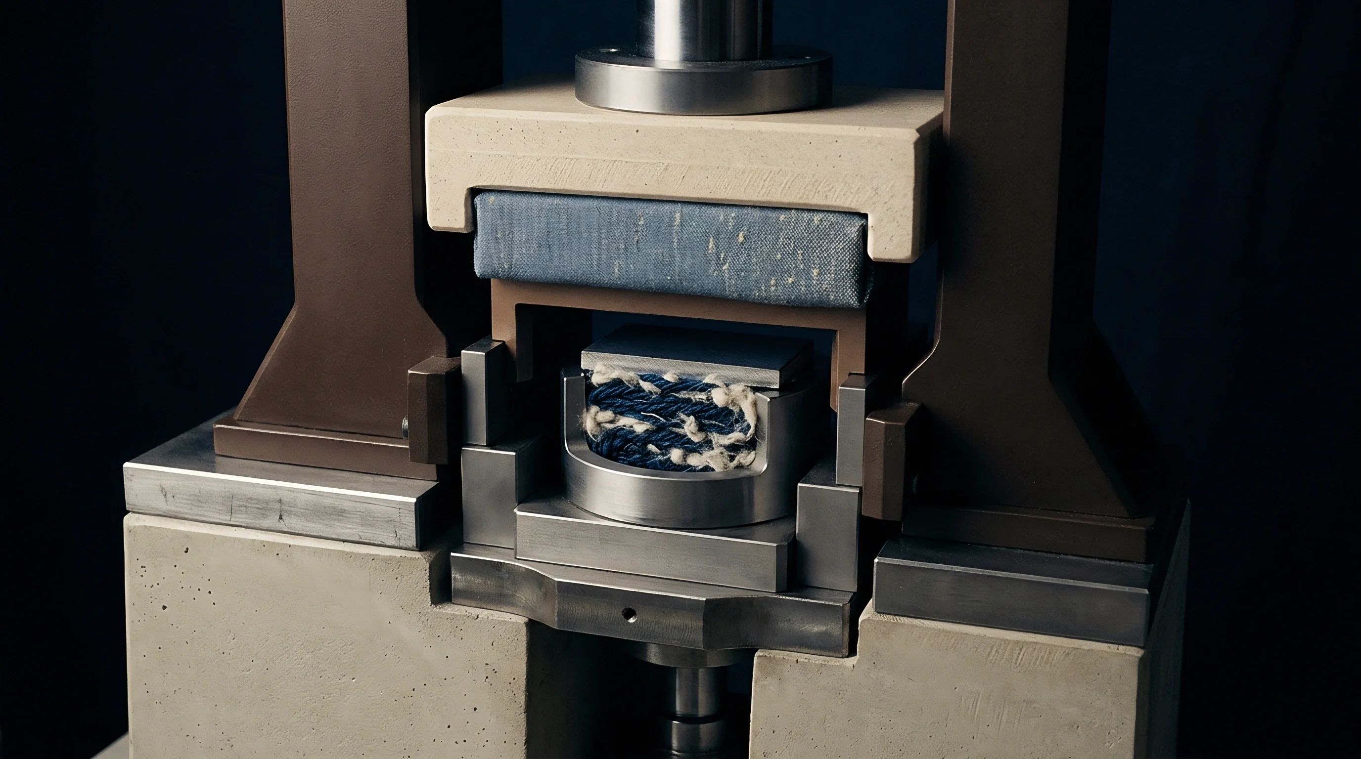
Evaluating physical durability requires multidirectional force application to measure loop yield limits. Pneumatic bursting strength testing under ISO 13938-2 applies fluid pressure beneath a flexible rubber diaphragm clamped over a circular test area of 7.3 square centimetres. Fine-gauge fabrics resist initial pressure through loop head distortion, distributing stress across a high number of stitches per square centimetre.
When loop tightness is too low, yarn sliding occurs before failure, causing premature tearing along needle Wales.
Pneumatic pressure measures burst capacity.
Martindale pilling resistance per ISO 12945-2 assesses surface fiber disruption under controlled translational motion. High-gauge single jersey structures using low-twist micro-denier yarns present increased surface area to abrasive contact. Tightening loop geometry via stitch cam adjustments increases loop density, which restricts free fiber ends from migrating out of the yarn core under surface friction.
Dimensional Skewing and Course Density Audits
Counting Wales and courses per unit length reveals greige structural changes across finishing stages. Dimensional stability audits apply ISO 5077 test methods involving controlled domestic laundering per ISO 6330 followed by flat drying. Specimen dimensions are marked prior to washing, and percentage dimensional change is calculated along both course and Wales directions.
Quality control teams utilize specific acceptance frameworks when evaluating high-gauge technical knit specifications:
- Pneumatic Bursting Qualification requires five test specimens exposed to a 7.3 square centimetre test area under ISO 13938-2 to confirm structural integrity across high-gauge loop arches.
- Martindale Pilling Resistance evaluation under ISO 12945-2 demands 2,000 rubs under a nine kilopascal load, setting a minimum passing threshold of grade four for activewear builds.
- Spirality Measurement Protocols follow ISO 6330 laundry procedures, measuring course angle deviations against perpendicular grid marks to flag torque values exceeding three degrees.
- Mass Per Unit Area Verification according to ISO 3801 requires circular cutter sampling across three distinct roll zones, enforcing a strict zero-plus-minus-five-percent gsm tolerance.
Fine gauge knitted structures exhibit heightened sensitivity to stenter pin tension, where unequal selvedge draft creates asymmetrical pilling resistance across the cuttable width.
Evaluating loop geometry under optical magnification before running wet finishing trials prevents premature dyehouse adjustments on inherently unbalanced greige builds.

Economics
Commercial viability in fine-gauge knit production depends on balancing machine throughput against yarn breakage frequency. Converting circular knitting plants from standard E28 machinery to E36 or E44 cylinders introduces significant capital outlay for specialized needle beds, high-precision sinker rings, and controlled-atmosphere clean rooms to manage lint contamination. Operating ultra-fine gauges reduces output volume in kilograms per machine hour, increasing conversion costs per linear metre.
Yarn friction limits machine speed.
Machine Speed Trade Offs and Yarn Breakage Costs
Operating circular cylinders at elevated rotational velocities increases friction forces on fine needle hooks. As machine cut increases, needle latch dimensions shrink, reducing impact tolerance during high-speed cam interaction. Operating an E28 circular machine at 28 revolutions per minute generates acceptable needle wear and low defect rates.
Elevating machine gauge to E44 forces cylinder rotation down to 16 revolutions per minute to limit thermal expansion of the needle ring and prevent needle breakage.
Thicker yarns increase needle wear.
Consider a sourcing scenario evaluating production costs across three gauge levels on identical 30-inch diameter single jersey circular frames equipped with 96 feeders. Assume a base factory operating efficiency of 85 percent, direct machine labor costs of $12.50 per hour, and raw yarn input cost scaled to yarn denier fineness. The breakdown illustrates how output drop-off impacts finished fabric unit pricing.
| Machine Gauge (E) | Max Cylinder Speed (RPM) | Yarn Linear Density | Output Yield (kg/24h) | Knitting Conversion Cost ($/kg) | Landed Fabric Price ($/m) |
|---|---|---|---|---|---|
| E28 | 28 | 110 dtex | 385 | $1.85 | $4.20 |
| E32 | 24 | 78 dtex | 290 | $2.45 | $5.60 |
| E36 | 20 | 56 dtex | 210 | $3.40 | $7.85 |
| E44 | 16 | 33 dtex | 135 | $5.30 | $12.40 |

Capacity Constraints across Fine Gauge Mills
Factory allocations for E36 and E44 machinery remain concentrated among specialized commission knitters. The high capital expenditure required for E44 conversion limits global capacity, creating bottlenecks during peak production cycles. Buyers specifying ultra-fine gauge knits commit to extended lead times, often adding four to six weeks to greige fabric availability compared to standard E28 builds.
High gauge orders commit specialized machinery capacity.
When yarn quality falls below stringency parameters, micro-denier filament breakage increases machine downtime. A single broken filament tail wraps around adjacent needles, generating linear drops that invalidate entire fabric rolls under four-point inspection systems. The resulting scrap rate increases production cost per cuttable metre, eroding converter margins on fixed-price buyer contracts.
Whether ultra-fine E50 circular machinery can achieve commercial viability without custom synthetic filament lubricants remains an open dilemma across European and Asian knitting centers.