Warp Beam Tension Balancing in High Gauge Tricot Knitting
Balancing high gauge tricot warp beam tension within narrow cN per tex bands eliminates fabric weight drift and dynamic horizontal streak defects across bulk runs.
Draft
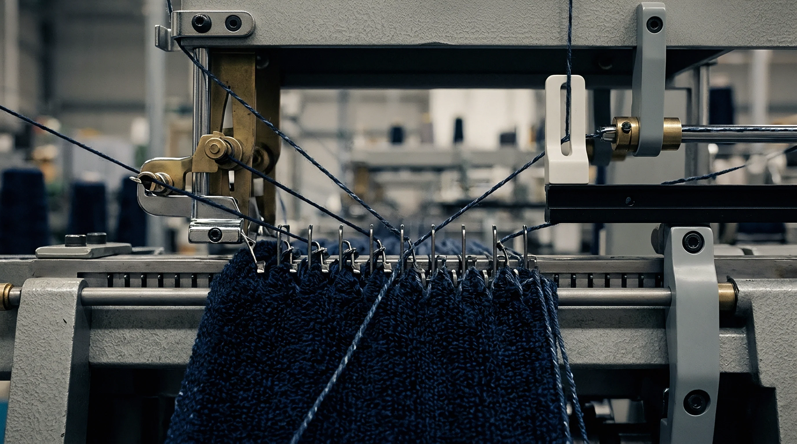
Feeding filament yarn into fine gauge tricot machinery requires precise mechanical delivery to maintain uniform loops across the working width. At E32, E36, and E40 cuts, clearances are tight enough that minor shifts in pull force distort loop formation. When synthetic filaments such as polyamide 6.6 or polyester pass through guide bars at high speed, warp beam delivery dictates fabric weight, stitch density, and visual uniformity.
On an E36 machine (36 needles per inch), each needle occupies a nominal space of 0.705 millimetres, leaving a hook gap under 0.25 millimetres. At this scale, uncontrolled tension fluctuations lead to needle misalignments, broken filaments, and horizontal shading in the fabric.
Warp Delivery Mechanics in Ultra Fine Tricot Machines
Unwinding continuous filament yarns at E32, E36, or E40 machine densities causes steady changes in linear feed speed. A warp beam with an 800-millimetre outer flange diameter and a 150-millimetre steel core presents a 5.33 to 1 radius ratio from full to empty. Operating at 2800 revolutions per minute, the outer surface speed must decelerate continuously to match the needle bar’s loop consumption.
For a 22-dtex 7-filament polyamide warp at 2800 revolutions per minute on an E36 machine, feed rate depends on stitch structure. In a standard two-bar tricot running 1-0 / 1-2 front bar and 1-2 / 1-0 back bar motions, yarn consumption per 480-course rack ranges between 1400 millimetres and 2200 millimetres based on stitch density. Linear draft calculations convert this feed rate into specific target forces.
Thread tension is given in centinewtons per tex, where one centinewton per tex equals 0.111 centinewtons per decitex. Fine polyamide filaments run cleanly between 1.5 and 3.0 cN/tex. On a 22-dtex yarn, a setting of 2.0 cN/tex translates to an individual thread force of 4.4 centinewtons.
Across a 130-inch wide E36 frame carrying 4,680 ends per guide bar, those individual forces total 20.6 newtons of pull on the warp beam. Maintaining this total force across package depth is essential. As effective beam diameter shrinks from 800 millimetres to 150 millimetres, torque transferred to the spindle drops proportionally.
Without active intervention, passive braking causes thread tension to jump sharply near the core. A tension rise from 2.0 cN/tex to 4.5 cN/tex stretches synthetic filaments past their elastic limit, inducing permanent elongation. Polyurethane elastomeric yarns, such as 22-dtex or 44-dtex threads, are particularly susceptible to these surges, experiencing draft shifts that compromise fabric elasticity, yield mass, and finished width.
Linear Tension Variations across High Gauge Beam Sets
Unwinding a packed beam continuously shifts its working radius and alters mechanical leverage across the sheet. High-gauge warping aligns thousands of parallel ends onto precision-ground aluminium beams under tight control, yet density gradients formed during warping frequently introduce localized variation. Yarn near outer flanges packs tighter laterally than yarn at the center.
When mounted on the tricot machine, these package variations produce cross-beam tension differentials that alter runner lengths across the sheet. Runner length represents the millimeter length of yarn consumed by a guide bar over a standard 480-course rack. On an E36 machine knitting activewear mesh or fine lingerie tricot, a nominal front bar runner length of 1680 millimetres per rack must remain within plus or minus 5 millimetres across all sections.
If edge sections draw at 3.2 cN/tex while the center feeds at 2.1 cN/tex, the tighter edges take up shorter runner lengths, forming compact loops at the sides while center threads form loose, elongated ones.
A tension variance exceeding 0.3 cN/tex across an E36 warp beam causes measurable wale density fluctuations beyond 4 percent in finished greige fabric.
Friction along the yarn path compounds these tension differences. Thread guides, spring bars, and separators create cumulative drag defined by the capstan equation, where output tension depends on the friction coefficient between synthetic yarn and polished ceramic or steel multiplied by total contact angle in radians. A ceramic guide post with a friction coefficient of 0.18 and a 90-degree bend increases yarn force by 32 percent across that single point; across complex guide setups, accumulated drag can double the tension reaching the needle bar.
Force balance calculations illustrate why dynamic control is necessary. Running a 130-inch wide E40 machine with 5,200 ends per guide bar on 15-dtex polyamide requires stable conditions. At a baseline target of 1.8 cN/tex, individual thread force sits at 2.7 centinewtons, yielding a total bar tension of 14.04 newtons.
If mechanical drag adds just 5.0 newtons from uncompensated beam deceleration or guide friction, single-thread tension climbs to 2.44 cN/tex. That 35 percent increase reduces loop height, increases fabric weight from a target 110 grams per square metre up to 122 grams per square metre, and narrows usable width after scouring and heat setting. Left uncorrected, beam tension fluctuations cause yield losses, horizontal dye streaks from strain variations, and needle breakage under high knock-over loads.
Drive
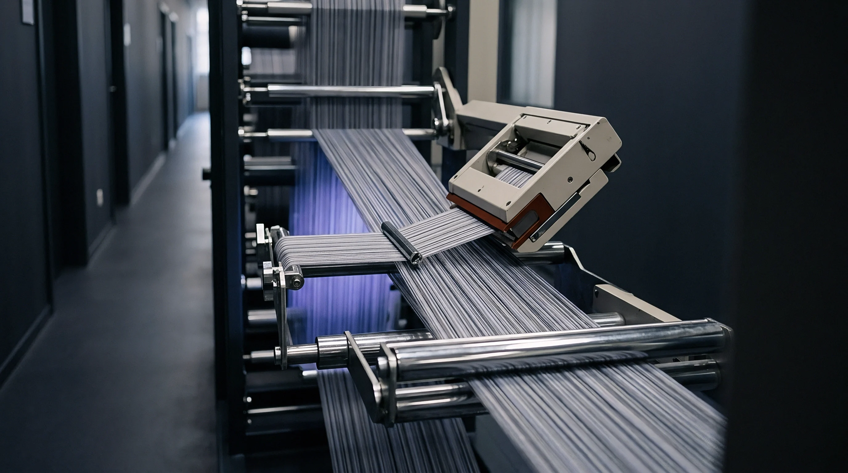
Modern high-gauge tricot machines replace mechanical friction brakes with brushless motors and digital drives. Accurate warp feeding requires continuous adjustment of beam rotation speed to match needle bar consumption millisecond by millisecond. Closed-loop electronic let-off systems (EBA or EFA) monitor mainshaft velocity and yarn sheet position, recalculating required spindle angular speed on the fly.

Electronic Let off Synchronization and Servo Feedback
Brushless AC servomotors directly coupled to worm gearboxes drive individual beam spindles under closed-loop control. Mainshaft encoders supply positional data, generating between 4,096 and 16,384 pulses per revolution. The let-off controller uses these pulses to compute real-time knitting speed and guide bar cycle rates.
As the machine ramps from zero to 3000 revolutions per minute during acceleration, the let-off drive accelerates beam spindles in sync to prevent yarn stretching or slack. Response timing is critical. Digital loops process feedback signals within sampling windows of 1.0 to 2.5 milliseconds, comparing target runner lengths per rack against actual beam rotation angles.
Spindle-mounted optical or magnetic proximity sensors track angular movement to fractions of a degree. By monitoring beam rotation against mainshaft course counts, the controller recalculates effective package diameter continuously. If yarn tension drops due to changing beam diameter or speed mismatch, the drive increases servomotor speed to restore equilibrium.
Dynamic braking modules dissipate regenerative energy during sudden stops, preventing beam over-travel that causes slack loops and tangled warp sheets.

Dynamic Load Cell Measurement and Signal Damping
Continuous tension monitoring relies on piezoelectric or strain-gauge sensors mounted at the ends of the warp spring bar. As yarn passes over the rail, collective sheet forces displace the bar by micrometre increments. Strain gauge transducers convert this movement into proportional analogue signals ~ typically 0 to 10 volts or 4 to 20 milliamperes ~ representing aggregate yarn force across full width.
Downstream electronics filter out transient high-frequency noise generated by guide bar motion. Guide bar swings induce cyclic force spikes at harmonics of operating speed; at 3000 rpm, the primary guide bar frequency reaches 50 Hertz. Without low-pass filtering and signal damping, these 50 Hz spikes trigger harmonic oscillations in the servo loop, forcing the beam motor to hunt and surge.
Damping algorithms apply digital Butterworth or Bessel filters tuned to cut off frequencies above 15 Hertz while preserving genuine tension drift signals.
| Machine Gauge | Yarn Type & Count | Target Tension (cN/tex) | Filter Cutoff (Hz) | Sampling Rate (kHz) | Target Runner (mm/rack) | Let-Off Accuracy (%) |
|---|---|---|---|---|---|---|
| E28 | Polyester 44dtex f13 | 2.2 ± 0.15 | 20 | 1.0 | 1580 ± 3 | ± 0.15 |
| E32 | Polyamide 33dtex f10 | 2.0 ± 0.12 | 18 | 1.5 | 1620 ± 3 | ± 0.12 |
| E36 | Polyamide 22dtex f7 | 1.8 ± 0.10 | 15 | 2.0 | 1680 ± 2 | ± 0.10 |
| E40 | Polyamide 15dtex f7 | 1.5 ± 0.08 | 12 | 2.0 | 1740 ± 2 | ± 0.08 |
| Data acquired under standard laboratory conditioning at 20°C ± 2°C and 65% ± 4% RH; mainshaft operating speed constant at 2800 rpm across all test runs. | ||||||
Calibrating load cell response curves requires zero-point balancing before threading yarn. When mounting new or empty beams, mechanical tare weight is zeroed in controller memory, and sensitivity coefficients are scaled in centinewtons per millivolt for accurate digital conversion. When periodic barring appears in finished fabric, electrical drive operation can remain strictly within tolerance while dimensional variations originate from raw yarn shrinkage or improper stenter overfeed settings in the dyehouse.
Deflection
Heavy steel beam barrels undergo elastic bending under high winding tension from synthetic filament sheets. In high-gauge tricot knitting, this deflection alters yarn delivery geometry, creating uneven path lengths between the beam surface and tension spring bar across the machine. An 84-inch or 130-inch beam loaded with thousands of ends acts as a simply supported beam under uniform load, flexing most at the midpoint.
Tension Spring Bar Dynamics and Deflection Profile
Flexible sensor rails absorb high-frequency tension pulses created by guide bar swing during loop formation. The spring bar rail ~ built from extruded aluminium or carbon-fiber composite ~ mounts on precision leaf springs or torsion bars. As guide bars swing through the needle bed to wrap thread around compound needle hooks, yarn path length changes continuously during each revolution.
The spring bar flexes forward during peak tension at guide bar overlap, then releases stored energy to take up slack on the return stroke. Tuning spring bar stiffness requires keeping its natural resonant frequency away from machine operating speeds. If spring bar resonance matches needle bar frequency at 2800 to 3200 rpm, rail bounce becomes uncontrolled, sending severe tension surges through the yarn sheet that distort loops and break filaments.
Viscous hydraulic dampers or elastomeric friction blocks dampen spring bar response without initiating self-sustaining vibration. Mechanical deflection of the warp beam barrel presents a separate spatial issue. Under a total yarn load of 250 N across a 130-inch beam, the center of the steel barrel sags downward by up to 0.85 millimetres relative to the rigid flanges.
This sag creates a shallow concave profile across the wound yarn sheet, reducing effective barrel radius at the center. Consequently, center yarn ends pay out at a slightly different linear speed than flange ends, creating persistent wale density gradients across the fabric.
Runner Length Measurement and Rack Verification
Standard industry protocols measure thread consumption over a fixed block of 480 machine revolutions, universally called a rack. Verifying runner length involves tracking yarn length through a calibrated measuring wheel or optical encoder over exactly one rack cycle. Establishing warp tension baseline targets depends on yarn linear density and filament count.
Checking runner lengths across multiple positions on the beam sheet verifies balanced tension. Runner length per rack governs basic structural parameters: Runner Length (mm/rack) = fracTotal Yarn Feed Length per RackNumber of Racks Standard verification requires strict execution to keep baselines consistent across beam changes:
- Calibrate load cell amplifiers with static deadweights prior to beam mounting.
- Check flange distance and shaft runout using a dial indicator.
- Thread yarn sheets through tension spring bars without crossing ends.
- Set initial electronic let-off ratio based on calculated runner length per rack.
- Run a 480-course trial at 500 rpm to measure actual runner consumption.
- Adjust servo trim pots to eliminate runner differentials between ground and pattern beams.
Tension logs document compliance, while continuous digital tracking prevents runner length drift over multi-day production runs.
Compliance with DIN 53835 for elastomeric warp yarn tension testing mandates dynamic load evaluation at 100 percent extension to prevent off-shade bands in finished garments.
Could Automated Sensor Feedback Prevent Barrel Bowing Errors?
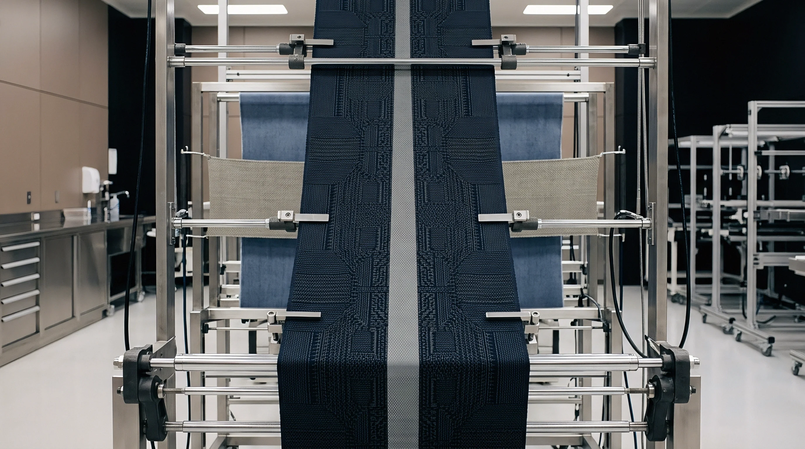
Integrating multi-zone optical scanners along the yarn sheet allows real-time detection of density gradients before stitch variations appear. Advanced arrays measure linear yarn velocity across eight distinct zones along the beam width. When optical sensors detect center ends paying out 0.3 percent faster than flange ends due to barrel bowing, feedback signals send adjustments to multi-segment spring bars or linear actuators.
Segmented spring bar mechanisms alter localized rail positions, dynamically shortening or lengthening the yarn path to offset barrel deflection. While single-zone electronic let-off drives manage only average tension across the sheet, multi-zone sensing targets localized physical variations. Compensating for multi-zone dynamic deflection eliminates edge-to-center tension gradients, preserving uniform runner lengths across 130-inch and 218-inch working widths.
Whether automated multi-zone systems can become cost-effective for commercial mills running on narrow margins remains an open question.

Sinker
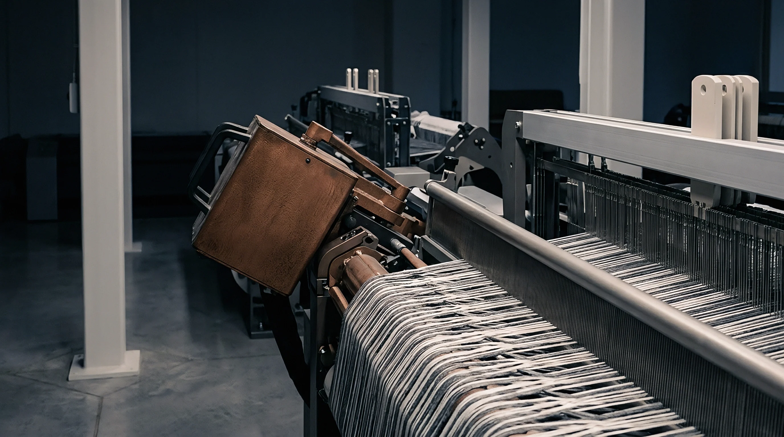
Loop formation depends on exact spatial interaction between ascending needles, descending yarn guides, and thin holding-down sinkers. Sinkers play a dual role in tricot knitting: holding down previously formed loops as needles rise, and providing a ledge over which new loops form and knock over.
On high-gauge E32, E36, and E40 machines, sinker thickness shrinks to 0.18 millimetres, 0.14 millimetres, and 0.11 millimetres. At those dimensions, excessive warp tension causes mechanical deflection of sinker nibs and throats, driving premature wear and stitch distortion.
Loop Formation Forces and Sinker Penetration Timing
Operating speeds over 2500 cycles per minute generate brief force peaks inside every thread loop. As guide bars execute shog and swing movements to wrap yarn around compound needle hooks, tension spikes sharply. The sinker moves forward to hold the fabric loop low on the needle stem, keeping fabric from riding up with the ascending needle.
Sinker throat clearance is critical: if warp tension is too high, yarn pulled over the sinker throat exerts high contact pressure, wearing micro-grooves into thin sinker edges that quickly shred delicate 15-dtex filaments. If tension is too low, loose loops collapse as the sinker advances, creating dropped stitches, double loops, and holes. Dynamic strain diagrams show that loop formation forces follow a non-linear curve during each 360-degree cycle, peaking during knock-over when the needle wire seals the hook and descends below the knock-over plane to draw new yarn through the previous loop.
Knock over Tension Spikes in Fine Gauge Needle Beds
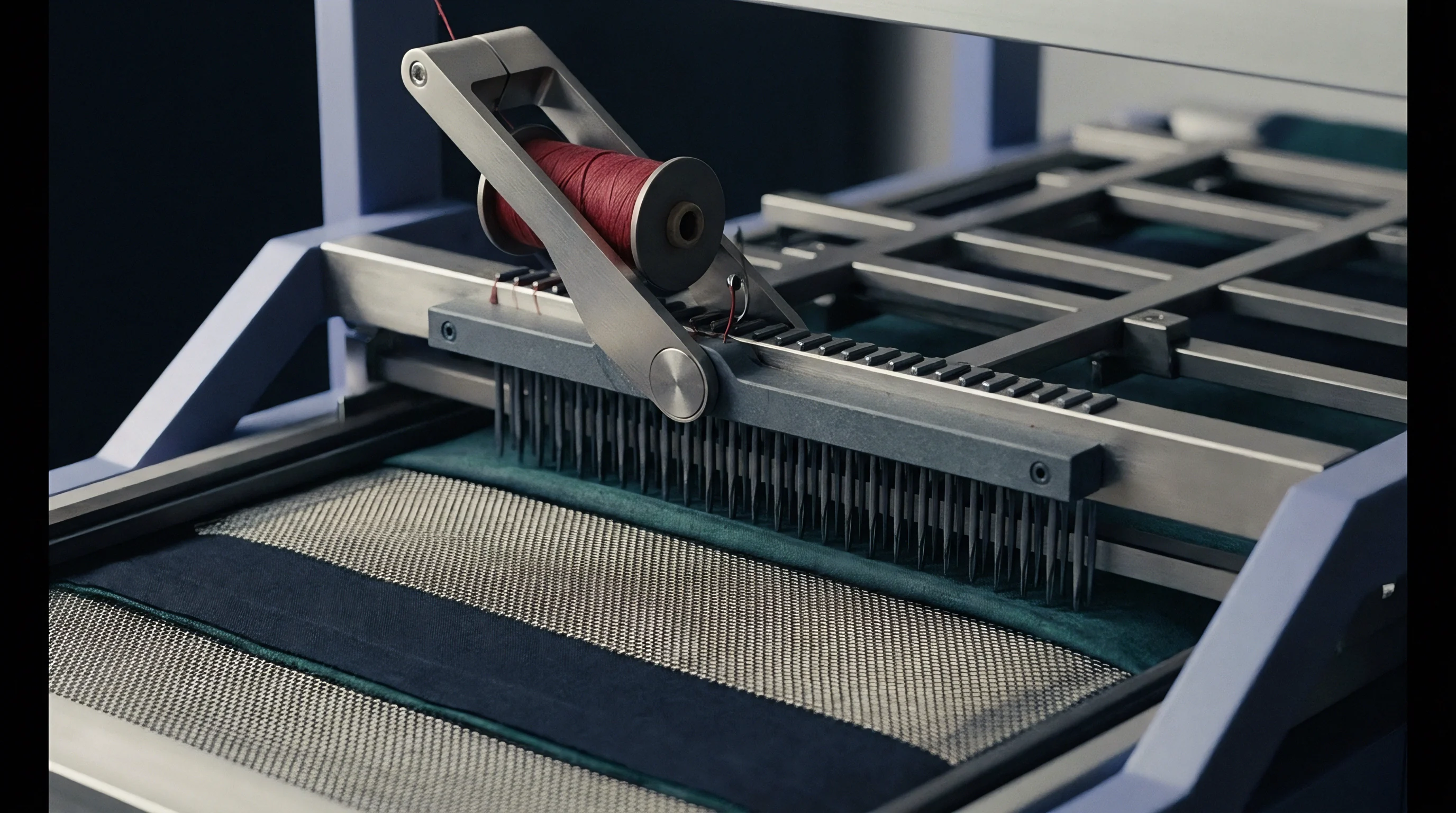
Tensile force reaches its maximum when the needle hook draws new thread through the prior stitch. On an E36 machine running 22-dtex polyamide, individual thread tension spikes from a baseline running level of 2.0 cN/tex up to dynamic peak values between 6.8 and 8.5 cN/tex during knock-over ~ a pulse lasting under 2.0 milliseconds per cycle. If peak dynamic force exceeds yarn yield strength, micro-filaments snap, leaving fine fuzzy slubs on the fabric surface.
In ultra-fine meshes and elastic tricot, these broken filaments degrade surface smoothness and lower bursting strength after dyeing.
| Gauge | Needle Hook Gap (mm) | Sinker Thickness (mm) | Yarn Linear Density | Baseline Tension (cN/tex) | Peak Knock-Over Spike (cN) | Filament Damage Threshold (cN) |
|---|---|---|---|---|---|---|
| E28 | 0.32 | 0.22 | 44 dtex f13 | 2.2 | 12.5 | 18.0 |
| E32 | 0.28 | 0.18 | 33 dtex f10 | 2.0 | 9.2 | 14.0 |
| E36 | 0.22 | 0.14 | 22 dtex f7 | 1.8 | 6.8 | 9.5 |
| E40 | 0.16 | 0.11 | 15 dtex f7 | 1.5 | 4.2 | 6.0 |
Balancing warp tension requires adjusting let-off parameters so baseline force stays low enough to minimize knock-over spikes while maintaining enough control for smooth threading and clean loop formation.
Higher warp tension always pulls loop heads tight while flattening stitch density across adjacent courses.
Fine-tuning sinker timing relative to needle bar stroke modifies peak tension profiles without changing total yarn feed rate. Advancing sinker movement by 2 degrees of mainshaft rotation relieves thread pinching during needle descent, smoothing dynamic force curves and reducing peak spikes by up to 15 percent on fine-gauge setups.
Asymmetry
Running two or three warp beams simultaneously on one frame introduces compound strain differences when mixing stitch structures.
Multi-beam high-gauge tricot machines use separate guide bars (GB1, GB2, and optionally GB3) fed by independent beams. Because each guide bar executes distinct overlap and underlap movements, thread consumption rates per rack vary across bars. Ground fabrics, stretch tricot, and power-net structures depend on maintaining strict, stable runner length ratios between ground and pattern beams.
Dual Beam Ratio Balancing for Ground and Inlay Structures
Front guide bars executing long tricot or atlas laps consume far more yarn per rack than rear bars forming short pillar stitches. In a standard two-bar elastomeric tricot, ground bar GB1 might run a 1-0 / 1-2 lay-in consuming 1680 millimetres per rack, while rear bar GB2 threading 44-dtex elastomeric yarn executes a 1-2 / 1-0 movement consuming 620 millimetres per rack, giving a runner length ratio of 2.71 to 1. Evaluating fine-gauge tricot structures requires tracking runner length variations across full production racks.
Preserving this ratio requires proportional electronic synchronization between beam drives. If rear beam tension drifts up and cuts GB2 runner length from 620 millimetres to 590 millimetres, the runner ratio shifts to 2.84 to 1 ~ a shift that drastically alters internal fabric stress. Unbalanced tension creates severe geometric instability in greige fabric.
If front ends pull under high tension while back elastomeric ends stay loose, the finished fabric curls along cut edges, skews longitudinally, and bows across the width. While overfeed settings during finishing can fix mild edge curling, severe ratio imbalances cause permanent structural flaws that stenter frames cannot rectify.
Differential Shrinkage and Fabric Skew in Dyeing
Unbalanced elastic recovery forces between warp threads cause significant width loss and diagonal torque during wet thermal processing. Scouring, relax washing, and high-temperature jet dyeing release residual stresses locked into the fabric during knitting. High tension stored in ground polyamide threads drives thermal shrinkage up to 8 to 12 percent at 130 degrees Celsius, whereas loose threads undergo minimal contraction.
These differential shrinkage forces trigger four main structural failure modes in commercial fabrics:
- Runner length drift where electronic let-off speed shifts relative to mainshaft revolutions, altering stitch density and fabric weight mid-roll.
- Elastomeric creep where pre-drafted spandex threads recover inside guide bar eyes, causing periodic yarn gathering and horizontal elastomeric bands.
- Beam flange binding caused by axial displacement of beam shafts under unequal lateral spool pressures, creating mechanical drag and periodic let-off hesitation.
- Asymmetric loop distortion where unbalanced thread tensions tilt compound needle loops diagonally, distorting square wale-course geometry into parallelogram skew.
Varying warp tension by 0.5 cN per tex shifts fabric mass by 4.2 percent. Fabric density rises from a target 120 g/m² to 125 g/m², while usable width shrinks by 6.5 centimetres across a 160-centimetre working specification.
A minor mismatch in dual beam runner lengths alters fabric width instantly during stenter drying.
Supply contracts for high-gauge elastic fabrics typically include strict clauses governing warp feed tolerances. Master agreements routinely specify that runner length deviation across multi-beam setups cannot exceed plus or minus 0.75 percent from approved spec sheets, penalizing mills for non-compliant fabric width, weight, or elastomeric recovery.
Discrepancy
Off-spec fabric properties usually surface only after greige goods undergo scouring, heat setting, and piece dyeing.
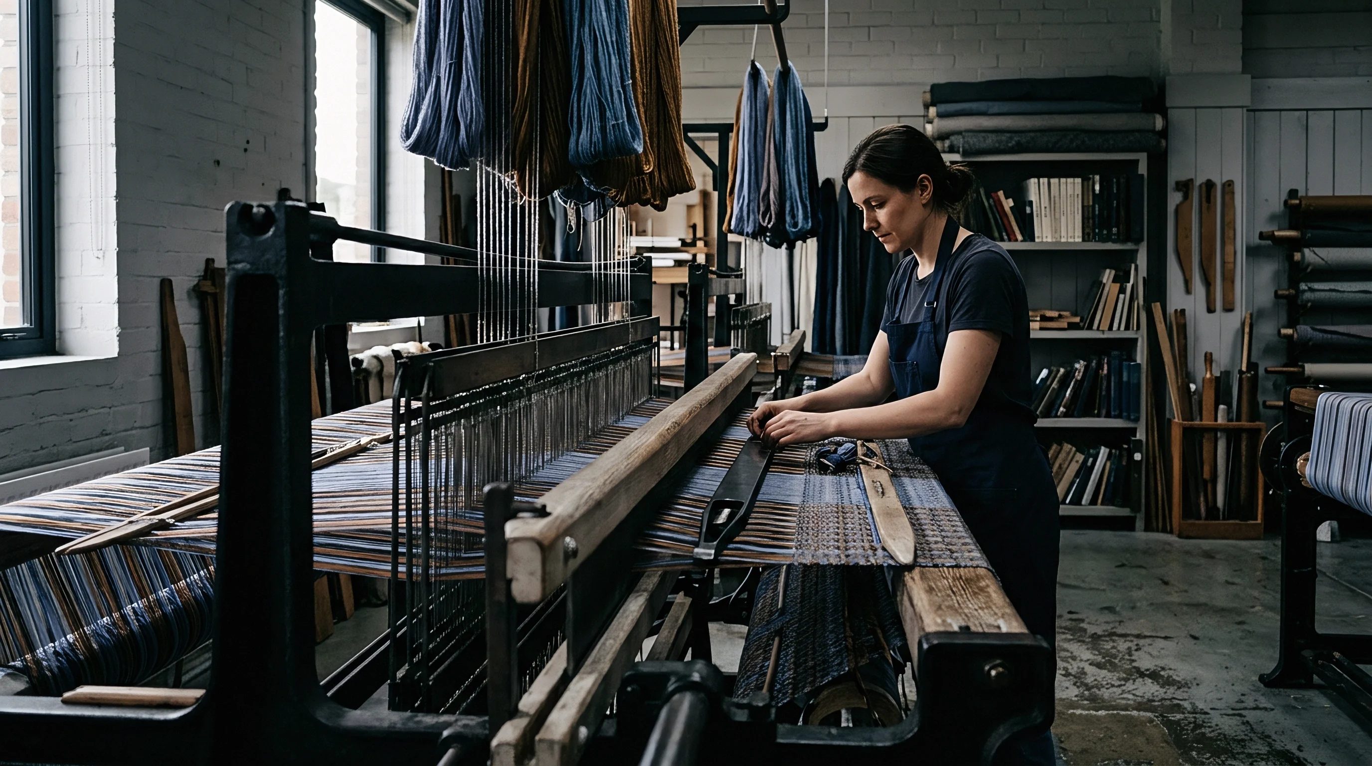
Warp beam tension imbalances that pass unnoticed at the knitting machine manifest as visual, physical, and dimensional defects during final inspection. Because wet processing relieves latent strains in knitted loops, minor let-off fluctuations turn into visible horizontal bars, cloudy shading, edge curling, and significant shifts in fabric weight.
Quality Defect Mapping and Four Point Inspection Thresholds
Horizontal barring and shade bands from periodic let-off fluctuations result in heavy penalties under visual grading standards. The ASTM D5430 Four-Point System assigns penalty points based on defect length: up to 3 inches incurs 1 point; 3 to 6 inches, 2 points; 6 to 9 inches, 3 points; and over 9 inches, 4 points. Continuous barring across the width accumulates 4 points per linear yard, quickly pushing rolls past acceptable quality limits.
To pass as First Quality, a roll must stay below 20 to 28 total penalty points per 100 square yards, depending on buyer specs. A single 50-metre roll with let-off barrings every 2 metres accumulates over 100 points, triggering immediate rejection, downgrade to Second Quality, and price markdowns between 30 and 50 percent. Visual shading stems from microscopic variations in yarn packing density.
Where warp tension was high, loops are small and tight, reflecting more light. Where tension was low, loops are larger and more open, absorbing light differently and altering perceived color depth. Under standard lightbox illuminants like D65, TL84, and CWF, these density variations show up as light and dark bands that fail shade matching.
Commercial Yield Impact and Cost per Finished Metre
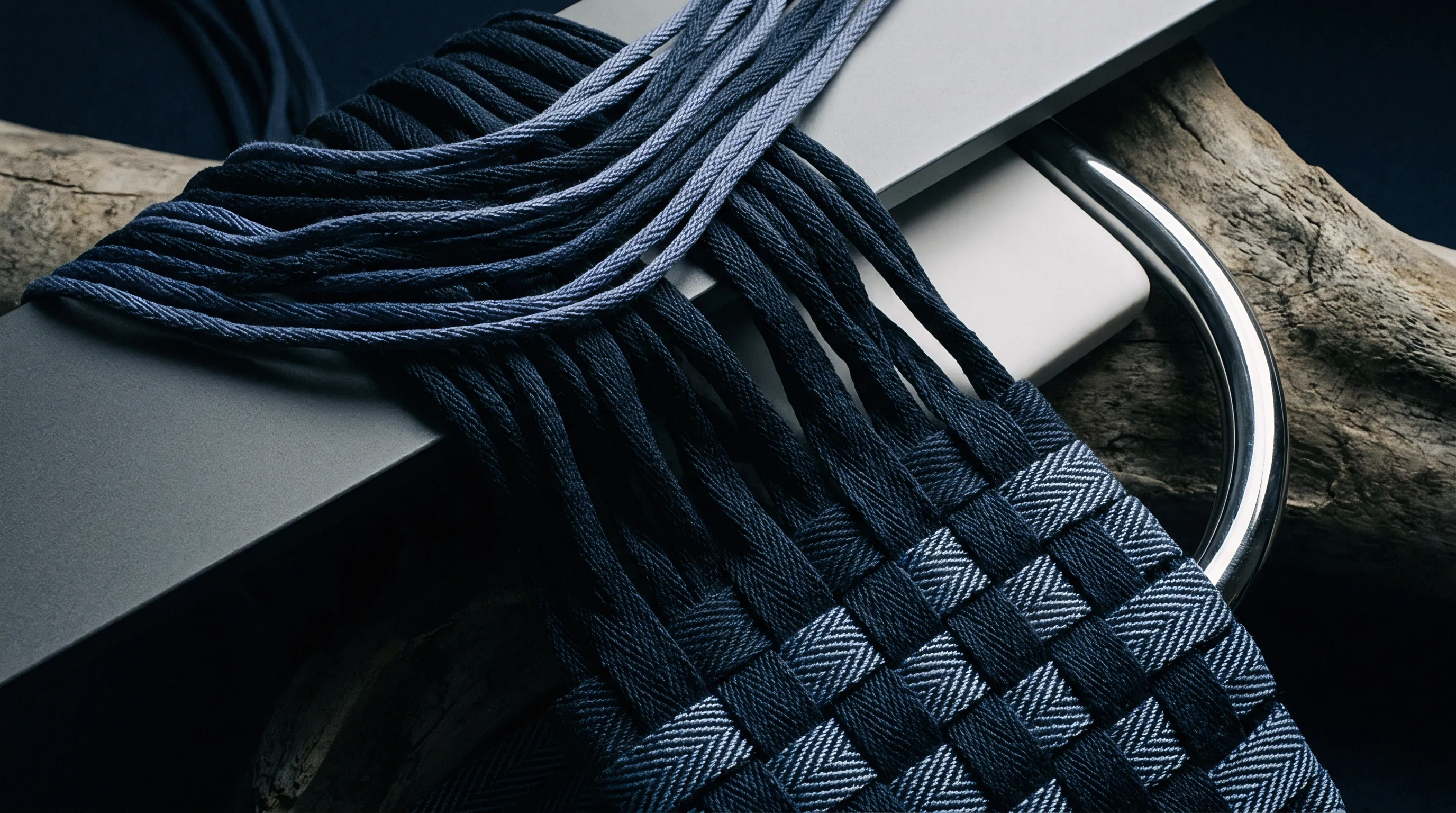
Financial losses compound quickly when fabric weight strays from buyer specs, as yarn consumption dominates overall costs. In fine-filament, high-gauge fabrics, raw synthetic yarn accounts for 55 to 70 percent of total manufacturing expenses. If warp tension drops below spec, runner lengths increase and fabric weight exceeds target tolerances.
Consider a 10,000-metre contract for E36 activewear tricot specified at 120 grams per square metre with a finished usable width of 1.60 metres. Target yarn consumption for this order is exactly 1,920 kilograms of greige fabric, plus a 5 percent process allowance, totaling 2,016 kilograms of yarn.
| Parameter | Target Spec | Loose Tension (+5% Runner) | Tight Tension (-5% Runner) |
|---|---|---|---|
| Warp Tension Target (cN/tex) | 1.80 | 1.35 | 2.25 |
| Runner Length GB1 (mm/rack) | 1680 | 1764 | 1596 |
| Finished Fabric Mass (g/m²) | 120.0 | 126.0 | 114.0 |
| Total Yarn Consumed (kg / 10,000m) | 1,920 | 2,016 | 1,824 |
| Yarn Cost Penalty ($5.50/kg) | Baseline | +$528.00 raw yarn cost | -$528.00 raw yarn cost |
| Commercial Quality Classification | First Quality | Rejected (Overweight) | Rejected (Underweight / Sheer) |
| Finished Unit Cost ($/metre) | $2.15 | $2.42 (Penalized) | $1.85 (Scrapped) |
If loose warp tension increases runner length by 5 percent, fabric weight jumps from 120 g/m² to 126 g/m². The mill consumes an extra 96 kilograms of expensive 22-dtex polyamide yarn, losing $528.00 in raw materials while producing overweight fabric. Conversely, tight warp tension yields fabric at 114 g/m², failing minimum bursting strength and opacity specs and causing complete order rejection.
Protecting spinners, knitters, and buyers requires thorough technical documentation across every processing step:
- Beam warping log entry documenting initial yarn lot numbers, creel positions, warping speed, static thread tension, and beam package density.
- Runner length certification recording on-loom physical runner measurements taken at the start, midpoint, and tail end of every knitted beam set.
- On-loom tension audit report detailing dynamic load cell baseline values, servo drive gain factors, and filter settings across all working guide bars.
- Finished fabric mass verification confirming conditioned weight per unit area, usable width, wale count, course count, and post-finishing dimensional stability.
Continuous load cell monitoring is recommended for all E36 and E40 tricot lines. Ensuring full technical auditability across the supply chain protects mills against dispute liability. When physical fabric test results match written let-off logs and calibrated runner length certificates, disputes over dimensional variance, mass drift, or shading are resolved through objective engineering facts rather than commercial arbitration.